Installation and Operation Smart-UPS® suo0648a SURT15k/20k 230 VAC Stack/Rack-Mount 6U
This manual and the safety guide are available in English on the enclosed CD and the APC Web site, www.apc.com. Uživatelská příručka a bezpečnostní pokyny jsou k dispozici v češtině na přiloženém CD a na webových stránkách APC www.apc.com. Denne vejledning og sikkerhedsvejledningen er tilgængelige på dansk på den vedlagte CD og på APC's websted, www.apc.com. Dieses Handbuch sowie die Sicherheitsrichtlinien sind in deutscher Sprache auf der beiliegenden CD und auf der Website von APC unter www.apc.
Contents Overview . . . . . . . . . . . . . . . . . . . . . . . . . . . . . . . . . . . . . . . . . . . . . . . . 1 Inventory . . . . . . . . . . . . . . . . . . . . . . . . . . . . . . . . . . . . . . . . . . . . . . . 1 Hardware . . . . . . . . . . . . . . . . . . . . . . . . . . . . . . . . . . . . . . . . . . . . . . . 1 Specifications . . . . . . . . . . . . . . . . . . . . . . . . . . . . . . . . . . . . . . . . . . . . 2 Environmental Specifications . . . . . . . . . . . . . . . . . . . . . . . . .
Troubleshooting Display Messages . . . . . . . . . . . . . . . . . . . . . . . . . 23 Maintenance . . . . . . . . . . . . . . . . . . . . . . . . . . . . . . . . . . . . . . . . . . . . 25 Replace battery modules . . . . . . . . . . . . . . . . . . . . . . . . . . . . . . . . . 25 Service . . . . . . . . . . . . . . . . . . . . . . . . . . . . . . . . . . . . . . . . . . . . . . . . . 26 Transport the unit . . . . . . . . . . . . . . . . . . . . . . . . . . . . . . . . . . . . . . .
Overview The APC® by Schneider Electric Smart-UPS® SURT15k/20k Stack/Rack-Mount 6U 230 VAC is a high performance uninterruptible power supply (UPS). It provides protection for electronic equipment from utility power blackouts, brownouts, sags, and surges; small utility fluctuations and large disturbances. The UPS also provides battery backup power until utility power returns to safe levels or the batteries are fully discharged. The UPS and the external battery pack (XLBP) are packaged separately.
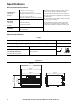
Specifications Environmental Specifications 0° to 40° C (32° to 104° F) Temperature Operating Storage -15° to 45° C (5° to 113° F) charge the UPS battery every six months 30° to 70° C (86° to 158° F) charge the UPS battery every three months Maximum Elevation Operating 3,000 m (10,000 ft) Storage 15,240 m (50,000 ft) Humidity 0 to 95% relative humidity, non-condensing This unit is intended for indoor use only. Select a location sturdy enough to handle the weight.
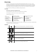
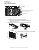
Installation Stack or rack-mount front panel PowerView Interface Display RJ45 Connector (pass through to rear panel RJ45 connector) Serial Port PowerView Cable Connector SmartSlot with Network Management Card Ethernet port 10/100 Base-T Cold Start/EPO Reset suo0643a PowerView installation for stack or rack-mount configurations Prior to attaching the PowerView to the UPS: 1. Loosen the two bracket screws on the back of the PowerView module. a.
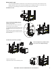
Stack configuration The UPS and the XLBPs must be connected with ground wires. Refer to the XLBP user manual for details. Always place the UPS above the XLBP(s) in a stack configuration. suo0663a Total stack configuration height is recommended NOT to exceed 18U. This is the equivalent of two XLBPs and one UPS. Four screws must be used to secure each tie bracket to the units, (see diagram).
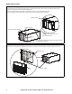
Mount units in rack The UPS and XLBP should be installed at or near the bottom of the rack. Always place the UPS above the XLBP(s). Batteries must be removed from the XLBP(s) prior to installing the unit(s) in a rack. Refer to the instructions on the packaging for details on removing the batteries from the XLBP. suo0667a Install units in rack Secure the UPS and the XLBP in the rack using the cage nuts and ornamental screws included in the package.
Route ethernet cable Ethernet cable wiring rear panel access Locate the RJ45 connector and the ethernet port on the front panel of the UPS. Connect the ethernet jumper cable (included), to the RJ45 connector and the ethernet port. Connect a network cable (not included), to the RJ45 connector on the rear panel of the UPS. There is an internal ethernet cable that connects the front and rear panel RJ45 connectors.
Install bezels suo0650a Install a bezel on the UPS and XLBP(s). Accessories Install accessories prior to connecting power to the UPS. • Refer to the APC Web site, www.apc.com for available accessories. • User documentation for the Network Management Card installed on this UPS is available on the Utility CD included with this unit.
Hardwire the UPS Wiring must be performed by a qualified electrician. Adhere to all local and national electrical codes. 1. For input wiring only, install a utility circuit breaker in accordance with local electrical codes. 2. Switch the utility circuit breaker OFF. 3. Remove the appropriate circular knockouts from the input and output wiring trays. 4. Remove the screws that secure the covers and take the covers off of the trays. 5. Remove the five screws that secure the strain relief bar. 6.
Install input and output wiring trays in UPS rear panel Input Wiring Tray RJ45 Connector XLBP Connector Output Wiring Tray Ground EPO Port Cold Start/EPO Reset suo0649a Input Wiring Tray suo0673a Ground Output Wiring Tray SURT15k/20k 230 VAC Stack/Rack-Mount 6U XLI/XLICH/XLI-CC 9
Wiring Specifications Adhere to national and local electrical codes when wiring.
Dual Feed Number of Wiring Phases Voltage Current Full Load*** (maximum) External Input Circuit Breaker Mains (typical) External Input Circuit Breaker Bypass (typical) 83 A 100 A each phase 100 A each phase Wire Wire Size Size Mains* Bypass* (typical) (typical) SURT15K XLI/XLICH/XLI-CC Input 1 220/230/240 VAC 35 mm2 35 mm2 2 25 mm2 Output 1 220/230/240 VAC 66 A not required not required 25 mm Input 3 380/400/415 VAC 28 A each phase 35 A or 40 A each phase 100 A each phase** 6 mm
Input wiring options Input wiring overview: Refer to the diagrams on the following pages for input wiring options. Main Input Power Single and Three Bypass Input Power Single and Three Main Phase 1 Bypass Phase 1 Main Phase 2 Bypass Phase 2 Main Phase 3 Bypass Phase 3 Neutral Ground GND NEU L3 L2 L1 MSJ B1 B2 B3 BSJ SJ1 Labeled jumpers must be installed in the appropriate locations.
Ensure ground wire conductor and insulator are securely fastened. To connect the ground wire: 1. Strip the cable of insulation, exposing the wire. Secure the exposed wire with lug “A”. 2. Secure the insulated portion of the cable with lug “B”.
Input wiring option 3 Three phase input, single phase output, single feed GND NEU L3 L2 L1 B1 B2 Input wiring option 4 Three phase input, single phase output, dual feed B3 GND NEU L3 L2 L1 B1 B2 BSJ B3 BSJ Input wiring option 5 Three phase input, three phase output, single feed GND NEU L3 L2 L1 B1 B2 suo0679a suo0678a SJ1 Input wiring option 6 Three phase input, three phase output, dual feed B3 GND NEU L3 L2 L1 B1 B2 B3 SJ1 SJ2 14 SURT15k/20k 230 VAC Stack/Rack-Mount 6U XLI/XLICH/
Output wiring options Output wiring overview. Refer to the diagrams on the following pages for output wiring options. Labeled jumpers and connectors must be installed in the appropriate locations. Output Phase 3 Output Phase 2 Neutral Output Phase 1 Ground N Factory Default Configuration L3 L2 L1 Output Shorting Jumper (OSJ) for single phase output OSJ suo0682a PDU Terminals L3 L2 L1 OSJ Ensure the OSJ is secured to the output wiring tray using the five screws provided.
Output PDU option Single phase output connection to battery pack PDU N L3 L2 L1 OSJ Ensure the OSJ is secured to the output wiring tray using the five screws provided.
Operation The UPS has three operation mode options. Normal operation During normal operation, the UPS double converts utility power to conditioned power for the connected load. Battery operation During battery operation, the UPS provides power to the connected load from batteries for a finite period of time. The UPS transfers to battery operation if the supply of utility power fails or is outside predefined limits. Bypass operation Bypass mode is reached either as a user selection or automatically.
Navigating menu screens Use the ESC key to navigate between menu screens. Use the UP/DOWN arrow keys to scroll through the list of sub menus and commands on any screen. arrow indicates that there are sub menus containing user selectable commands. to navigate to a sub menu and to select user configurable commands. To access the overview status screen on the LCD press the ESC key. To access the main menu screen from the overview status screen, press the ENTER key.
Sub menu screens Logging Display Diags Help Control Status Setup Batteries Logging Display Diags Help Control Status Setup Batteries UPS into Bypass Do Self Test Simulate Power Fail Start Runtime Cal Vin Vbyp Vout 1 2 3 Iin Turn Load Off Ibyp Iout su0199a 1 2 3 kW kVA 1 2 3 Load Bat Voltage Bat Charge Runtime Alarms Clock Other Bat AmpHr UPS Temp Low Batt Dur Shutdown Dly Turn On Dly Return Bat Cap Default Alarm Thresholds Load Runtime Set all UPS settings to Factory Defaults NO, ABORT
The PowerView will reference XLBP configuration in the following manner.
Start-Up Connect load to UPS 1. The UPS features chassis ground connection screws located on the rear panel, for connecting the ground leads on transient voltage devices. Prior to connecting the grounding cable, ensure that the UPS is NOT connected to utility or battery power. 2. Connect equipment to the UPS. NOTE: This UPS is equipped with an external battery connector on the rear panel of the unit. 3. The battery charges to 90% capacity during the first three hours of normal operation.
Emergency Power Off (EPO) The output power can be disabled in an emergency by closing a switch connected to the EPO. Adhere to national and local electrical codes when wiring. The switch should be connected in a normally open switch contact. External voltage is not required; the switch is driven by 12 V internal supply. In closed condition, 2 mA of current are drawn. The EPO switch is internally powered by the UPS for use with non-powered switch circuit breakers.
Troubleshooting Display Messages Use the table below to solve minor installation and operation problems. Refer to the APC Web site, www.apc.com for assistance with complex UPS problems.The PowerView reports various messages on the display, including alarm status and changes in system configuration. This section lists all the PowerView display messages, the reason for the message, and the appropriate corrective action. Messages may occur simultaneously.
Condition Threshold Alarm PowerView Display Message Load Power Is Above Alarm Limit. Reason for Message The load has exceeded the user- specified load alarm threshold. Corrective Action Option 1) Use the display interface to raise the alarm threshold. Option 2) Reduce the load Load Is No Longer Above Alarm Threshold. The load exceeded the alarm threshold. The situation has been corrected. Either because the load decreased or the threshold was increased. Min Runtime Restored.
Condition General Fault PowerView Display Message Reason for Message Fan Fault A fan has failed. Static Bypass Switch Fault. The static bypass switch has failed. System Failure Detected by Surveillance. The system has detected an internal error. System Not Synchronized to Bypass. System cannot synchronize to bypass mode.Bypass mode may be unavailable. Corrective Action Contact APC Customer Support. Refer to Contact Information in this manual. Check for other alarms.
Service If the unit requires service, do not return it to the dealer. Follow these steps: 1. Review the Troubleshooting section of the manual to eliminate common problems. 2. If the problem persists, contact APC Customer Support through the APC Web site, www.apc.com. a. Note the model number and serial number and the date of purchase. The model and serial numbers are located on the rear panel of the unit and are available through the LCD display on select models. b.
Two-Year Warranty The limited warranty provided by American Power Conversion (APC®) in this statement of Limited Factory Warranty applies only to products you purchase for your commercial or industrial use in the ordinary course of your business. Terms of warranty APC warrants its products to be free from defects in materials and workmanship for a period of two years from the date of purchase.