
Specifications

990-2870 01/2006
*990-1747C*
®
Smart-UPS
®
VT ISX
Installation
Important Safety Instructions –
SAVE THESE INSTRUCTIONS
Note
Always read the separate Safety sheet (990-2822) prior to the
installation.
Warnin
g
Always carry out the Total Power Off procedure prior to the
installation. Refer to the Safety sheet (990-2822) for details.
Warnin
g
All electrical power and power control wiring must be installed
by a qualified electrician, and must comply with local and
national regulations for maximum power rating.
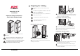
1
Preparing for Cabling
Preparing for cabling (general)
Pull out the lower end of the handle and turn the handle
counterclockwise to a horizontal position to open the door.
Using a torx screwdriver, loosen the 12 M4 screws from the cable
landing covers and remove.
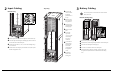
Note
Make sure the UPS is in its location of use before wiring
begins.
Warnin
g
The UPS must be supplied from a: 480Y/277V 4W + GND
or 480V 3W + GND 60Hz source.
Caution
Verify clockwise phase-rotation (L1, L2, L3) and make sure a
neutral connection is present.
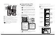
Caution
The installation must comply with all national codes.
Note
Power terminal lug diameter: minimum 6 mm.
Torque value: 45 lbf
.
in/5 Nm.
Smart-UPS® VT ISX w/transformer, 20-30 kVA, 480 V, Installation
Cut crosses for cable access in the required number of the 6 blanking
plugs (use top blanking plugs for top entry, bottom blanking plugs for
bottom entry). Line hole(s) with grommets.
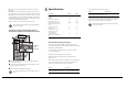
Preparing for bottom entry cabling
Remove the 2 M4 screws from the bottom plate and remove plate.
Punch holes in the labeled area of the bottom plate for conduits as
required. Line hole(s) with grommets.
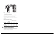
Preparing for top entry cabling
From the rear of the inside of the UPS push the two top cover spring
locks backwards to lift up rear end of top plate.
Slide out the top plate (mind the wing on either side of the plate).
Punch holes in the top plate for conduits in labeled area as required.
Line hole(s) with grommets.
Rear
Rear