ULTIMATE REVERSE OSMOSIS SYSTEM INSTALLATION INSTRUCTION & OWNER’S MANUAL Ver 1.0 Models: Mode els: R RO-QUICK90 O-QUICK90 www.FreeDrinkingWater.com www.FreeD Drin nkingWater.
Please keep this Owner’s Owner’s Manual for future e reference. reference. It contains useful information on how to maintain and care for your APEC Reverse Osmosis water filter system. TABLE OF CON CONTENT NTE TENT NT 1. In Installation: 2. Maintena Maintenance: anc nce: e: 3. Owner’s Manual - RO Basics: 4.. 4 Trouble-shoot Guide: T 5. Other Information: 6. W Warranty ..................... ....................................................................................... ........... ........
Thank T hank you for choosing A APEC PEC reverse osmosis system systems. ms. You now own the ffinest inestt water filter in America.. Ple se read and become familiarr with Please Plea with instructions insstructions and parts needed before befor ore e proceeding pro pr oceeding with the iinstallation. nstallation. BEFORE INSTALLATION: Inspect the system: Please take the system and all the components out of the box. box ox.
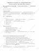
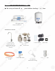
Components Com mponents included with the RO O system: system: Make M ake sure you have all these these parts before starting installation. in nstallation.
Component Com mponent Itemization: 1) Sediment pre-filter (1st-stage ge fil filter) ilte t r) 2) Carbon pre-filter ( 2nd-s -stage -sta tage ge ffilter) ilter) 3) Membrane and hou housing ousi sing ng (3rd-stage filter) 4) Carbon post post-filter t-ffil ilte t r (4tthh-stage filter) 5) Storage ta tank ank 6) valve Tank ball val T alve ve 7) ASO – Automatic Shut Off valve 8) Check valve (Internal check valve encased in plastic fitting) 9) T-fitting 10) Feed water inlet 11) 11) Product (f
INSTALLING INST STAL ALLI LIN NG THE SYSTEM Space: Make sure there is sufficient sspace installation pace under the counter for installat pa tio ion n (a (an n area of about H for for the the system, 11”D x 18”H for tank). 14”L x 6”W x 6.5”H The RO system is bestt installed installed t under the kitchen sink.
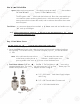
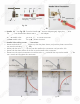
Fig.. 2 - N eedle Valve Installation. Needle Attach the needle valve (C) to water wat ater er supply supply adapter (A). Please apply appl plyy 5-6 5-6 wraps wr of teflon tape to needle valvee prior pr to connecting it to the water supply supp ply adapter ada dap pter (A). Fig. 3 - If your pipe has a 1/2”” Co Conn nnec e tion. Connection. By attaching the 1/2” x 3/8” 3//8” converter (B) to the Male end of the water supply adapter (A), you now have a 1/2” Male and Female water supply adapter. Fig.
3. Recomm men end d Connection Connection For Flex Line Riser: See See Fig. Fig Fi g. 5A. & Fig. 5E Loosen nut and d separate sepa se para rate cold Recommend water riser rise ri serr tube tube from shut off valve. Gently bend ben nd riser rise ri serr tube so that the Feed Water Adapter Adap apte terr (Fig. 1) fits to the the shut off valve. Connect the riser tube, tub be, feed feed water adapter, and shut off valve va together to onto and ti igh ghte ten. tighten. For Solid Copper Riser: See Fig. 5 B.
Insert Sleeve Slee eve Compre Compression pressi ssio on Nut Push the tubing all the th he way into the needle needle valve while tightening compression com mpression nut. Apply l T Teflon fl T Tape Here H Fig. 5C Fi Fig g. 5D Fig. 4. Needle Valve: Val alve ve: See Fig. 5D. Screw the Needle V alvve onto the Adaptor tightly. Apply 6-8 al 8 rrounds ound ou nds of Valve Teflon n tape tap apee onto Needle Valve before attaching attachi hing ng itit to the Adaptor.
Test for leaks lea eaks ks after after the system y is completely p y installed: installle led: d: Close Clo lose the Needle Valve (turn ( needle need dle handle han andl d e clockwise all all the the wayy in to close). ) Turn ON the cold d water wate wa terr supply pp y to the sink faucet. If the Needle Need Ne edlle Valve or the Adaptor Ad dap apto ptorr leaks,, check the connection and tryy applying ap pp y g more Teflon tape p or tighten g e thee brass brass nut some more m mo re to stop p the leak.
3. See Fig. 8, 8A. 8A. Make sure to align g the drain n saddle sad addl dle hole to the drilled hole perfectly. per p rfe fect ctly ly. y. Mis-aligning Mis-alilign gnin ing these two holes will block the drain dra ain water wat ater and cause membrane damage. damage ge.. Attach Attta tach ch the the h drain saddle to the drain pipe and and tighten titig ghten the two screws evenly.
3. For Porce Porcelain cela lain in Sink: Porcelain enameled sinks can ca an readily read re adily be chipped if care is not exercised exerrci cise sed d when w en wh drilling g the the hole. Before starting the drill motor, motor or,, apply appl ap plyy firm downward pressure on thee bit bit until until a crunching cr run u ch chin ing occurs. This will help keep the drill d illl bit dr bit from walking when starting the hole.. A small pilot holee will ho will also aid the drill bit.
Faucet stem Sleeve & Tube insert Compression nut Counter Top Faucet cet Ba Bas Base se Fig.9D Counte Counter er Top Top Openin Ope ning g Opening Tube insert Black Loca Locating ating Washer Lock Washer Lock Nut Sleeve Insert Sleeve Compression nut Compression Compression Nut N Tubing Fig. 9B Fig.9C Step 5: Positioning The System system 1. Main System: The main system can stand in the sink cabinet. No need to mount the syste em to the the wall.
Step 6: Connecting Conn Co nne ecting The System IMPORTANT IM MPORTANT INSTALLATION NOTICE! NOTICE! The Quick The Quick connect fittings come with an an eend en d plug that needs to be removed before bef efor oree the tubing can be connected. Please disconnect the end plugs at Points A, G and H from the Quick connect fittings before connecting tubing. See Fig.10A and Fig.10B. A G H Fig.10B F g. Fi g.10 10A A Fig.
To Disconn Disconnect nnec ect the Tubing: g Fig.10B. See Fi Fig.10 1 B. Push in and hold down on the collet col olle lett ring r ng square ri against agai ag ains nstt the the fitting. With the collet held in this thi hiss position po osition the tube can be removed. removed. See Fig.10E. Summary of Tubing Connections: Fig.10E There are 4 connections: See Fig. 11 & Fig. 11A. Point A to X: Connect Co Conn nnect RO to COLD water supply — Red Red tubing. tubing.
Option O ption 1 Diagram DRINKING WATER A FAUCET Z SINK TTO ICEMAKER OPTION INPUT WATER INPUT A W DRINKING DR DRINKI NKING NG WATER WATE WA ATE TER DRAIN DRA IN WATER A Y H 1st Stage 4th Stage 2nd Stage 3rd Stage A G DRAIN LINE 1st SStage t ag age e - Sediment prer t age - Carbon prer 2ndd SStage 3 rd Stage - Membrance and housing 4 th Stage - Carbon post-filter Fig.
3. Point W - D Drain rain water connection: ra Tubing Tu Tubi bing ng color: color: Black tubing. Connect the BLACK BLLAC ACK K tubing from the RO to the Drain Draiin Saddle. Sadd ddle le. Fitting Fi ittttin i g type: Simply push the Clear tubing g into int nto the Quick Connect fitting. No No Inserts, Inse In sert rts, Sleeves or Nuts re the the connection. con onnection. No Teflon T here he re.. are needed to secure tape needed here. 4 Point A - System water inlet (to Stage 4.
Option: p Mouting Mout Mo utin ing The RO System You can Y can a mount mount the RO system on a side of cabinet cabi b ne nett or wall. See Fig.13A. This RO system sy m is is also designed to sit neatly neat ne atly ly in the sink cabinet without mounting. See See Fig.13B. This makes future filter fililte terr change cha ch ange easy and conv co nven e ient. If you prefer to mount the system sys yste tem m to o the wall, please make sure it can n be be taken takken down easily for ta convenient.
Option: p Ice-maker Icce-m -ma aker Connection If you u want wan antt to connect product water from the RO to to your ice-maker, you will need: x One T-fitting, preferably the quick-connect quic qu ickk-cconn n ect type fitting x One x Extra 1/4" tubing long enough enoug gh to go go from the RO system to your ice-maker ice-makker x Extra x One x One shut-off valve, preferably the the quick-connect type. type. See Fig.13.
Step 7: Sys yste tem m Start-Up System 1. T Tur urn on feed water: Slowly, turn on your Cold Col old d water supply. Open the Needle Valve V lvee (turn Va (t Turn countercloc cl ckw k ise) to allow the raw water to enter the the system. Check for leaks! clockwise) 2. O 2 pen tank valve: Open the tank’s tankk ’s ball bal alll valve v lve to allow water to enter the tank. va tankk.
SYSTEM M MAINTENANCE MAI AINT N ENANCE The Th he system syst sy steem requires very little maintenance. maintenanc nce. e. Just Jusst change the filter cartridges regularly regul ular arly ly as as suggested below. Keep Ke ep the the system indoors away from extreme exxtr trem emee heat he or cold temperatures, and run the the system sys ysttem within its reasonable output capacity (i.e. allow the re the system sys ysttem to rest at least a few hours a day).
FILTER CHANG CHANGE GE IN INST INSTRUCTIONS STRUCTIONS How w To Replace Replace Stages 1, 2 Pre-Filters: Turn n OFF OFF cold water supply to RO system. m. Turn rn OFF OFF tank’s ball-valve. Turn ON N the the RO faucet faucet briefly to reli re liev evee the built-up pressure inside thee RO RO system. sysstem. This will make opening the housings sy hou ousi sing ngss easier. relieve **Please Please remove red locking clips from St Stage 1 & 2 tubing connection parts before replacing Stage 1 & 2 filters.
Add a little bit llubricant ubricantt o ub on n double o-rings. Turn counter-clo counter-clockwise ock ckwi wise se to o open the membrane membr bran ane e housing cap. Fig. 14B Fig. 14A Fi How to Replace Stage-3 Membrane: OFF the cold 1) Turn T cold water water supply to RO system. Turn OFF OFF tank tan ank ball-valve. Lift up RO faucet leverr briefly brie br ieflfly to relief the built-up bui uiltlt-u -up p pressure inside the RO system. This Thi hiss will will make opening the housings easier.
OWNER’S MANUAL Please read tthis his ssection ection for useful RO system ma and nd maintenance ma aintenance information. TABLE OF CONTENT Part I: RO O Basics B sics Ba Basic Basi Ba sic terms ............................................. ................................................................................. .... . ................................... page 23 System flow diagram ...................... ................................................................... ...... . ................
Part I:: RO RO BASICS This section provides basic concepts This ts on on how h w an RO system works, how it performs ho perrfo form rmss in relation to your house’s water condition. We hopee th ho this is iinformation nformation helps keep your RO system nf m rrunning unning at top un performance for years to come.
3) Water Pressure Pres Pr essu sure r – The Most Important Factor! RO sys systems ystems ms run on water pressure. Therefore your your water water pressure has the most direct direc ect effect effeect on how well your you ur RO will perform. With sufficient water er pressure pressure (85 psi max.), your RO system sys yste tem m will wiill function well, give gi ve high high output with high removal rate, ratte, and and fill filll up the storage tank quickly.
6) How Full ll Can Can My Tank Fill Up? Your water wat ater er pr p pressure essure and temperature will determine deteerm rmiine how full and how fast the storage tank tankk will be filled up. The The stronger s ronger your input water pressure, thee faster st fast fa ster and fuller the tank can fill. If If water wate wa ter pressure is low, the tank ta nk will will fill slower and will not fill up to to its its full fu capacity. capacity.
10) Insufficient Insuffici cien entt Water W ter Pressure – Problems with Non-Pump Wa Non on-P -Pum u p RO Systems: The 3 most most common problems caused by low input inp nput ut water pressure: T geet little lilittttle le water watter from tank 1) Tank does not fill up, get dispe pens nsin ing g faucet 2) Sluggish flow at the dispensing th han the the claimed GPD 3) RO makes water slower than If you experience these problems, Please check your input water pressure as the first step.
Part II: Trouble-Shoot Troub ble-S Shoot Guide For Newly y Installed Installed RO System y Affte After terr installation, inst in stal a lation, if you encounter any off the th problems prob pr obllems described below, please follow fol ollo low w this th guide to troubleshoo sh oot. t. In most cases, the problem is quickly qui uick ckly ly solved sollved by following this guide. shoot. N on-Pump RO HEAD DIAGRAM Non-Pump Stage 3 Stage 2 Stage 1 Stage 4 Fig.
1) Air Bubb Bubbles: bble les: s: Lots of Air bubbles in cup p or bottle bot ottl tle e when filling g It is is quite quititee normal to see air bubbles in a cup qu up of of pure water. This mainly occurs when when a RO unit is first installed instal in alled or when filters are being replaced. repl p aced d. When Wh new filters are installed to the the unit, uniti, the un the filter housings aree dry. When they are attached onto ar on nto the the RO RO head, air pockets will fill the housing.
3) Sluggish gg sh Flow F lo low w At Dispensing p g Faucet - Insufficient Insu s ff ffic icie ient water pressure (see “RO Basics” for fo or explanation) explanation) —> Check water pressure. pressur ure. e. If If too low for this chos ch chosen sen e RO model, either increase your water wa ate terr pressure p essure or add pump to RO system. pr sys yste tem. m. - Input water to RO is blocked —> Make Mak akee sure sure Feed water valve is fully opened and and unhindered.
6) TDS (Total (T (Tottal Dissolved Dis issolved Solids)) Level Reads Higher Highe g er Than Than Normal Ho ow to test TDS correctly: y How See “TDS M Meter eter et er -- How to Test Your Water Quality Quality” y ” in instructions nst strructions on page 25. If the filtered water’s TDS reads higher hig ighe herr th than the normal 10% range, these are tthe he possible causes: - Forgot to insert membrane into its housing —> Put membrane into housing.
7) There is a leak lea eak at the Tank ball valve connection conne nect ctio ion n If you you are are experiencing a leak from where thee tank ta ball valve attaches to the tank stem, m, you may not stem have ha ve applied enough Teflon tape to the ste em when h you first installed the valve. valve ve. To correct cor o rect this issue, ple pl ease turn off the supply water to the the system syst sy stem m and turn on the drinking water faucet fauc fa ucet et to to completely empty please tthe he tank.
10) How to Test 10)How Tes estt RO’s RO Shut-Off Function: Th The he RO system should shut off automaticallyy when wh the tank is filled. When the RO fails faiils to to shut off after tankk is ta is filled, drain water will keep running down dow the drain depleting the pre-filters, pre-f -fililte ters rs,, the t e membrane, and th may lead to higher water bills. To test ma tes estt if your you ourr RO system is shutting down normally, norrma malllly, y, please please follow the steps below.
12) RO Makes Mak akes es Humming Humming g Noise Wh n RO When RO makes a humming noise, most likely like kely ly it’s caused by air bubbles being g trapped trappe ped d in the “Check Valve” Fig. Valv Va ve” e during installation. See check valve on F ig. 17, point E (Page 27). TTo o purge air from the check valve, do do as follows: follows: Step 1: Close the tank’s valve. Step 2: Tilt the RO system to the right. Put something under the 3rd filter housing to keep RO tilted.
OTHER IN INFORMATION NFORMATION AirGap Faucet Fauce cett Installation Inst In stal allation (Optional) Therre are There are 3 colored tubings on your Air-Gap faucet. fau fa ucet. At the end of each 1/4” tubing tubi bing ng there the here is a “Quick Connect ne ct”” fitting. fi fitting gs is used use sed d to connect the Pure and Drain water wate wa terr line lilin ne from the RO unit to nect” The Quick Connect fittings the Air th Air Gap Faucet.
LIMITED PRODUCT WARRANTY Scope Scop Sc ope pe APEC A PEC takes pride in selling a superb line of products, pro rodu duct cts, s, including inc ncluding this reverse osmosis system (“Product”). As As such, APEC expressly warrants to the original purchaser that, for a period per erio iod d of one (1) year from the date of purchase, the Product will be reasonably free of defects in materials and workmanship.
CONDITIONS CONDIT ITIO ION NS THAT RENDER THIS LIMITED PRODUC PRODUCT UCT T WA WARRANTY VOID THIS TH HIS LIM LIMITED IMITED PRODUCT WARRANTY SHALL BE VOID IF: 1.. The Product is not operated in compliance municipal water conditions for which the particular 1 ce with witith h normal no part pa rtic icul ula ar model of this Product is intended. 2. The person seeking to invoke the warranty is not the original purchaser. r That is, this Limited Product Warranty only extends to original purchasers. 3.
Advanced Advanc ced Purification Engineering Corp. Corrp. 1320 S Johnson Drive City of Industry, CA 91745 For questions o orr ccomments omments please visit our web website bsite a at: t: www.FreeDrinkingWater.com ww ww.FreeDrinkingWatter.co om For technical support contact us at: Techsupport@freedrinkingwater.