
Instructions / Assembly

20
FILTER CHANGE INSTRUCTIONS
How To Replace Stages 1, 2 Pre-Filters:
Turn OFF cold water supply to RO system. Turn OFF tank’s ball-valve. Turn ON the RO faucet briefly to
relieve the built-up pressure inside the RO system. This will make opening the housings easier.
*Please remove red locking clips from Stage 1 & 2 tubing connection parts before replacing Stage 1 & 2
filters.
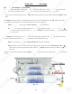
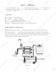
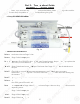
The Stage-1 Sediment filter is tucked between stage 2 & 4 CT-24CAB filters (see Fig. 14). For ease of ac-
cess, please tilt the filters to a convenient position then do the following:
Step 1. Disconnect tubing from Point A & Point I, discard used filter.
Step 2. Snap on the new filter onto the 2 holding clips. Make sure the Flow direction “arrow ”
on the filter is pointing toward the output direction Point I. Re-connect tubing securely to both ends
of the new filter.
The Stage-2 Pre-Carbon filter is located above the 3rd stage membrane filter (See Fig. 14). For ease of
access, please tilt the filters to a convenient position then do the following:
Step 1. Disconnect tubing from Point B & Point K. Discard used Filter.
Step 2. Snap on the new filter onto the 2 holding clips. Make sure the Flow direction “arrow ”
on the filter is pointing towards the output direction Point B. Reconnect tubing to both ends of the
new filter.
*Please re-install red locking clips from Stage 1 & 2 tubing connection parts after tubings are connected to
the filters.
Fig. 14
Stage 1
Stage 2
Stage 3
Stage 4
20
FILTER
C
HA
NG
G
E
E
ININ
ST
ST
R
UC
TI
O
N
S
Ho
w
w
To
To
R
R
e
ep
lace Stages 1, 2 Pre-Filters:
Tu
rn
n
O
O
FF
FF
cold water supply to RO syste
m.
m.
Tu
rn
rn
O
O
FF tank’s ball-valve. Turn O
N
N
thth
e
e
RO
RO
f
f
aucet brie
f
ly to
rere
li
li
evev
e
e
the built-up pressure inside t
he
e
RR
OO
sy
sy
s
st
em. This will make opening the h
ou
ou
sisi
ngng
s s
easier.
*
*P
lease remove red locki
ng
cli
ps
f
rom
St
St
ag
e 1 &
2
tubin
g
connection
p
arts be
f
ore re
pl
acin
g
St
ag
e 1 &
2
fi
lt
er
s.
Th
e
Stage-
1
Sediment
f
ilter is tucked between stage 2 & 4 CT-24CAB
f
ilters (see F
i
g. 14
)
. For ease o
f
a
c-
c-
c
ess, please tilt the
f
ilters to a convenient position then do t
he
e
f
f
ol
o
lowing
:
Step 1.
Di
i
scsc
onon
ne
n
ct tubing
f
rom
Po
in
t
A
&
Po
in
t
t
I
I
,
,
didi
sc
sc
ard used
f
ilter.
St
ep
p
2
2
.
.
SS
na
p on the new
f
ilter onto the 2 h
ol
ol
didi
n
ng
clips. Make sure the
Flow directi
on
on
““
ar
ar
row ”
on
on
t
t
he
he
f
ilter is pointing toward the out
pu
pu
t
t
di
di
re
re
ct
ion P
oi
nt
I
. Re-connect tubing
se
e
cu
cu
re
re
ly
ly
to both ends
ofof
t
t
h
he
new filter
.
r
r
ThTh
e
e
Stage-
2
Pre-Carbon
f
ilter is lo
ca
a
tete
dd
above the 3rd stage membrane
f
ilte
r
r
(S(S
eeee
F
Fi
g. 14). For ease
of
access, please tilt the
f
ilters to a c
on
n
ve
ve
ni
ni
ent position then do the
f
ollowing
:
Step 1.
D
isconnect
tt
ubub
inin
gg
f
rom P
oi
n
t
B & P
oi
n
t
K. Discard used Filte
r.
Step 2. Snap on the new
f
ilter onto the 2 holding clips. Make sure the
Flow direction “arro
w
w
”
on the
f
ilter is pointing towards the output directi
on
n
P
P
oi
o
nt
B
. Reconnect tubing to both e
nd
d
s
ofof
t
t
h
he
new filter
.
r
r
*Please re-install red locking clips
f
rom Stage 1
&
&
2
2
t
t
ub
ub
ing connection parts a
f
ter tubin
gs
s
aa
re
re
connected to
th
e
f
i
lt
t
erer
s.
s.
F
i
g.
14
Stage
1
Sta
Sta
g
ge
2
Sta
Sta
ge
g
3
Stage
4