ULTIMATE PERMEATE-PUMPED REVERSE OSMOSIS SYSTEM INSTALLATION INSTRUCTION & OWNER’S MANUAL Ver 3.
Please keep this Owner’s Manual for future reference. It contains useful information on how to maintain and care for your APEC Reverse Osmosis water filter system. TABLE OF CONTENT 1. Installation: 2. Maintenance: 3. Owner’s Manual - RO Basics: 4. Trouble-shoot Guide: T 5. Other Information: 6. W Warranty ........................................................................... page 38 Preparation ................................................................... Filter housings assembly ....
Thank you for choosing APEC reverse osmosis systems. You now own the finest water filter in America. Please read and become familiar with instructions and parts needed before proceeding with the installation. BEFORE INSTALLATION: Inspect the system: Please take the system and all the components out of the box. Inspect the system and all the connection fittings carefully, make sure nothing is damaged during shipping.
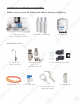
Components p included with the RO system: y Make sure you have all these parts before starting installation.
Component p Itemization: 1) Bracket 2) Membrane and housing (4th-stage filter) 3) In-line carbon filter (5th-stage filter) 4) Sediment pre-filter and housing (1st-stage filter) 5) Carbon block pre-filter and housing (2nd-stage filter) 6) Carbon block pre-filter and housing (3rd-stage filter) 7) Storage tank 8) Tank ball valve 9) Permeate pump 10) Check valve (internal check valve encased in plastic fitting) 11) T-fitting 12) Feed water inlet 13) Product (filtered) water outlet 3
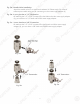
Fitting Types: There are 2 types yp of fittings g provided p for connecting g the system y 1. Quick-Connect (QC) fitting: (no insert, sleeve, or nut) Most of the fittings on the RO unit are this type. Fig. 1A Fig. 1 How to Connect: - See Fig.1. Push the tubing into the Quick-Connect fitting, then gently pull back on the tubing to make sure connection was secure. - No inserts, sleeve, or nuts are needed to secure the connection. - No Teflon tape! To Disconnect: - See Fig.1A.
THERE ARE TWO PARTS TO INSTALLING THE RO SYSTEM: Part I. Part II. Assemble the filters and housings onto the main system Installing the system Note: The RO Membrane Element has already been pre installed. PART I. ASSEMBLE THE FILTERS AND HOUSINGS ONTO THE MAIN SYSTEM Remove plastic/paper wrappings on the 3 filters, put them into the 3 housings, and assemble the housings onto the main system as follow: 1. See Fig. 2 Stand the 3 housings upright. Make sure each housing has a rubber O-ring in its groove.
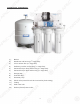
PART II. INSTALLING THE SYSTEM Space: Make sure there is sufficient space under the counter for installation (an area of about 12”L x 6”W x 18”H for the system, 11”D x 18”H for tank). The RO system is best installed under the kitchen sink. But if that is not feasible you can install the system anywhere where there is a cold water supply with sufficient water pressure for RO-PERM, and an outlet to drain off the waste water from the system. Mounting: No need to mount the system on the wall.
Fig. 5A - Needle Valve Installation. Attach the needle valve (C) to water supply adapter (A). Please apply 5-6 wraps of teflon tape to needle valve prior to connecting it to the water supply adapter (A). Fig. 5B - If your pipe has a 1/2” Connection. By attaching the 1/2” x 3/8” converter (B) to the Male end of the water supply adapter (A), you now have a 1/2” Male and Female water supply adapter. Fig. 5C - If your pipe has a 3/8” Connection.
3. Recommend Connection For Flex Line Riser: See Fig. 6A. & Fig. 6D. Loosen nut and separate cold water riser tube from faucet shank. Gently bend riser tube so that the Feed Water Adapter (Fig 5) fits onto the faucet shank. Connect the riser tube, the feed water adapter, and faucet shank together and tighten. For Solid Copper Riser: See Fig. 6B. Follow the same procedure as for flex line. If the copper riser cannot bend, then it’s best to replace it with a flex line riser.
Fig. 6C Fig. 6D Fig. 6E 4. Needle Valve: See Fig. 6C. Screw the Needle Valve onto the Adaptor tightly. Apply 6-8 rounds of Teflon T tape onto Needle Valve before attaching it to the Adaptor. To open needle valve: To close needle valve: Turn T needle handle counter-clockwise. Turn T needle handle clockwise. Test for leaks at this point: p Close the Needle Valve (turn needle handle clockwise all the way in to close) Turn ON the cold water supply to the sink faucet.
Step 2: Drain Saddle Installation Note: To avoid annoying y g drainage g noise,, mount drain line as low as possible p on the vertical tailpiece, p , or on horizontal tailpiece. p There is constant water pressure “packed” inside the RO system which blocks the waste water from backing-up into the system. So the waste water is “forced-drained”, not “gravity-drained”. 1. See Fig.7. The drain saddle assembly should be installed above the trap and on the vertical or horizontal tailpiece.
3. See Fig.9, 9A. Make sure to align g the drain saddle hole to the drilled hole perfectly. perfectly p y y. Mis-aligning these two holes will block the drain water and cause membrane damage. Attach the drain saddle to the drain pipe and tighten the two screws evenly. 4. Once the drain saddle is secured, push 1/4” black drain tubing into the Quick Connect fitting on the saddle. DO NOT use a “Insert” on the drain tubing. Fig.
3. For Porcelain Sink: Porcelain enameled sinks can readily be chipped if care is not exercised when drilling the hole. Before starting the drill motor, apply firm downward pressure on the bit until a crunching occurs. This will help keep the drill bit from walking when starting the hole. A small pilot hole will also aid the drill bit. Note: Immediately after the hole drilling is done, clean up all metal chips, as metal chips will stain the porcelain!! Step 4: Mounting The Faucet 1.
Step 6: Connecting The System Summary of Tubing Connections: There are 4 connections: See Fig 11 and 11A Point A to X: Connect RO to COLD water supply — Red tubing. Point G to Y: Connect product water from 5th-stage filter to tank — Yellow w tubing. This tubing is a 2-way line, Product water enters and leaves the tank via this line. Point H to Z: Connect product water from 5th-stage output to dispensing faucet — Clearr tubing.
Drinking Water Faucet Fig. 11A Fig Details on Tubing Connections: Please: Do not disconnect the 4 lines on the Pump! p No need to touch these lines for installation. Switching the lines on pump will cause Pump to malfunction. To ensure a smooth and correct installation, please connect the water lines following the sequence and orderr outlined below. Refer to Fig.11 & 11A A for proper point locations. 1. Point Z Faucet connection: Tubing color: Fitting type: Clear tubing.
3. Point W Waste water connection: W Tubing color: Fitting type: Black tubing. Connect the BLACK tubing from the RO to the Drain Saddle. Quick-Connect fitting on drain saddle. No teflon tape. Do Not add ”insert” into Black tubing. Simply push tubing into port. 4. Point A System water inlet (to Stage 1 prefilter) connection: Tubing color: Fitting type: Red tubing. Connect the RED tubing from the Feed Water Valve to the RO’s stage -1 prefilter. Quick Connect fitting See Fig.1 on page 4.
Standard 4-gallon Tank Diagram: Tank Ball Valve Fig. 12 OFF Position ON Position How The Permeate Pump Works: The permeate pump has a built-in Auto-Shut-Off (ASO) feature that functions like the ASO valve on a non-pumped system, so you don’t need a separate ASO valve on the system. The pump operates by collecting the RO’s waste water, and storing it up in the pump chamber for a few seconds (interval depends on water pressure) until sufficient pressure is built up.
Option: p Ice-maker Connection If you want to connect product water from the RO to your ice-maker, you will need: x One T-fitting, preferably the quick-connect type fitting x Extra ¼ “ tubing long enough to go from the RO system to your ice-maker x Optional: One shut-off valve, preferably the quick-connect type. See Fig.13. Before connecting the product water line from Point Z to H, add a T-fitting near point H to divert product water to both the ice-maker and the faucet.
Step 7: System Start-Up 1. T Turn on feed water: Slowly, turn on your Cold water supply. Turn on the Needle Valve (turn counter-clockwise) to allow the raw water to enter the system. Check for leaks! 2. Turn on tank valve: Turn on the tank’s ball valve to allow water to enter the tank. The tank’s valve is “On” when the valve handle is parallel (in the same direction) with the valve’s outlet (see Fig.12). Check for leaks! 3. Wait for tank to fill: Before usage, allow the tank to fill.
SYSTEM MAINTENANCE The system requires very little maintenance. Just change the filter cartridges regularly as suggested below. Keep the system indoors away from extreme heat or cold temperatures, and run the system within its reasonable output capacity (i.e. allow the system to rest at least a few hours a day). To properly maintain your APEC drinking water system, please use only genuine APEC Water replacement filters at www.FreeDrinkingWater.
2) Open housing: Have the RO standing upright. Slip the plastic wrench onto the #1 housing. Looking down from a top view, you should open the housing turning clockwise. If necessary, lay RO down on the floor to get a better leverage. If the housing is too tight, use a hammer and tap on the wrench handle to help turn the wrench. 3) Discard 3 used filters, wash housings with mild soap, rinse off.
5) Check for leaks! 6) Drain the first tank of water (through faucet) to flush out the new membrane! The 2nd tank of water is ready for use. Fig. 14A Fig. 14B How to Replace Stage-5 Carbon Filter: Replace this last filter at the same time you replace the stage-4 membrane. 1) Remove the OLD filter: See Fig.14 A. Disconnect the output tubing from point H. Remove the T-fitting from filter’s Left hand port. (point J). Discard the used filter. 2).
OWNER’S MANUAL Please read this section for useful RO system and maintenance information. TABLE OF CONTENT Part I: RO Basics Basic terms ................................................................................. page 23 System flow diagram .................................................................. page 23 Water pressure -- The most important factor .............................. page 24 TDS meter -- How to test your water quality with meter ...............
Part I: RO BASICS This section provides basic concepts on how an RO system works, how it performs in relation to your house’s water condition. We hope this information helps keep your RO system running at top performance for years to come.
3) Water Pressure – The Most Important Factor! RO systems run on water pressure. Therefore your water pressure has the most direct effect on how well your RO will perform. With sufficient water pressure (85 psi max.), your RO system will function well, give high output with high rejection rate, and fill up the storage tank quickly. 4) TDS Meter (Option) -- How to Test Your Water Quality: The TDS meter is used to test your water’s quality before and after the RO system.
6) How Full Can My Tank Fill Up? Your incoming water pressure determine how full and how fast the storage tank will be filled up. The stronger your input water pressure, the faster and fuller the tank can fill. If water pressure is low, the tank will fill slower and will not fill up to its full capacity.
14-gallon g tank’s deliveryy pressure: p 10 gallons —> 50 psi output pressure ( pressure inside tank ) 9.0 gallon —> 40 psi 7.8 gallon —> 30 psi 6.1 gallon —> 20 psi 3.3 gallon —> 14 psi 1.6 gallon —> 10psi Tank empty —> 7 psi ( pre-charged pressure ) 8) Ice-Maker Inlet Pressure Requirement: If your ice-maker requires a minimum input water pressure of 20-30psi, you need to have at least 50+psi input water pressure going into your non-pump RO system.
11) How to Test Your Water Pressure: Get a water pressure gauge that adapts onto your sink or garden faucet (from hardware store), attach gauge onto faucet, turn water on to FULL, then take a reading. For some areas, water pressure is lower during the day and higher at night when less people are using water. So to get an accurate average, take several measurements at different times of the day and average them out.
Part II: Trouble-Shoot Guide For Newly y Installed RO System y After installation, if you encounter any of the problems described below, please follow this guide to troubleshoot. In most cases, the problem is quickly solved by following this guide. Non-Pumped RO HEAD DIAGRAM Fig. 16 52 +HDG 3RLQWV ,GHQWL¿ FDWLRQ Point A: Feed water inlet into Stage-1 filter Point B: Stage-3 filter’s output port Point C: Permeate pump, it serves both as a pump and an auto-shut-off valve.
1) RO Makes Humming g Noise When RO makes a humming noise, most likely it’s caused by air bubbles being trapped in the “Check Valve” during installation. See check valve on Fig.16, point E. To purge air from the check valve, do as follows: Step 1: Close the tank’s valve. Step 2: Tilt the RO system to the right. Put something under the 3rd filter housing to keep RO tilted. This helps dislodge the air bubbles from the Check Valve. Step 3: Turn on the RO spigot.
2) No Water at Dispensing p g Faucet - Water W supply is off —> Turn T on water, or open Needle Valve - T Tank’s valve is closed —> Turn tank valve to an “Open” position - Output line is crimped —> Remove crimp - Incorrect installation —> See Fig.11 & 11A. Verify all line connections. - T Tank defective, no pre-charge pressure —> Set tank pre-charge to 5-7 psi. - Permeate pump connection Error —> See Fig.18 to reconnect permeate pump to the correct connection.
3) Sluggish gg Flow At Dispensing p g Faucet - Insufficient water pressure (see “RO Basics” for explanation) —> Check water pressure. If too low for this chosen RO model, either increase your water pressure or add pump to RO system. - Input water to RO is blocked —> Make sure Feed water valve is fully opened and unhindered. - T Tank not filled yet —> Wait until tank is more filled, takes 2-3 hours average. - Low tank pre-charge pressure —> Raise tank pre-charge to 5-7 psi.
6) System y Does Not Shut-Off: Waste water runs all day y - and Never Stops p - Input pressure way too low (below 30psi). Not enough pressure to shut off the RO at all —> Check input water pressure. If pressure is below 30psi, need switch to Booster-Pumped RO model. Contact APEC customer service for assistance. - One of the shut-off valves is defective, so RO cannot shut off —> Do a shut-off test to determine which valve is defective. Do test as shown below.
Test#2: Test Check Valve and ASO valve: - Make sure there is some water in the tank (tank not empty). - Remove the Black drain line from the drain saddle (so you can check waste flow drainage). - Turn OFF the Cold feed water supply. T - Turn ON the tank valve. T - Check the Black drain line to see if there is anyy water draining out from this line. - If water does drain out from the black line --> Then this water is coming from the storage tank.
Test #1 TDS from tank: Dispense some water from the RO faucet, this water comes directly from the tank. Test TDS, record the reading, then Do Test #2. Test #2 TDS bypassing yp g tank: Turn OFF tank valve. Disconnect the Yellow line from the tank’s valve. A stream of filtered water will trickle out of the Yellow line. Let the water trickle freely for about 1 minute, then Catch some water here and do a TDS test. The TDS here is the actual “real time TDS” the RO is producing before water enters the tank.
10) There is a leak at the Tank ball valve connection If you are experiencing a leak from where the tank ball valve attaches to the tank stem, you may not have applied enough Teflon tape to the stem when you first installed the valve. To correct this issue, flush out any water that may of filled the tank, then remove the tank ball valve. Apply 6-8 wraps of Teflon Tape to the tank stem and re-attach the tank ball valve. Please double check the connection for leaks.
LIMITED PRODUCT WARRANTY Scope p APEC takes pride in selling a superb line of products, including this reverse osmosis system (“Product”). As such, APEC expressly warrants to the original purchaser that, for a period of one (1) year from the date of purchase, the Product will be reasonably free of defects in materials and workmanship.
CONDITIONS THAT RENDER THIS LIMITED PRODUCT WARRANTY VOID THIS LIMITED PRODUCT WARRANTY SHALL BE VOID IF: 1. The Product is not operated in compliance with normal municipal water conditions for which the particular model of this Product is intended. 2. The person seeking to invoke the warranty is not the original purchaser. r That is, this Limited Product Warranty only extends to original purchasers. 3. The product is purchased used. That is, this Limited Product Warranty only covers new products. 4.
38
39
Advanced Purification Engineering Corp. 1320 S Johnson Drive City of Industry, CA 91745 For questions or comments please visit our website at: FreeDrinkingWater.com For technical support contact us at: Techsupport@freedrinkingwater.