ESSENCE REVERSE OSMOSIS SYSTEM ROES-UV75 INSTALLATION INSTRUCTION & OWNER’S MANUAL Ver 1.1 www.FreeDrinkingWater.
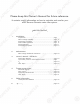
Please keep this Owner’s Manual for future reference. It contains useful information on how to maintain and care for your APEC Reverse Osmosis water filter system. TABLE OF CONTENT 1. Installation: 2. Maintenance: 3. Owner’s Manual - RO Basics: 4. Trouble-shoot Guide: T 5. Other Information: 6. W Warranty ........................................................................... page 37 Preparation ................................................................... Filter housings assembly ...
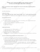
Thank you for choosing APEC reverse osmosis systems. You now own the finest water filter in America. Please read and become familiar with instructions and parts needed before proceeding with the installation. (This manual is constructed for standard APEC Essence ROES-UV75 System.) BEFORE INSTALLATION: Inspect the system: Please take the system and all the components out of the box. Inspect the system and all the connection fittings carefully, make sure nothing is damaged during shipping.
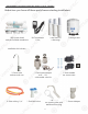
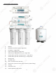
Components p included with the ROES-UV75 system: y Make sure you have all these parts before starting installation.
Component p Itemization: 1) Bracket 2) Membrane and housing (4th-stage filter) 3) UV Light (5th-stage filter) 4) Inline carbon filter (6th-stage filter) 5) Sediment pre-filter and housing (1st-stage filter) 6) Carbon block pre-filter and housing ( 2nd-stage filter) 7) Carbon block pre-filter and housing ( 3rd-stage filter) 8) Storage tank 9) Tank ball valve 10) ASO – Automatic Shut Off valve 11) Check valve (Internal check valve encased in plastic fitting) 12) T-fitting 13) Feed wa
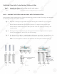
THERE ARE TWO PARTS TO INSTALLING THE RO SYSTEM: Part I. Part II. Note: Assemble the filters and housings onto the main system Installing the system The RO Membrane Element has already been pre-installed. PART I. ASSEMBLE THE FILTERS AND HOUSINGS ONTO THE MAIN SYSTEM Remove plastic/paper wrappings on the 3 filters and housings, put filters into the 3 housings, and assemble the housings onto the main system as follows: Fig. 1 Stand the 3 housings upright.
PART II. INSTALLING THE SYSTEM Space: Make sure there is sufficient space under the counter for installation (an area of about 17”L x 6”W x 18”H for the system, 11”D x 18”H or L for tank). The pressurized tank can be installed on its side to save space. The RO system is best installed under the kitchen sink.
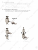
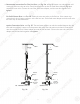
Fig. 4A - Needle Valve Installation. Attach the needle valve (C) to water supply adapter (A). Please apply 5-6 wraps of teflon tape to needle valve prior to connecting it to the water supply adapter (A). Fig. 4B - If your pipe has a 1/2” Connection. By attaching the 1/2” x 3/8” converter (B) to the Male end of the water supply adapter (A), you now have a 1/2” Male and Female water supply adapter. Fig. 4C - If your pipe has a 3/8” Connection.
3. Recommend Connection For Flex Line Riser: See Fig. 5A. & Fig. 5D Loosen nut and separate cold water riser tube from shut off valve. Gently bend riser tube so that the Feed Water Adapter (Fig 4) fits onto the shut off valve. Connect the riser tube, feed water adapter, and shut off valve together and tighten. For Solid Copper Riser: See Fig. 5B. Follow the same procedure as for flex line. If the copper riser cannot bend, this it’s best to replace it with a flex line riser.
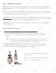
Fig. 5C Fig. 5D Fig. 5E 4. Needle Valve: See Fig. 5C. Screw the Needle Valve onto the Adaptor tightly. Apply 6-8 rounds of Teflon tape onto Needle Valve before attaching it to the Adaptor. To open needle valve: To close needle valve: T Turn needle handle counter-clockwise. T Turn needle handle clockwise. Test for leaks at this point: p Close the Needle Valve (turn needle handle clockwise all the way in to close). Turn ON the cold water supply to the sink faucet.
Step 2: Drain Saddle Installation Note: To avoid p possible drainage g noise,, mount drain line as low as p possible on the vertical tailpiece, p , or on horizontal tailpiece. p There is constant water pressure “packed” inside the RO system which blocks the discharge water from backing-up into the system. So the discharge water is “forced-drained”, not “gravity-drained”. 1. See Fig. 6. The drain saddle assembly should be installed above the trap and on the vertical or horizontal tailpiece.
3. See Fig. 8, 8A. Make sure to align g the drain saddle hole to the drilled hole perfectly. perfectly p y y. Mis-aligning these two holes will block the drain water and cause membrane damage. Attach the drain saddle to the drain pipe and tighten the two screws evenly. 4. Once the drain saddle is secured, push 1/4” black drain tubing into the Quick Connect fitting on the saddle. DO NOT use a “Insert” on the drain tubing. Fig.
3. For Porcelain Sink: Porcelain enameled sinks can readily be chipped if care is not exercised when drilling the hole. Before starting the drill motor, apply firm downward pressure on the bit until a crunching occurs. This will help keep the drill bit from walking when starting the hole. A small pilot hole will also aid the drill bit. Note: Immediately after the hole drilling is done, clean up all metal chips, for metal chips will stain the porcelain!! Step 4: Mounting The Faucet 1.
Step 6: Connecting The System Fitting Types: There are 2 types yp of fittings g provided p for connecting g the system y 1. Metal compression nut fitting (comes with 1 insert, 1 sleeve, 1 nut) Fig. 10 How to connect: - See Fig. 10. Slide the compression nut onto the tubing. - Slide the plastic sleeve onto the tubing. - Insert the “insert” into the tubing. - Insert the tubing into the opening of the fitting. - Slide the brass nut up, then tighten nut with a wrench.
Depending on your system model, there will be 2 types of protective end plugs. Both types of end plugs are disconnected the same way. After disconnecting the end plugs, please discard them as they are not needed for installation. 2 Types of End Plugs Soft Plug Hard Plug To Disconnect the End Plugs: g Push In and Hold Down on the collet ring square against the fitting. While holding down the collet ring, pull out the end plug with your other hand. Only the plug will slide out from the connection.
Option Op ption 1 Diagram DRINKING WATER A FAUCET Z SINK INPUT WATER A WASTE WATER A W 6th Stage 5th Stage 4th Stage DRINKING WATER A TTO ICEMAKER OPTION H Fig.
3. Point W - Discharge water connection: Tubing color: Black tubing. Connect the BLACK tubing from the RO to the Drain Saddle. Fitting type: Quick Connect. Simply push Black tubing into the Quick Connect Fitting. No Insert, Sleeve or Nut needed here. See Fig. 10A (Page 12) 4. Point A - System water inlet (to Stage-1 pre-filter) connection: Tubing color: Red tubing. Connect the RED tubing from the Feed Water Valve to the RO’s stage -1 pre-filter. Fitting type: Quick Connect fitting See Fig. 10A (Page 12).
Option: p Ice-maker Connection If you want to connect product water from the RO to your ice-maker, you will need: x One T-fitting, preferably the quick-connect type fitting x One x Extra x Extra 1/4" tubing long enough to go from the RO system to your ice-maker x Optional: x Optional: One shut-off valve, preferably the quick-connect type. type. See Fig.13.
Step 7: System Start-Up 1. T Turn on feed water: Slowly, turn on your Cold water supply. Open the Needle Valve (turn counterclockwise) to allow the raw water to enter the system. Check for leaks! 2. Open tank valve: Open the tank’s ball valve to allow water to enter the tank. The tank’s valve is “On” when the valve handle is parallel (in the same direction) with the valve’s outlet (see Fig. 12). Check for leaks! 3. UV Light: Please attach the UV Transformer to the UV light, then to power outlet.
ESSENCE RO SYSTEM MAINTENANCE SCHEDULE The system requires very little maintenance. Just change the filter cartridges regularly as suggested below. Keep the system indoors away from extreme hot or cold temperatures, and run the system within its reasonable output capacity (i.e. allow the system to rest at least a few hours a day). To ensure the longevity and integrity of your drinking water system, please use genuine APEC Water replacement filter at www.freedrinkingwater.com/parts.
3) Discard 3 used filters, wash housings with mild soap, rinse off. Put 3 new filters into their respective housings: sediment filter in stage-1, carbon block filters in stages 2 & 3. 4) Close up the housings. Make sure each housing has a black O-ring in the thread groves. Use wrench to tighten each housing.
5) Check for leaks! 6) Drain the first tank of water (through faucet) to flush out the new membrane! The 2nd tank of water is ready for use. K H J Fig. 14A Fig. 14B How to Replace Stage-6 Carbon Filter: Replace this last filter at the same time you replace the stage-4 membrane. 1) Remove the OLD filter: See Fig. 14A. Disconnect the output tubing from point H and tubing at point K. To remove the tubing, push in and hold down on the collet ring square against the fitting.
How to Replace Stage-5 UV Bulb: Replace the UV light bulb after 1 year of service. After 12 months, the UV bulb loses its strength. Pro-longed use after 1 year will result in less than optimal performance. 1) Unplug the light Transformer from the power outlet. 2) Do not open the UV light housing. 3) Disconnect the Transformer’s adaptor and UV light’s adaptor at point M (Use Fig. 14C for reference). 4) Use a Flat Screwdriver and gently extract the light bulb on the flat surface at point N.
OWNER’S MANUAL Please read this section for useful RO system and maintenance information. TABLE OF CONTENT Part I: RO Basics Basic terms ................................................................................. page 23 System flow diagram ................................................................... page 23 Water pressure -- The most important factor ............................... page 24 Tank -- Fill up time. Fill up volume. Delivery pressure ...............
Part I: RO BASICS This section provides basic concepts on how an ROES system works, how it performs in relation to your house’s water condition. We hope this information helps keep your ROES system running at top performance for years to come.
3) Input Water Pressure – The Most Important Factor! RO systems run on water pressure. Therefore your water pressure has the most direct effect on how well your RO will perform. With sufficient water pressure (85 psi max.), your RO system will function well, give high output with high rejection rate, and fill up the storage tank quickly. 4) How Long Does It Take to Fill Tank? Depending on your water pressure, the standard tank will fill up in 2-3 hours.
7) Ice-Maker Inlet Pressure Requirement: If your ice-maker requires a minimum input water pressure of 20-30psi, you need to have at least 50+psi input water pressure going into your non-pump RO system. If your water pressure is under 50psi, the tank will not fill up enough, and the delivery pressure to your ice-maker may be sluggish and unstable. To boost output pressure, you can add a Permeate Pump to your RO system. 8) Feeding Multiple Outlets: Feeding the filtered water to multiple outlets is do-able.
11) Premature Membrane Failure: There are 4 common causes that lead to premature membrane failure: 1. Failing to replace the 3 pre-filters as frequently as needed: If you’re on city water: The over-depleted carbon pre-filters allow the chlorine to get through and damage the membrane. If you’re on private well water: The overloaded pre-filters allow excessive sediments and particles to get through and clog up the membrane surface. 2.
Part II: Trouble-Shoot Guide For Newly y Installed RO System y After installation, if you encounter any of the problems described below, please follow this guide to troubleshoot. In most cases, the problem is quickly solved by following this guide. ROES-UV75 System’s Head Diagram E 1 3 C 2 4 B K A H D F J G Fig.
1) No Water at Dispensing p g Faucet - Water supply is off —> Turn on the water supply, or open Needle Valve ( turn needle handle counter clockwise) - Tank’s valve is closed —> Turn tank valve to an “Open” position - Output line is crimped —> Remove crimp - Incorrect installation —> See Fig.11 (Page 13). Verify all line connections. - Tank defective, no pre-charge pressure —> Set tank pre-charge to 5-7 psi. - ASO connection Error —> See Fig. 17 to reconnect ASO to the correct connection.
2) Sluggish gg Flow At Dispensing p g Faucet - Insufficient water pressure (see “RO Basics” for explanation) —> Check water pressure. If too low for this chosen RO model, either increase your water pressure or add pump to RO system. - Input water to RO is blocked —> Make sure Feed water valve is fully opened and unhindered. - T Tank not filled yet —> Wait until tank is more filled, takes 2-3 hours average. - Low tank pre-charge pressure —> Raise tank pre-charge to 5-7 psi.
- Stages 1, 2, 3 pre-filters partially clogged, reducing the input water pressure in RO —> Check stage-1 filter to see if it’s very dirty. If this filter has turned brown or other color in just 1-3 months, that means your input water has very heavy sediments and other clogging agents. Need to replace stage-1 filter frequently.
Test#1: Can the RO system y shut off off? ? - Draw 2-3 glasses of water from spigot. RO will start making water to fill tank. - T Turn OFF the tank’s valve to mimic “tank full”. - If your RO feeds multiple output points (icemaker, r bathroom, etc), shut OFF those lines. - Wait W for 3- 5 minutes, then check to see if the waste water stops running. - Check discharge water by either “listening” or actually taking out the drain line to look at it.
7) Filter Housing g Is Leaking g If you are experiencing a leak from any of the pre-filter housings on the reverse osmosis system, the rubber O-ring may be defective. The filter housing must have an O-ring in order to seal properly. Please review the steps below to address a leaking filter housing. Please follow the steps below: Step 1. Shut off the feed water line to the RO unit. Turn off the tank ball valve by turning the Blue Handle on the tank ball valve 90 degrees. Step 2.
9) Pure water still tastes like Tap p water: The first thing to check would be if the reverse osmosis membrane was installed. The membrane is the heart of the RO unit and it is the component that removes most of the contaminants and impurities in the water. If the membrane is installed, please make sure the first 1-2 tanks of water have been completely flushed out. The new filters on your system needs to be flushed out before use.
Close Tank Taank Vaalve Valve Fig. 18 Tilt System Step 1 Step 2 Step 3 If the noise comes back, try the above procedure again another 2-3 times. Sometimes it takes several tries to get rid of all the air in the system. If the noise persists after a few days, that means there is air in your water source, or the current Check Valve is resonating with your water pressure and pipes, creating the noise. In this case, a new Check Valve will solve the problem. Contact APEC customer service for assistance.
OTHER INFORMATION AirGap Faucet Installation There are 3 colored tubings on your Air-Gap faucet. At the end of each 1/4” tubing there is a “Quick Connect” fitting. The Quick Connect fittings is used to connect the Pure and Discharge water line from the RO unit to the Air Gap Faucet. To connect the lines, simply insert each line into the fitting port tightly. Fig. 19 Fig. 20 Hook-Up: 1. Assemble the faucet: There is a plastic “filler tube” in the slot next to the faucet’s on/off black lever.
How discharge water is disposed via Air-Gap faucet: Discharge water is routed through the Air-Gap faucet prior to being drained off into the standard drainpipe outlet. The 1/4” BLACK K waste water line from the RO system will discharge through the 1/4” RED line to the Air-Gap faucet. The drain water will then flow back down the 3/8” BLACK discharge water line of the Air-Gap faucet to your drain pipe.
LIMITED PRODUCT WARRANTY Scope p APEC takes pride in selling a superb line of products, including this reverse osmosis system (“Product”). As such, APEC expressly warrants to the original purchaser that, for a period of one (1) year from the date of purchase, the Product will be reasonably free of defects in materials and workmanship.
CONDITIONS THAT RENDER THIS LIMITED PRODUCT WARRANTY VOID THIS LIMITED PRODUCT WARRANTY SHALL BE VOID IF: 1. The Product is not operated in compliance with normal municipal water conditions for which the particular model of this Product is intended. 2. The person seeking to invoke the warranty is not the original purchaser. r That is, this Limited Product Warranty only extends to original purchasers. 3. The product is purchased used. That is, this Limited Product Warranty only covers new products. 4.
Advanced Purification Engineering Corp. 1320 S Johnson Drive City of Industry, CA 91745 For questions or comments please visit our website at: www.FreeDrinkingWater.com For technical support contact us at: Techsupport@freedrinkingwater.