
Installation Guide


5
PART II. INSTALLING THE SYSTEM
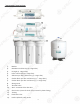
Space: Make sure there is sufficient space under the counter for installation (an area of about 17”L x
6”W x 18”H for the system, 11”D x 18”H or L for tank). The pressurized tank can be installed on its
side to save space.
The RO system is best installed under the kitchen sink. But if that is not feasible you can install the system
anywhere where there is a cold water supply with sufficient water pressure for the chosen RO model, and
an outlet to drain off the waste water from the system.
Mounting: No need to mount the RO system on the wall. The RO system can stand in the sink cabinet
without mounting, this makes future filter change easy and convenient. If you prefer to mount the system
to the wall, please make sure it can be taken down easily for filter replacement.
Feed Water: RO systems are designed to treat both hard and soft water and can handle incoming TDS
levels up to 2,000 ppm.
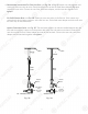
Fig. 4
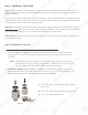
Step 1: Feed Water Connection
The RO system must be connected to the COLD water supply only!
1. Locate the Cold water supply valve under the kitchen sink (the round or oblong handle on
the right side). Turn off the incoming cold water completely by turning the shut off handle
clockwise.
Note: If the cold water shut off valve can not turn off the water, the main water supply
to the house must be shut off for the installation. Another option is to use a “self
piercing saddle valve” from APEC or from a local hardware store.
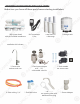
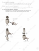
2. Feed Water Adaptor (1/2” to 3/8”): See Fig. 4. The Feed Water Adaptor comes with a
separate Needle Valve. The Adaptor goes inline onto your 1/2” or 3/8” cold water pipe. The
Needle Valve portion screws onto the Adaptor as shown in Fig. 4A.
A. 1/2” x 3/8” Male-Female Water Supply Adapter
with O-ring.
B. 1/2” x 3/8” Male-Female Converter with O-ring.
C. 1/4” x 1/8” Male Needle Valve.
5
PART II. IN
S
TALLIN
G
THE
S
Y
S
TE
M
Sp
ace
:
Make sure there is su
ff
icient space under the counter
f
or installation (an area o
f
about 17”L x
6
”W x 18”
H
f
or the system, 11”D x 1
8
”H
o
r
L
f
or tank). The pressurized tank can be installed on its
s
ide to save space.
The RO system is best installed under the kitchen sink. But i
f
that is not
f
easible you can install the system
anywhere where there is a cold water supply with su
ff
icient water pressure
f
or the chosen RO model, and
an outlet to drain o
ff
the waste water
f
rom the system.
M
ounting
:
No need to mount the RO system on the wall. The RO system can stand in the sink cabinet
without mounting
g
, this makes
f
uture
f
ilter change easy and convenient. I
f
you pre
f
er to mount the system
to the wall, please make sure it can be taken down easily
f
or
f
ilter replacement.
Feed Water
:
RO
sy
stems are desi
gn
ed to treat both hard and so
f
t water and can handle incomi
ng
TDS
l
evels up to 2,000 ppm.
F
i
g.
4
Step 1: Feed Water Connectio
n
The RO system must be connected to the COLD water supply only!
yppyy
1. Locate the
Co
l
d
water supply valve under the kitchen sink (the round or oblong handle on
the right side). Turn o
ff
the incoming cold water completely by turning the shut o
ff
handle
c
lockwise.
N
ote: I
f
the cold water shut o
ff
valve can not turn o
ff
the water, the main water supply
to the house must be shut o
ff
f
or the installation. Another option is to use a “sel
f
piercing saddle valve”
f
rom APEC or
f
rom a local hardware store.
2
. Feed Water Adaptor (1/2” to 3/8”
):
See
F
i
g. 4. The Feed Water Adaptor comes with a
s
eparate Needle Valve. The Adaptor goes inline onto your 1/2” or 3/8” cold water pipe. The
N
eedle Valve portion screws onto the Adaptor as shown in Fig. 4
A
.
A
. 1/2” x 3/8” Male-Female Water Supply Adapte
r
with O-ring.
B. 1/2” x 3/8” Male-Female Converter with O-ring.
C
. 1
/4
” x
1/
8” Male Needle Valve
.