
Datasheet


APEM www.apem.com G-15
G
A1-A01 series
Industrial controls
Installation - tools
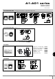
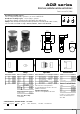
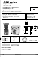
Modular construction / panel mounting
SWITCH BLOCK
F
IXING
NUT
PANEL
BULB
REFLECTOR
LOCATING
S
LOT
LEGEND
SCREEN
EMERGENCY
STOP
ROTARY
LEVER SWITCHES
KEYLOCK
SWITCHES
PUSHBUTTONS
& INDICATORS
LATCH
O
PERATOR
(.157 MAX)
4.00 Maxi
SEAL
P
OLARISING
DOT
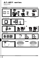
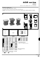
PANEL CUT-OUT
Round & square operators only
Rectangular operators only
Max. panel thickness : 8 mm (.315)
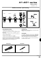
PANEL MOUNTING ASSEMBLY
• Drill/punch hole shaped as above.
• Assemble front operator through hole, fit fixing nut and
tighten to a maximum torque of 0,8Nm using tool
No 30-0001.
• Wire chosen switch block as required and slide onto
operator until latch engages.
• Fit bulb if required using tool No 30-0002.
• Snap screen onto reflector assembly with legend in
between if required and snap onto front operator TAKING
CARE TO LINE UP THE LOCATING SLOT WITH THE
POLARISING DOT, and not to damage the seal.
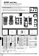
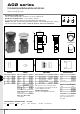
TO REMOVE BULB
Remove reflector/screen assembly. Use the bulb extractor
30-0002 to remove the bulb.
SWITCH BLOCK
To assemble switch block to front operator, TAKE CARE
TO LINE UP SWITCH BLOCK WITH FRONT OPERATOR.
Once in position, slide on to front operator. NB. : Ensure
latch is fully engaged correctly onto the switch block.
To remove switch block, depress the latch and slide the
switch block off the operator.
(.059)
(.285)
1
.50
Ø16.00
.000/+.011
0.00/+0.30
(
.629 DIA )
7.25
(.413)
(
(.078 DIA)
Ø2.00
1
0.50
1
(
.629 DIA )
0.00/+0.30
.000/+.011
Ø16.00
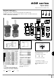
FIXING NUT KEY
30-0001
BULB REMOVER
30-0002