
Datasheet


KR series
Power rocker switches
Case - LEDs
APEM www.apem.com 9
C
2
5
3
6
1
4
+
-
-
+
4
1
6
3
5
2
B
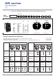
A (standard)
2
5
3
6
1
4
+
-
-
+
4
1
6
3
5
2
D - for function 1 (on-off)
with LED on side A
2
5
3
6
1
4
CKGRLA-B
+
4
1
6
3
5
2
2
5
3
6
1
4
+
4
1
6
3
5
2
-
-
-
+
+
-
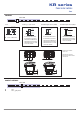
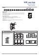
WIRING
The LED wiring diagram is shown on the case.
L
ED connected to the load
Independent LED or integrated functions
Note : If not available,
terminals are added to
connect the LED.
• For 6 terminal versions
G (standard)
2
5
3
6
1
4
CKRRLG-A
7
8
9
1010
9
8
7
-
+
4
1
6
3
5
22
5
3
6
1
4
7
8
9
10
-
+
+
-
-
+
• For 10 terminal versions
Please contact us for other wiring solutions.
2
5
3
6
1
4
CKGRLD-B
+
-
E
2
5
3
6
1
4
+
-
-
+
4
1
6
3
5
2
F
2
5
3
6
1
4
CKRRLF-A
+
-
-
+
4
1
6
3
5
2
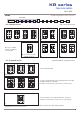
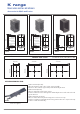
CASE + LEDS
To have independent LEDs.
H
+
-
+
-
10
9
8
7
4
1
6
3
5
22
5
3
6
1
4
+
-
7
8
9
10 10
9
8
7
CKRRLH-A
4
1
6
3
5
2
R2
R1
R2
R1
R2
R1
To obtain 2 symbol illumination levels (night illumination when OFF
and higher illumination when ON).
Dotted line = external wiring, continuous line = internal wiring
I
CKRRLI-A
10
9
8
7
4
1
6
3
5
2
To have a polarity inversion (typical application : fan motor).
Dotted line = internal wiring, continuous line = internal wiring
Available in Single Pole only, with H and J quick-connect terminals.
Power supply betweeen 2 and 5 - Load between 1 and 4 or 3 and 6.
Available with H and J quick-connect terminals.