
Operation Manual

9
P
(for S drive mechanisms only)
• Prise off the lampcover (17) over the light using a screwdriver.
• On the “LIMIT OF POWER” potentiometer (18), the upper limit of tole-
rance can be set. This is the amount of power, in addition to the pro-
grammed power, which may be applied, in order to open or close the
door. The maximum power between the door and the case may not ex-
ceed 150 N. At the left stop bolt of the potentiometer, the additional tole-
rated power is approximately 1.5 kg; at the right stop, it is 18 kg.
At the time of delivery, the power potentiometer is at the right-hand stop.
The control reads in the setting of the power potentiometer again on
every start.
Following changes to the power tolerance, it may be necessary to adjust
the OPEN and CLOSE end positions, if the desired position is not rea-
ched.
WARNING! For your own safety, the power tolerance should be kept
as low as possible to ensure that any obstruction s are recognized
rapidly and safely.
In the case of the L control unit, modifications can be made with the
service module (TorMinal (32)) are possible.
Q
• Check that the driver system can be stopped during opening and closing
movements, by a light press of the hand against the door, at a height of
100 mm above floor level. During the descending movement, the drive
system should change direction, moving the door approximately 100
mm in the opposite direction.
N.B: Garages with only one point of entry must be fitted with a
bowden cable for emergency unlocking (from the outside) if there is
a power failure.
III. CONTROL UNIT
P
Cancelling Power Values
• Once the drive has been installed and connected up to the mains supply,
the integrated light flashes indicating that the drive has still not “learned”
any power values. If the light fails to flash because the drive has already
learned power values – e.g. in the course of tests carried out under no-
load conditions – these values must first be cancelled.
• Prise off lamp cover (17) with a screwdriver. Using a narrow-pointed ob-
ject, hold down the button (20) (marked “T 1”) for approx. 5 seconds. As
soon as the power values are cancelled, the light goes out. To learn the
power values, proceed as described under O.
Fit lamp cover.
P
changing the bulb in the control unit
• Pull out the mains cable (6) and loosen the lamp cover, using a screw
driver. Unscrew the bulb by turning it counterclockwise.
• Screw in a new bulb by turning it clockwise (24 V, 21 W, Ba 15 s).
R
CODE TRANSFER FROM REMOTE CONTROL TO RECEIVER
Note: the APERTO 868 S has only 1 radio channel (channel 1). The se-
cond radio channel is only needed for partial opening or 2-channel opera-
tion.
Sequence:
• Learning button (22) on drive mechanism/receiver
- for channel 1, press until LED (21) is lit, release button
- for channel 2 (APERTO 868 L and APERTO 868 LX), keep pressing
until LED (23) lights up, release button
• Press desired remote control button in the reception range of the recei-
ver. The remote control transmits the code to the drive mechanism/ radio
receiver.
- depending on which channel was selected, LED (21) or LED (23)
goes out (see above).
• The two above steps must be repeated for every additional remote con-
trol to be taught for this drive mechanism/receiver. A maximum of 112
memory positions can be occupied with a radio code, each remote con-
trol channel occupying one memory position.
Example:
- if only one button of different remote controls is to be taught, a total of
112 remote controls can be memorised.
- if two buttons of the remote control are to be taught in each case, only
memory capacity for 56 hand transmitters is available.
• The learning mode can be interrupted by pressing the learning key (22)
until no LED is lit.
R
CODE TRANSFER FROM REMOTE CONTROL TO RECEIVER
If a remote control is lost, all channels on the receiver must teach all re-
mote controls again for security reasons.
Sequence:
• Press learning key (22) on the drive mechanism/receiver and hold down
for 25 seconds until both LEDs (21) and (23) are lit:
- press and hold learning key (22)
- LED (21 or 23) is lit for 5 seconds, then flashes for 10 seconds and is
then lit again.
- after another 10 seconds (total 25 seconds), both LEDs are lit – all the
channels are cancelled.
- release learning key (22), the LEDs go out – cancelling process ends.
R
CANCELLING A CHANNEL FROM THE DRIVE MECHANISM/RADIO
RECEIVER
For channel 1
• Press learning key (22) on the drive mechanism/receiver until LED (21)
is lit and hold this down for 15 seconds:
- press and hold learning key (22)
- LED (21) is lit for 5 seconds and then flashes for 10 seconds.
- as soon as LED (21) is lit again, release the learning key (22)
- the LED goes out – cancelling process is ended.
For channel 2
• Press learning key (22) on the drive mechanism/receiver until LED (23)
is lit and hold this down:
- press learning key (22)
- LED (23) is lit for 5 seconds and then flashes for 10 seconds.
- as soon as LED (23) is lit again, release the learning key (22)
- the LED goes out – cancelling process is ended.
R
CANCELLING A BUTTON OF A REMOTE CONTROL FROM THE
DRIVE MECHANISM/RADIO RECEIVER
If a user moves house and would like to take his hand transmitter with
him, all the codes of the remote control must be cancelled from the radio
receiver.
CAUTION: For security reasons, every button and every button combinati-
on of the remote control should be cancelled.
Sequence:
• Press learning button (22) on drive mechanism/receiver and hold down
for 5 seconds until an LED (21 or 23) flashes (it does not matter which).
Press button or button combination on the remote control of which the
code is to be cancelled from the drive mechanism/radio receiver. LED
goes out – cancelling process ends.
• Repeat the process for all buttons or button combinations to be cancel-
led.
R
CHANGING BATTERY IN THE REMOTE CONTROL
Press remote control on the key-ring with a coin. Open the battery cover
flap downwards. Remove battery and replace with a new one (CR 2032)..
Note the correct polarity of the batter. Close the battery cover flap and
check function using transmit LED.
S
APERTO 868 S, CONTROL UNIT WITH CONNECTION FOR SAFETY
DEVICES
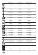
Connector (24)
• Permissible cable areas: max. 1.5 mm²
Pin allocation of the connector:
1 + 2 Transformer secondary 24 V (red)
3 C rail (green)
4 Chain (red)
5 + 6 keypad connection, further keypads can be attached in paral-
lel here
Terminal connections
• Additional connection options on the pluggable screw terminal (26) of
the control unit. Permissible cable cross-sections: max. 0.75 mm².
WARNING! The bridge at terminal 1+2 must be connected whenever
no safety control unit is installed. If you connect a safety device take
out the bridge at terminal 1+2.