
Operation Manual

8
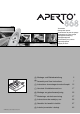
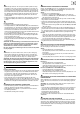
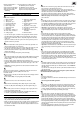
Refer to the illustrations 1 – 4 to check which type of door you have.
1) Sectional door no additional parts are required.
2) Up-and-over, tracked doors no additional parts are required.
3) Up-and-over, canopy door requires accessory bow arm converter
4) Hinged double doors reguires accossory hinged double
door fitting
I. ASSEMBLY ON THE FLOOR
A
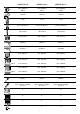
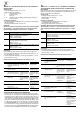
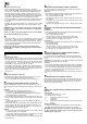
Parts shown in picture:
• Lay out all of the parts as shown on the garage floor, with the control
unit (4) inside the garage. Make sure the required tools are to hand.
• Always make sure that the chain is completely clipped into the black
chain case.
• Important – Make sure that all 3 parts of the chain guard are pushed
together so that they are flush.
B
• Push the motor with its chain (1) into one of the tracks (2). Make sure
that the contact springs are in the track.
• Push the other two tracks (2) as far as they will go onto tracks (3) until
the stop lugs resist. This produces a single, continuous track.
• Push the red switch marked ‘‘H’’ (9) into the track with the tip pointing
towards the motor (1).
• Push the chain through the opening in the switch (9).
C
• Insert the bolts (11a) into the ceiling support (11b). Mount the angle iron
(11c) onto the ceiling support (11d) using the nuts (11e) and locking
washers (11b).
• Push the ceiling support (11b) into the track, from the rear.
• Using the chain joint (5), connect the chain to the bolt on the control unit
(4). Push the control unit from the rear into the track (2), as far as the
stop.
• Important – the wiring grommet must be located at the bottom of the
control unit (4).
D
a
a Push the red switch marked ’’V” (10) into the other side of the track.
b
b Hang the clamping element (14a) to the chain and
c
c turn 90° around
d
d Push the plug in unit (13) into the track and push the clamping element
(14a) throught
Fit the washer (14b), the spring (14c) to the bolt (14d).
E
• Tighten the chain as far as the mark (arrow) is reached.
F
• Attach the two roof/wall angle irons (15a) using the screws (15b)
and the nut (15c) to the lintel fitting (13), but do not tighten fully yet.
G
• If the motor (1) does not run free, disengage it by a single pull on the
emergency unlocking device (16).
• Fit the door bracket (12a) and the pulley arm (12b) to the motor (1)
as shown, using the bolt and retaining clip (12d).
II. FITTING THE DRIVE TO THE GARAGE ROOF
• Turn the whole assembled unit so that the opening in the track is facing
down. Unlock the door and disconnect all of the locking devices so that
they cannot interfere with the movement of the door.
• Make sure that the garage door runs smoothly over its complete travel in
both directions. The door must be force-balanced, and should stay in
any position. If required, the door should be adjusted before the assem-
bled drive unit is fitted.
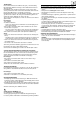
H
• Measure the centre of the garage door and mark it on the face of the
door and also on the lintel above the door.
• Open the door slowly and note where it comes closest to the roof
(including the rubber strip, where fitted). This point (the highest point of
the door’s travel) must be at least 40 mm from the roof.
The distance between the highest point of the door’s travel and the
bottom of the C-track must be at least 5 mm and no more than 65 mm.
NOTE: the pulley arm must be at a max. angle of 30°.
Close the door.
I
• Depending on the space available, the drive assembly can be mounted
on the lintel (frame) or the roof (as close to the lintel as possible). Mark
and drill holes 74 mm to the right and left of the middle of the door and
20 – 50 mm above the highest point of the door’s travel (10 mm
diameter holes for concrete, 5 mm diameter for wood).
• Important – take the thickness of the lintel or roof into account!
• Insert plugs (15d), raise the drive assembly at the front and secure the
angle irons (15a) using the wood screws (15f) and washers (15e).
J
• Raise the drive assembly at the rear and support on a ladder.
• Push the motor backwards. The gap between the control unit (4) and
the roof bracket (11c) can be adjusted to anything between 0 – 600 mm
depending on the particular garage roof. Adjust the roof bracket (11c)
vertically to ensure that the door does not rub against the track in its
travel and adjust the assembly to the centre of the door at the same
time. Mark the holes and drill (in concrete 10 mm diameter, in wood
5mmdiameter). Insert plugs (11f) and secure the roof bracket (11c)
with the screws (11h) and washers (11g).
• Important – take the thickness of the lintel or roof into account! If requi-
red, the projecting ends of the angle irons can be cut off with a hack-
saw.
K
• Close the door again. Fully tighten the screw (15b) and the nut (15c).
Push the motor (1) forward towards the lintel. Hold the door bracket
(12a) in position on the door and centre it. The angle can be fitted to the
door bracket in a variety of ways, depending on the type of door. Predrill
5 mm diameter holes. Secure the door bracket (12a) with the four
screws (12e). If required, other screws than those supplied may be used
to ensure the bracket is secure.
L
• Install the internal wall switch. The operator must have an unobstructed
view to the door. Do not attach the key set within the area of motion of
the door. Attach wall switch (8) at a suitable location, at least 1600 mm
from floor level.
Lay the two-core cable (8) and connect up the white and brown wires to
the wall switch (8).
NOTE! Never install the control cable alongside a power cable, this
can interfere with the control system.
M
• Put plug in wall socket.
• The distance from the socket to the controller housing must not exceed.
0.5 metre.
Observe applicable VDE regulations.
N
• Push switch ‘‘V” (10) right up to the motor (1), until the quiet click of the
switch is audible and tighten the retaining screw. Open the door fully.
• Push switch ‘‘H” (9) right up to the motor (1), until the quiet click of the
switch is audible and tighten the retaining screw. Connect the motor (1)
by a single pull on the emergency unlocking device (16).
O
• Plug in the mains cable (6). The light must flash. (If the light fails to
flash, refer to the section on “Cancelling Power Values”). To allow it to
“learn” the correct power values, the drive must operate through a com-
plete opening and closing cycle to ensure that it registers the required
power for both directions of travel. The drive can be activated for this
purpose by pressing the wall switch (8) or using the remote control (19).
The integrated light flashes during this learning procedure. The light only
remains on permanently when the required power has been learned for
both directions.
• Check the end positions for opening and closing. If needed, install a
limit switch (9/10) for the open and closed end positions.
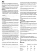
1 Motor and chain
2 Tracks, 3 pcs
3 Track joints, 2 pcs
4 Control unit with lamp
5 Chain joint, 3 part
6 Mains supply cable
7 Wall switch cable
8 Wall switch
9 Rear switch, marked, “H”
10 Front switch, marked, “V”
11 Ceiling support
12 Pulley arm, door bracket,
bolt, retaining clip
13 Plug in unit
14 Clamping element, washer,
spring, screw
15 Angle iron, screws, plugs
16 Emergency unlocking device
17 Lamp cover
18 Pulling force adjustment
transmitter
19 Remote control