
Service manual

APEX — Installation and Service Manual 41
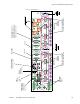
Expanded (Multi-Chassis) Systems
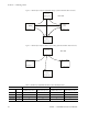
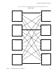
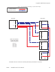
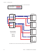
Figure 9. Apex Plus Master Clock Cabling - Systems with 512 Inputs
Frame 0
Frame 4
MC A
OUT
OUT
OUT
IN
MC B
OUT
OUT
OUT
IN
MC A
OUT
OUT
OUT
IN
MC B
OUT
OUT
OUT
IN
Frame 5
MC A
OUT
OUT
OUT
IN
MC B
OUT
OUT
OUT
IN
Frame 6
MC A
OUT
OUT
OUT
IN
MC B
OUT
OUT
OUT
IN
Frame 7
MC A
OUT
OUT
OUT
IN
MC B
OUT
OUT
OUT
IN
Master Clock Distribution
For Apex Plus Systems
with the following sizes:
512 X 512
512 X 1024
512 X 1536
512 X 2048
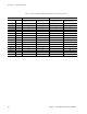
Input frames Output frames
1-512
1-512
513-1024
1025-1536
1537-2048
Note: Master Clock "Out" connectors are functionally identical (they can be attached to any chassis).
Primary connections
Redundant connections