
Automobile Parts User Manual

5
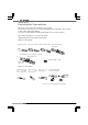
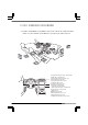
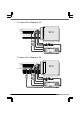
■ECU Arrangement Diagram
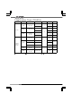
●Perform installation by referring to the symbols in the corresponding
columns of the tables of applicable models on and after page 10
A
B
C
D
E
F
G
H
I
J
K
P
L
M
N
O
A : Lower part of the passenger seat dash side
B : Right side of the glove box
C : Foot position of the passenger seat
D : Inner part of the glove box
E : Inner part of the center console
F : Under the driver’s seat
G : Under the passenger seat
H : Near the steering column
I : Left side of the meter panel
J : Lower part of the driver’s seat dash side
K : Left side of the center console
L : Engine room
M : Before the rear trunk
N : Behind after the driver’s seat
O : Behind the passenger seat
P : Upper inner part of the center console