
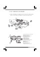
Automobile Parts User Manual

7
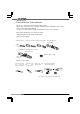
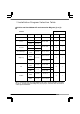
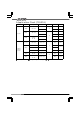
■Installation Diagram Selection Table
●Vehicles not listed below will use Connection Diagram (1) or (2).
HONDA
Speed Limiter
Name Type Engine Year
Note
s
CUT RETAIN
S2000 AP1
F20C
‘
99
.
4∼
‘
05
.
10
3
1
Torneo
CF4
F20B
‘
97
.
9∼
‘
00
.
5
A/T
4
1
CF3
F18B
Accord
CF4
F20B
‘
97
.
9∼
‘
00
.
5
A/T
4
1
CF3
F18B
Accord Wagon
CF7
CF6
F23A
‘
97
.
10∼
‘
02
.
10
4
1
Odyssey
RA7
RA6
F23A
‘
99
.
12∼
‘
03
.
9
4
1
RA4
RA3
‘
97
.
10∼
‘
99
.
11
Fit
GD4
GD3
L15A
‘
02
.
9∼
‘
07
.
9
4
1
GD2
L13A
‘
01
.
7∼
‘
07
.
9
GD1
‘
01
.
6∼
‘
07
.
9
Fit Aria
GD9
GD8
L15A
‘
02
.
12∼※
4
GD7
GD6
L13A
1
02
.
12∼
‘
05
.
9
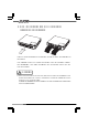
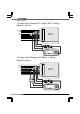
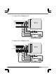
When connecting the IG Power, Engine RPM, Ground, Vehicle Speed signal wires to the ECU,
be sure to check the Connection Diagram (1)-(4) for proper connection. Also check P16 for
vehicle specific information.