AUTOMATION P R O D U C T S G R O U P, I N C. Operator’s Manual AGV-1000 Rev. A3, 10/08 Doc. 9002669 Automation Products Group, Inc. APG...Providing tailored solutions for measurement applications Tel: 1/888/525-7300 • Fax: 1/435/753-7490 • www.apgsensors.com • E-mail: sales@apgsensors.
AGV-1000 Rev. A3, 10/08 Table of Contents Warranty ......................................................................................... 3 Introducing ...................................................................................... 4 Understanding Ultrasonics ............................................................. 5 Mounting ......................................................................................... 7 Wiring ...................................................................
Rev. A3, 10/08 AGV-1000 • Warranty and Warranty Restrictions APG warrants its products to be free from defects of material and workmanship and will, without charge, replace or repair any equipment found defective upon inspection at its factory, provided the equipment has been returned, transportation prepaid, within 24 months from date of shipment from factory.
AGV-1000 Rev. A3, 10/08 • Introducing The AGV-1000 ultrasonic collision avoidance system is designed to provide a flexible solution for automated vehicles and other collision avoidance applications. The system can be configured with up to six transducers (standard), with the option of up to eight transducers for a wide coverage area. The AGV-1000 is designed with the following features: • Short and long range modes, each with eight programmable “SLOW” and “STOP” functions.
Rev. A3, 10/08 AGV-1000 • Understanding Ultrasonics Ultrasonic sensors measure distance using a transducer to send out ultrasonic bursts. Each burst contains a series of 1-20 pulsed sound waves that emit in the shape of a cone, reflect off the target, and are received by the sensor. The time required for the sound burst to travel to and from the target is converted into a distance measurement by the sensor.
AGV-1000 Rev. A3, 10/08 Distance The shorter the distance from the sensor to an object, the stronger the returning echo will be. Therefore, as the distance increases, the object requires better reflective characteristics to return a sufficient echo. Size A large object will have a greater surface area to reflect the signal than a small one, therefore, a large target will be detected at a greater distance than a small target.
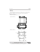
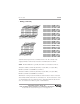
Rev. A3, 10/08 AGV-1000 • Mounting The AGV-1000 utilizes thru-hole type mounting for the controller and the transducer assemblies. See the drawings below for the mounting hole dimensions and spacing. NOTE: Drawings not shown to scale. 6.00" Controller Housing 6.70" 8.00" 1.75" 2.94" 0.25" 7.00" Transducer Bracket 3.00" 1.825" 0.1875" 1.70" 3.375" Automation Products Group, Inc. APG...Providing tailored solutions for measurement applications Tel: 1/888/525-7300 • Fax: 1/435/753-7490 • www.
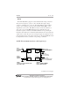
AGV-1000 Rev. A3, 10/08 • Wiring The AGV-1000 utilizes plug and socket terminal-block wiring connections. The system is designed to operate on 10 to 30 VDC. The supply voltage connects to terminals 1 & 2 or 11 & 12. The AGV-1000 has six “Front-End” circuits, each controlling a transducer. The terminals labeled FE(+) on the diagram below, refer to the “Front End” circuits. Connect the transducer (+) wires to the corresponding FE terminals. The T(-) terminals refer to the transducer negative connections.
Rev.
AGV-1000 Rev. A3, 10/08 • Programming The AGV-1000 is designed to be programmed through an RS-232 interface to a PC serial port. The “interfacing software” is used to send and receive a “setup file” which is used to edit the parameters of the sensor. The “setup file” is in a simple text format, and is easily edited using a text editing program like Microsoft “Notepad” or “Word”. Programming Steps: 1. Run the setup file in the floppy disk #1 that came with the AGV-1000.
Rev. A3, 10/08 AGV-1000 • Parameters VERSION NUMBER (0 to 65535) Allows the user to assign a “version number” for tracking and referencing different setup files. FILE TYPE (User defined) Allows the user to assign a “file- type” name for tracking and referencing different setups. TI GAIN (0-8) Sets the maximum gain/amplification level that is applied to the return signals on all of the Front-End circuits. The “Front-Ends” are the circuits that control the transducers.
AGV-1000 Rev. A3, 10/08 then receives 7 more consecutive error readings the counter would reach 10 and an error condition would then be output. STOP ON ERROR (0=NO & 1=YES) If this parameter is set to 1 (YES), the AGV-1000 will output a “stop” command if the “FAULT” parameter error-limit is reached. SLOW ON ERROR (0=NO & 1=YES) If this parameter is set to 1 (YES), the AGV-1000 will output a “slow” command if the “FAULT” parameter error-limit is reached.
Rev. A3, 10/08 AGV-1000 RANDOM PULSE 1-6 (0 to 120 msec.) The RANDOM PULSE parameters are used to set delays between samples from each of the six front-end circuits. By assigning varied delays between samples, the user can reduce transducer cross-talk and multiple-echo interferences. The default settings have been used with good results and should not need adjustment in most applications.
AGV-1000 Rev. A3, 10/08 • Inputs The AGV-1000 has four discrete inputs. Inputs 1 to 3 are used in combination to select between different setups. Input 4 is used to select between LONG and SHORT operating ranges. By changing the “on/off” combinations of inputs 1 to 3, we are able to get the 8 different input options below.
Rev. A3, 10/08 AGV-1000 SLOW & STOP zones — (0 to 4.064 m) For each of the 8 combinations of inputs 1-3, the AGV-1000 also allows the user to program the length (in Meters) of the SLOW and STOP zones (see figure on previous page) If an obstacle is detected inside the SLOW or STOP zone, then the AGV-1000 will output a SLOW or STOP condition.
AGV-1000 Rev. A3, 10/08 • Outputs The AGV-1000 has four solid state relay outputs, rated at 130 mA maximum. WARNING! DO NOT EXCEED THIS RATING. If 130 mA is insufficient, the AGV-1000’s relays can be used to control external relays rated to handle your current needs. The four outputs are “Normally Open” relays that operate in the “closed” position. An error, a target, or power loss will cause the appropriate output(s) to open.
Rev. A3, 10/08 AGV-1000 • Specifications Detection Range .............. 0.229 m to 4.064 m (9 inches to 12.4 feet) Input Voltage .................... 10-30 VDC Inputs ............................... RS-232 and (4) discrete Outputs ............................ (4) solid state relays (130 mA max) and RS-232. Accuracy ......................... 0.25% of range Adjustments .................... RS-232 Total Current Draw: .......... TBA Transducer Type: ............. Electrostatic Operating Temperature: ....
AGV-1000 Rev. A3, 10/08 Notes Automation Products Group, Inc. APG...Providing tailored solutions for measurement applications 18 Tel: 1/888/525-7300 • Fax: 1/435/753-7490 • www.apgsensors.com • sales@apgsensors.
Rev. A3, 10/08 AGV-1000 Notes Automation Products Group, Inc. APG...Providing tailored solutions for measurement applications Tel: 1/888/525-7300 • Fax: 1/435/753-7490 • www.apgsensors.com • sales@apgsensors.
AUTOMATION P R O D U C T S G R O U P, I N C. APG...Providing tailored solutions for measurement applications Automation Products Group, Inc. Tel: 1/888/525-7300 1/435/753-7300 Fax: 1/435/753-7490 e-mail: sales@apgsensors.com www.apgsensors.com Automation Products Group, Inc. 1025 W. 1700 N.