AUTOMATION P R O D U C T S G R O U P, I N C. Operator’s Manual IRU-2xx4/3xx4 Series Rev. A2, 11/08 Doc. 9002673 Automation Products Group, Inc. APG...Providing tailored solutions for measurement applications Tel: 1/888/525-7300 • Fax: 1/435/753-7490 • www.apgsensors.com • E-mail: sales@apgsensors.
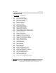
IRU-2xx4/3xx4 Rev. A2, 11/08 Table of Contents Warranty ............................................................................................................... 3 Understanding Ultrasonics ................................................................................... 4 Description ........................................................................................................... 5 Specifications ...........................................................................................
Rev. A2, 11/08 IRU-2xx4/3xx4 • Warranty and Warranty Restrictions APG warrants its products to be free from defects of material and workmanship and will, without charge, replace or repair any equipment found defective upon inspection at its factory, provided the equipment has been returned, transportation prepaid, within 18 months from date of shipment from factory.
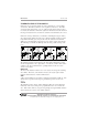
IRU-2xx4/3xx4 Rev. A2, 11/08 UNDERSTANDING ULTRASONICS Ultrasonic sensors measure distance by using a transducer to send out ultrasonic bursts. Each burst contains a series of pulsed sound waves. The ultrasonic burst emits in the shape of a cone, reflects off the detected target, and is received by the transducer. The time required for this burst to travel to and from the target is measured and converted into a distance measurement by the sensor.
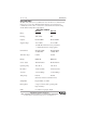
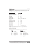
Rev. A2, 11/08 IRU-2xx4/3xx4 DESCRIPTION The IRU-2xx4/3xx4 is a low cost ultrasonic sensor used for non-contact measurement over a 1’ to 35’ range. RS-485 interface allows for convenient sensor communication. The sensor is encased in a sealed chemical resistant housing and has built in temperature compensation. SPECIFICATIONS Range: IRU-2xx4 1’ to 25’ IRU-3xx4 1.
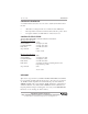
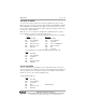
IRU-2xx4/3xx4 Rev. A2, 11/08 SETUP & OPERATION Wire the IRU-2XX4/3XX4 as described below. Color Red Black Orange Blue White Green Description + 12 - 24 VDC Ground T(+) or TD(A) T(-) or TD(B) NPN (200 ma max) Clock Sync. RS-485 COMMUNICATIONS DATA All Communication to the sensor is in the following format: Protocol Speed Length Stop Parity Echo T D(A ) T D(B ) GND GND +1 2 RS-232 to RS-485 Converter RS-485 2 wire 9600 8 bits 1 bit none on Orange Wire Blue Wire Automation Products Group, Inc. APG...
Rev. A2, 11/08 IRU-2xx4/3xx4 COMMAND PROTOCOL A command must be sent to the sensor in order to obtain any information from the unit. • • • All distances coming form the sensor will be in whole millimeters. The temperature is returned as a Celsius value with a 40° positive offset No negative numbers, decimal numbers or fractions are sent. COMMAND STRUCTURE All of the IRU-2XX4/3XX4 commands follow the format below.
IRU-2xx4/3xx4 Rev.
Rev. A2, 11/08 IRU-2xx4/3xx4 PARAMETERS The Parameters (E) command displays the current settings of the sensor. The following is an example of a parameter report from the IRU-2XX4/3XX4. PARAMETERS MENU Min. Max. Distance Sensor Number EE Bank Number EE Blanking EE Pulses EE Sensitivity EE Calibration EE Temp.
IRU-2xx4/3xx4 Rev. A2, 11/08 SENSOR NUMBER Up to 10 sensors may be attached to the same communication and power line. Each sensor is then assigned a unique number. Each sensor must have a unique Sensor Number. Sensor Numbers are assigned one at a time as the sensors are placed on line. When assigning these values, ensure that only the desired sensor is connected to the RS-485 line.
Rev. A2, 11/08 IRU-2xx4/3xx4 BLANKING Blanking allows the sensor to ignore all echoes returned before this distance. There is a minimum distance to which this can be set which is 152 millimeters. This distance (or time) allows the ceramic in the transducer to stop vibrating after it has transmitted a series of pules.
IRU-2xx4/3xx4 Rev. A2, 11/08 PULSES Pulses is used to control output power of the sensor. Each burst from the sensor contains a number of pulses. More pulses equate to more power and fewer pulses to less power. Caution: More power may not always be best as more pulses can create more echoes and may result in false readings.
Rev. A2, 11/08 IRU-2xx4/3xx4 SENSITIVITY Sensitivity controls the gain of the receive circuit. High values will amplify the return pulse enabling the sensor to detect weak signals. Caution: High sensitivity setting increases the chance for the sensor to detect unwanted objects, which can decrease the reliability of the output.
IRU-2xx4/3xx4 Rev. A2, 11/08 CALIBRATION Calibration The IRU-2XX4/3XX4 must be calibrated if a familiar reading is desired. The software is designed so that a calibration factor of 1000 will yield units that represent inches, feet and meters. Variations of the speed of sound in different atmospheres may yield readings which slightly differ from actual measured values. If this is unacceptable, vary the Calibration factor to “dial in” the exact number desired.
Rev. A2, 11/08 IRU-2xx4/3xx4 TEMPERATURE COMPENSATION Temperature Compensation allows the operator to enable or disable temperature compensation. When this feature is enabled, the IRU-2XX4/3XX4 will make adjustments for variations in temperature, which affects the speed of sound. This will produce a more exact output.
IRU-2xx4/3xx4 Rev. A2, 11/08 AVERAGE Average: The sensor will average the number of samples set in the Average Parameter. Each qualified sample is placed into a buffer and averaged with the previous samples to generate a steady output. A qualified sample is one that falls within the boundaries set in the Out of Range Span Parameter.
Rev. A2, 11/08 IRU-2xx4/3xx4 OUT OF RANGE SPAN Out of Range Span The Out of Range Span was designed to eliminate extraneous signals and noise. This Span or window changes with the distance of the average distance reading. This window will allow only readings that fall within its limits. If the target is suddenly changed outside of the window limits, the sensor will wait until a number or echoes specified in the Out of Range Count are received within a new window before updating the output reading.
IRU-2xx4/3xx4 Rev. A2, 11/08 OUT OF RANGE COUNT Out Range Count : indicates the number of consecutive samples outside the Out of Range Span that would need to be detected before the sensor recognizes them as legitimate samples.
Rev. A2, 11/08 IRU-2xx4/3xx4 SAMPLE RATE Sample Rate is used to control the burst rate. The number entered in this field represents the number of milliseconds between each burst.
IRU-2xx4/3xx4 Rev. A2, 11/08 TRIP POINT SETTINGS The IRU-2XX4/3XX4 has a programmable NPN trip point that is fully programmable for ‘BEGIN’ and ‘END’ points and ‘TYPE’ of operation. ( see page 20) The zero point of distance will be at the transducer, the relay trip points is programmed in millimeters.
Rev.
IRU-2xx4/3xx4 Rev. A2, 11/08 TRIP TYPES Automation Products Group, Inc. APG...Providing tailored solutions for measurement applications 22 Tel: 1/888/525-7300 • Fax: 1/435/753-7490 • www.apgsensors.com • sales@apgsensors.
Rev. A2, 11/08 IRU-2xx4/3xx4 CONTINUOUS TRANSMIT The IRU-2XX4/3XX4 can operate in two different modes: (0) Control mode were the sensor will begin and end transmitting when it receives a begin or end transmit or bank command. (1) Continuous transmit mode were the sensor will transmit as long as it has power.
IRU-2xx4/3xx4 Rev. A2, 11/08 STOP TRANSMIT SENSOR Stop Transmit Sensor allows the user to identify a sensor and have it start transmitting. This command controls a single sensor. To have sensor number 1 stop transmitting, use the command structure; Send AAh 01h, 21h 01h 00h 55h Start Byte Sensor Number Command NA NA End Byte START TRANSMIT BANK Start Transmit Bank allows the user to identify a bank of sensors and have them start transmitting.
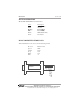
Rev. A2, 11/08 IRU-2xx4/3xx4 RESET PARAMETERS Reset allows the user to reset the parameters in a particular sensor to the factory defaults. To reset the parameters in sensor number 1, use the command structure: Send AAh Start Byte 01h, Sensor Number 1Fh Command 00h NA 00h NA 55h End Byte MOUNTING When mounting any ultrasonic sensor, alignment is critical. Ensure the face of the transducer is parallel to the target. A misalignment of a few degrees can affect the accuracy and reliability of the sensor.
IRU-2xx4/3xx4 Rev. A2, 11/08 1" NPT 2.751" 6" 3" NPT 1.190" IRU-3134 3.000" 6.183" 1.000" 1.000" IRU-2124 3.000" 3.600" 2.600" 3.000" 2.600" 1/2" NPT 1.000" IRU-2004 Automation Products Group, Inc. APG...Providing tailored solutions for measurement applications 26 Tel: 1/888/525-7300 • Fax: 1/435/753-7490 • www.apgsensors.com • sales@apgsensors.
Rev. A2, 11/08 IRU-2xx4/3xx4 Notes Automation Products Group, Inc. APG...Providing tailored solutions for measurement applications Tel: 1/888/525-7300 • Fax: 1/435/753-7490 • www.apgsensors.com • sales@apgsensors.
AUTOMATION P R O D U C T S G R O U P, I N C. APG...Providing tailored solutions for measurement applications Automation Products Group, Inc. Tel: 1/888/525-7300 1/435/753-7300 Fax: 1/435/753-7490 e-mail: sales@apgsensors.com www.apgsensors.com Automation Products Group, Inc. 1025 W. 1700 N.