AUTOMATION P R O D U C T S GROUP, INC. Operator’s Manual MNU series Ultrasonic Sensors Rev. B1 5/13 Automa!on Products Group, Inc. APG...Providing tailored solu•ons for measurement applica•ons Tel: 1/888/525-7300 • Fax: 1/435/753-7490 • www.apgsensors.com • E-mail: sales@apgsensors.
MNU Series Ultrasonic Sensors Rev. B1, 5/13 Table of Contents Warranty ........................................................................................ 3 Understanding Ultrasonics .......................................................... 4-5 Installa•on................................................................................... 6-8 Wiring ............................................................................................. 9 Sensor Communica•ons ....................................
Rev. B1, 5/13 MNU Series Ultrasonic Sensors • Warranty and Warranty Restric!ons APG warrants its products to be free from defects of material and workmanship and will, without charge, replace or repair any equipment found defec!ve upon inspec!on at its factory, provided the equipment has been returned, transporta!on prepaid, within 24 months from date of shipment from factory.
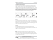
MNU Series Ultrasonic Sensors Rev. B1, 5/13 • Understanding Ultrasonics Ultrasonic sensors use a transducer to transmit bursts of ultrasonic sound waves. Each burst contains a series of pulsed sound waves that emit in the shape of a cone, reflect off the target, and are detected by the sensor. The #me required for the sound waves to travel to and from the target is converted into a distance measurement by the sensor.
Rev. B1, 5/13 MNU Series Ultrasonic Sensors Angle The inclina!on of the object’s surface in rela!on to the sensor face will affect the strength of the reflected sound waves. Surfaces perpendicular to the sensor will reflect more signal directly back to the sensor. If a surface is more than a few degrees off perpendicular, enough of the signal will be reflected away from the sensor that the target will not be detected.
Rev. B1, 5/13 MNU Series Ultrasonic Sensors • Installa!on Proper sensor moun!ng is cri!cal for successful opera!on of an ultrasonic sensor. Using the following guidelines can help ensure trouble free installa!on and opera!on: • Ensure that the sensor face is perpendicular to the target surface. If the target is more than a few degrees off perpendicular, it may not be detected. Targets at greater distances will require more precise sensor alignment.
Rev. B1, 5/13 MNU Series Ultrasonic Sensors • Always mount above the highest an!cipated target level by at least the published minimum blanking distance. If a target enters into the blanking area, error in the detec!on will occur. It is always advisable to allow for sufficient headroom to ensure that the target does not enter the blanking area. • Generally it is advisable to mount the sensor away from any vessel fill spouts.
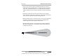
MNU Series Ultrasonic Sensors Rev. B1, 5/13 Stand Pipe Moun!ng Stand pipes are used to provide headroom at the top of a tank when the target is expected to come closer to the sensor than the minimum blanking distance. It’s very cri!cal that the stand pipe be installed perpendicular to the target. This is especially important on longer range applica!ons. The pipe must have smooth walls (no joints) and no burs or obstruc!ons. If possible, cut the end of the pipe at a 10°-45° angle (see drawing).
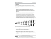
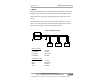
Rev. B1, 5/13 MNU Series Ultrasonic Sensors • Wiring Always use shielded cable. It is recommended that twisted-pair cable be used between sensors when connec!ng mul!ple sensors to the Modbus network. NOTE: Always use a high quality power supply that will deliver clean, stable voltage. The MNU series sensors are wired in a daisy-chain configura!on, as shown below. Each sensor should be connected individually and assigned a unique address before wiring the sensor into the Modbus network.
Rev. B1, 5/13 MNU Series Ultrasonic Sensors • Sensor Communica!ons The MNU sensor u!lizes standard Modbus RTU protocol (RS-485). The MNU sensor can only operate as a slave device. For more informa!on about Modbus RTU, please visit www.modbus.org.
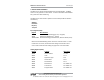
Rev. B1, 5/13 MNU Series Ultrasonic Sensors (con!nued) Register Func!on Value Range 40408 Sensi!vity 0 to 100 40409 Pulses 0 to 20 40410 Blanking 0 to 10364 mm 40411 Gain Control 0 to 4 40412 Averaging 0 to 100 40413 Filter Window 0 to 10364 mm 40414 Out of Range Samples 0 to 255 40415 Sample Rate 50 to 1000 msec.
MNU Series Ultrasonic Sensors Rev. B1, 5/13 Configuring So#ware Communica!ons Step 1: select “Communica#on” from the “Configure” menu. Step 2: select “MNU” from the Sensor Type menu, then click the “Save Config” bu"on at the bo"om of the screen. Automa!on Products Group, Inc. 12 APG...Providing tailored solu•ons for measurement applica•ons Tel: 1/888/525-7300 • Fax: 1/435/753-7490 • www.apgsensors.com • sales@apgsensors.
Rev. B1, 5/13 MNU Series Ultrasonic Sensors Step 3: set the mode of communica!on by selec!ng the . Select the appropriate Comm Port when using direct serial communica!ons. OR Check the “USB Communica!ons (RST-6001)” box when using the RST-6001 communica!ons module. Automa!on Products Group, Inc. APG...Providing tailored solu•ons for measurement applica•ons Tel: 1/888/525-7300 • Fax: 1/435/753-7490 • www.apgsensors.com • sales@apgsensors.
Rev. B1, 5/13 MNU Series Ultrasonic Sensors Configuring So#ware Communica!ons for Mul!ple Sensors Step 1: select the total number of sensors you wish to read. Step 2: change the “Sensor #” boxes to match the address’ of the target sensors. Step 3: Change the Descrip!on labels as desired. The Descrip!on is used to differen!ate between sensors in other areas of the so$ware. Step 4: Click “Save Config” then “Close”. (con!nued) Automa!on Products Group, Inc. 14 APG...
Rev. B1, 5/13 MNU Series Ultrasonic Sensors Step 5: Click on “Start”. The sensor readings should populate as the so"ware cycles through each sensor. START Step 6: Click on a sensor descrip!on to access that sensor’s parameters. Refer to “Using the So"ware Programming Window” on the next page for informa!on on adjus!ng sensor parameters. Automa!on Products Group, Inc. APG...Providing tailored solu•ons for measurement applica•ons Tel: 1/888/525-7300 • Fax: 1/435/753-7490 • www.apgsensors.
Rev. B1, 5/13 MNU Series Ultrasonic Sensors Using the So"ware Programming Window Click on the desired sensor descrip!on to open that sensor’s programming window. Sensor readings are displayed in the Input Registers table. The register values should automa!cally populate. If not, click “Receive All” to retrieve the register values from the sensor. (con!nued on next page) Automa!on Products Group, Inc. 16 APG...
Rev. B1, 5/13 MNU Series Ultrasonic Sensors To change an individual parameter, click on the value you wish to change, enter the desired value, then click the adjacent “Send” bu"on to implement the change. To send all the register values as currently listed, click “Send All” To retrieve the register values saved in a sensor, click “Receive All” A green window indicates successful communica!on. A yellow window indicates a communica!on failure.
Rev. B1, 5/13 MNU Series Ultrasonic Sensors • Parameter Descrip!ons Device Address (1 to 255) (40400) Each device within the Modbus network must be assigned a unique address. Each MNU sensor should be connected to the network individually and assigned an address. By default the each sensor is set to address 1. Units (1 to 3) (40401) Determines the unit of measure for the Calculated Reading (input registers 30303-30304) when in Applica!on Types 1, 2 or 7 (see below).
Rev.
Rev.
Rev.
Rev.
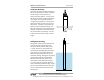
Rev. B1, 5/13 MNU Series Ultrasonic Sensors Applica!on Type 6: Volume of spherical tank (measurement result in register 30303-30304) Register Func!on Value Range 40402 Applica!on Type 6 40403 Volume Units 1 to 7 40404 Decimal Point 0 to 3 40405 Max Distance ≥ Empty Distance 40406 Full Distance Typically = Blanking Distance 40407 Empty Distance 0 to 10364 mm 40436-40437 Tank Diameter 0 to 100,000 mm Full Distance Empty Distance Diameter Automa!on Products Group, Inc. APG...
Rev. B1, 5/13 MNU Series Ultrasonic Sensors Applica!on Type 7: Pounds Allows the user to apply a conversion mul!plier to the calculated level reading. (measurement result in register 30303-30304) NOTE: the decimal place for the Mul!plier is always assumed to be in the thousands posi!on, therefore a se"ng of 206250 = 206.250 actual mul!plier. Example: suppose the product in a tank weighs 206.25 pounds for every inch of level. Assuming the Units are set to inches (Units = 2), the Mul!plier would be 206250.
Rev.
Rev.
Rev. B1, 5/13 MNU Series Ultrasonic Sensors Applica!on Type 11: Curve Fit (Strapping Chart) Allows the sensor to mimic a tank strapping chart by using a 3rd degree polynomial equa!on to produce a “curve fit” approxima!on.
MNU Series Ultrasonic Sensors Rev. B1, 5/13 Once the all data points have been entered, click the “Calculate” bu!on to determine the values required for the “curve fit” calcula#on. NOTE: before clicking “Calculate” ensure that there is only one empty row following the last line of data (as shown). Use the keyboard “Delete”key to remove any addi#on empty rows. Click the “Save to Sensor” bu!on to populate the appropriate Holding Resister fields (see below) and close the Strapping Chart window.
Rev. B1, 5/13 MNU Series Ultrasonic Sensors Volume Units (0 to 6) (40403) Determine the unit of measure for the volumetric Applica!on Types. 1 = Cubic Feet 2 = Million Cubic Feet 3 = Gallons 4 = Cubic Meters 5 = Liters 6 = Cubic Inches 7 = Barrels Decimal Place (0 to 3) (40404) Used to set the number of decimal places included in the Calculated Reading. The Calculated Reading will always be returned as a whole number. Example: a Calculated Reading of 1126.658 (gallons, "3, etc.
MNU Series Ultrasonic Sensors Rev. B1, 5/13 Sensi!vity (0 to 100%) (40408) Controls the level of amplifica"on applied the returning target echoes (signals). The sensi"vity se#ng is expressed as a percentage; 0 to 100%. When operating in Autosense mode, the Sensi"vity se#ng acts as an upper limit constraint (refer to Gain Control below for more informa"on on Autosense). Pulses (0 to 20) (40409) Controls the number of sound wave pulses being sent in each ultrasonic burst.
Rev. B1, 5/13 MNU Series Ultrasonic Sensors Filter Window (0 to 10364 mm) (40413) Sets the width of the target acceptance window. The target acceptance window is a zone, centered around the current target reading, within which any target detected will be considered legi!mate and figured into the averaging buffer. Any target detected outside of the Window will be considered “out of range” and will be ignored based on the se$ng in the Out of Range Samples parameter (see below).
MNU Series Ultrasonic Sensors Rev. B1, 5/13 Mul!plier (0 to 1999) (40416) Sets the conversion Mul!plier that will be applied to the sensor readings. The default is 1000 (see note below) and typically does not need to be adjusted. However, since the speed of sound is not constant through all environments, the mul!plier parameter allows the user to adjust for varia!ons in atmosphere when maximum accuracy is required.
Rev. B1, 5/13 MNU Series Ultrasonic Sensors •Web Alarming (40430 to 40435) When the MNU is interfaced with an LOE or RST-5002 web-enabled master device, it can be configured to generate website alarms via levelandflow.com (refer to the LOE or RST-5002 user manual for more informa#on about website alarms and using levelandflow.com).
Rev.
Rev. B1, 5/13 MNU Series Ultrasonic Sensors • Inspec!on and Maintenance The MNU series sensor requires li!le maintenance, but should be inspec"on periodically to ensure the sensor remains in good working order. Keep the sensor clean from heavy buildup on the sensing face. On models equipped with a micro-connector cable connec"on, ensure that the connec"on is securely "ghtened and sealed against the elements. Automa!on Products Group, Inc. APG...
MNU Series Ultrasonic Sensors Rev. B1, 5/13 • Specifica!ons Opera!ng Range MNU-5400: 4 to 72 in. (101 to 1829 mm) MNU-7400: 6 to 144 in. (150 to 3658 mm) MNU-6400: 10 to 180 in. (178 to 4572 mm) MNU-2400: 1 to 25 !. (305 to 7620 mm) MNU-3400: 1.5 to 40 !. (458 to 12192 mm) Opera!ng Voltage: 12-24 Vdc Opera!onal Current Draw: 35 mA @ 12 Vdc; 20 mA @ 24 Vdc Housing: PBT/Polycarbonate blend Moun!ng MNU-2424, 5424, 6424, 7424: 2 in. NPT MNU-3434: 3 in.
Rev. B1, 5/13 MNU Series Ultrasonic Sensors MNU-5414 2.0” 3/4” NPT 4.0” 1” NPT 3.06” MNU-5414-M 3/4” NPT 4.5” 1” NPT 3.06” Automa!on Products Group, Inc. APG...Providing tailored solu•ons for measurement applica•ons Tel: 1/888/525-7300 • Fax: 1/435/753-7490 • www.apgsensors.com • sales@apgsensors.
Rev. B1, 5/13 MNU Series Ultrasonic Sensors • Dimensions MNU-2424, 5424, 6424, 7424 2.0” 3/4” NPT 3.6” 2” NPT 3.06” MNU-2424-M, 5424-M, 6424-M, 7424-M 3/4” NPT 4.15” 2” NPT 3.06” Automa!on Products Group, Inc. 38 APG...Providing tailored solu•ons for measurement applica•ons Tel: 1/888/525-7300 • Fax: 1/435/753-7490 • www.apgsensors.com • sales@apgsensors.
Rev. B1, 5/13 MNU Series Ultrasonic Sensors MNU-3434 2.0” 3/4” NPT 3” NPT 5.52” 4.17” MNU-3434-M 3/4” NPT 3” NPT 6” 4.17” Automa!on Products Group, Inc. APG...Providing tailored solu•ons for measurement applica•ons Tel: 1/888/525-7300 • Fax: 1/435/753-7490 • www.apgsensors.com • sales@apgsensors.
AUTOMATION P R O D U C T S GROUP, INC. APG...Providing tailored solu•ons for measurement applica•ons Automa•on Products Group, Inc. Tel: 1/888/525-7300 1/435/753-7300 Fax: 1/435/753-7490 e-mail: sales@apgsensors.com www.apgsensors.com Automa•on Products Group, Inc. 1025 W. 1700 N.