320A Compellor Compellor ®® Owner’s Manual Dual Mono/Stereo Automatic Level Controller Manual P/N 999-0760 • Revision 2 • 09/30/03 Copyright 2003 Aphex Systems Ltd. All rights reserved. Printed in U.S.A. Written and produced by Donn Werrbach. S Y S T E M S 11068 Randall St., Sun Valley, CA 91352 U.S.A.
Fast Finder Contents 1 Quick Start 2 Introduction 3 Installation 4 Specifications 5 Operating Instructions 6 System Description 7 Warranty & Service Appendices 8 9 Safety Declarations CAUTION: For protection against electric shock, do not remove the cover. No user serviceable parts inside. WARNING: This equipment has been tested and found to comply with the limits for a Class A digital device pursuant to Part 15 of the FCC Rules.
20A Compellor 1. Contents 2. Quick Start - Page 6 3. Introduction - Page 7 3.1 What Is A Compellor? 3.2 What Does It Do? 3.3 How Does It Work? 3.4 A BIt Of Compellor History 4. Installation - Page 10 4.1 Unpacking 4.2 Damage & Claims 4.3 Main Voltage Selection 4.4 Power Cord 4.5 Mounting In A Rack 4.6 Proper Ventilation 4.7 Panel Security 4.8 Tools & Equipment Needed 4.9 Safety Considerations 4.10 Remote Connector 4.11 Reference Level Setting 4.12 Input Connections 4.13 Output Connections 4.14 Summary 5.
320A 1. Contents Compellor 6. Operation - Page16 6.1 Introduction 6.2 Recording 6.3 Mixing 6.4 Mastering 6.5 VIdeo Post Production 6.6 Sound Reinforcement 6.7 Live Concerts 6.8 Broadcast Radio Pre-processing 6.9 Broadcast STL/Phone Line Driver 6.10 Television Broadcasting and Cable Systems 6.11 Video and Audio Tape Duplication 6.12 Voice Processing 6.13 Hard Disk Recording 7. System Description - Page 20 7.1 Model Differences 7.2 Signal Flow 7.3 Processing Functions 7.4 Leveling Function 7.
Page 5
320A Compellor 2. Quick Start You can use this quick setup to get a signal through your Compellor right away. Then. you’ll want to go on and read through the manual to discover the wealth of information that is available to you. Quick Start 1. Make sure there is signal going through the Compellor with Process both “In” and “Out”. If not, check the input and output wiring. They may be reversed. Be sure to check for the correct input selection (analog or digital) on the rear panel.
3. Introduction 3.1 What Is A Compellor? A Compellor is the first and only product designed specifically for the transparent control of audio levels. While other audio processors are designed simply to compress and limit audio signals, a Compellor is designed to intelligently manage the dynamic range of audio without causing noticeable changes to the character and feeling of the sound.
320A Compellor 3. Introduction circuit. They thought that all audio processors should be noticeable. We had to explain that the unit was in fact working, and we asked them to listen to their mixes with and without the Compellor. After they did that, they were amazed at the results. Meanwhile, broadcasters were discovering the Compellor. They found it greatly enhanced their air chains. The Compellor soon won the favor of broadcasters internationally.
In 1994, Aphex introduced the current Compellor Models 320A and 323A. The model “A” revision signifies the inclusion of an improved patented Leveler circuit called the “Frequency Discriminate Leveler” (FDL) while all other aspects of the Model 320 remain the same. With the FDL, Compellors became even more transparent and useful than ever before. Now, in 2003 (as this manual is being written), the Compellor is still the most advanced and effective audio level controller available.
320A 4. Installation Compellor 4.1 Unpacking Your Compellor was packed carefully at the factory in a container designed to protect the unit during shipment. Nevertheless, Aphex recommends making a careful inspection of the shipping carton and the contents for any signs of physical damage. 4.2 Damage & Claims If damage is evident, do not discard the container or packing material. Contact your carrier immediately to file a claim for damages.
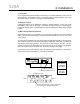
4.4 Power Cord The Compellor uses a standard IEC power cord set. The appropriate mains plug for each country is normally shipped with each unit. However, if you must install or replace the plug, Power Cord Color Codes USA Color Code Black = Hot (live) White = Neutral Green = Ground IEC/Continental Color Code Brown = Hot (live) Blue = Neutral Yellow/Green = Ground use the correct wiring code as follows: 4.5 Mounting In A Rack The Compellor occupies one standard 19 in. x 1 3/4 in. rack space (1RU).
320A 4. Installation Compellor Installation should be performed only by qualified individuals. It is the installer’s responsibility to insure his personal safety and the safety of others in the work area. It is never a good idea to work alone in the vicinity of high power electrical and radio frequency equipment. 4.10 Remote Connector Remote control, a feature of the Models 320A and 323A. 4.11 Reference Level Setting The Compellor should be normalized to match the operating level of your system.
The output impedance of 65 ohms is optimized for driving long cables and consequently a Compellor can drive just about any kind of line, balanced or unbalanced, of any length. Unique servo balanced output circuitry automatically maintains the proper gain and level into a balanced or unbalanced output line. Output connections are made by means of 3-pin male XLR jacks.
320A Compellor 5. Specifications 5.1 INPUTS Connector: Type: Impedance: Operating Level: Max input level: CMRR: 3 pin XLR female transformerless, servo balanced, RFI fIltered 22K-ohms balanced, 11K-ohms unbalanced user selectable +4dBu or -10dBV +27dBu(ref = +8), +25dBu(ref = +4), +10.8dBV(ref = -10) >90dB/100Hz, >70dB, 1KHz, >50dB, 20KHz 5.
5.6 RATIO Compressor: Leveler: Limiter: 1.1:1 to 3:1 program dependent 20:1 >30:1 5.7 ATTACK TIMES Compressor: Leveler, fast: Leveler, slow: Limiter: 5 to 50mSec program dependent 20Hz = 1.5 Sec > 1KHz Frequency Discriminate Leveler 20Hz = 5 Sec > 1KHz Frequency Discriminate Leveler 1 uSec 5.8 RELEASE TIMES Compressor: Leveler, fast: Leveler, slow: Limiter: 200 mSec to 1 Sec program dependent 3 Sec 10 Sec 200 mSec 5.
320A Compellor 6. Operation 6.1 Introduction The “Quick Start” guide in the front of this manual is the best way to begin using your Compellor. You will get a good feel for what is going on, and you will have a signal going through the processor, ready for fine tuning. We strongly recommend reading section 8 describing the Compellor’s features and controls in order to understand what all the settings mean.
has too wide a dynamic range, it can cause broadcast processors (if the processing does not include the Compellor) to work too hard and generate audible artifacts. These are all reasons to master a final mix which has a controlled dynamic range. The goal, of course, is to maintain the sound quality of the studio while you are trying to ‘tighten’ the mix. Adjust the Compellor for 2 to 4dB of gain reduction with the Process Balance at 11 o’clock. Stereo Enhance should be in and Leveling Link in.
320A Compellor 6. Operation numerous other devices which effectively control the level differences, but none have the transparency of the Compellor. These other devices, particularly multiband compressors and limiters, have a ‘sweet spot’ which renders the best results. Adjust the Compellor so that its output is driving the downstream processors at their sweet spot. 6.9 Broadcast STL/ Phone Line Driver The aural STL’s and phone lines have limited dynamic range.
6.13 Hard Disk Recording Transferring music to hard disk can be improved using a Model 320D. It is a known fact that CD’s are mastered at varying average levels with some strikingly lower or higher in volume level than others. When building a broadcast or webcast music library on a hard disk audio server, it would be nice to have a way to even out those levels so the on-air segues will always be smooth and fat. The Compellor can do that without adding artifacts across the whole inventory of titles.
320A 7. System Description Compellor - 7.1 Signal Flow The Compellor contains an input stage, an intermediate VCA stage, and an output stage. The input audio signal undergoes all processing in the VCA stage and is subsequently sent out through the output stage. A side chain system produces the control signals which change the VCA gain according to the signal processing requirements. 7.
7.4 Compressor Function The compressor cooperates with the leveler to supply more consistent program level control than possible with the leveler alone. While the leveler is relatively slow responding, the compressor works much faster to control both the transients and other quick changes in the sound level. The compressor has a variable compression ratio depending upon depth of compression. In other words, the ratio gets higher as more compression is used.
320A Compellor 7. System Description ground noise, but below the lowest program signal expected. Typically, a setting of -30dB (at about 9 o’clock) is satisfactory for all purposes. If, for some reason, you want to prevent the Compellor from bringing up program fades below a certain point, simply set the Silence Gate threshold to the level where you want the fade to become “uncorrected”. The Compellor will then freeze its automatic gain control and let the program continue fading out naturally. 7.
7.14 Output Control This control allows you to normalize the output level to 0VU after the processing is set up. It will usually get set around 12 o’clock, but there is a plus or minus 10dB range available which is useful if you need to match a slightly odd level. 7.15 Process Switch This operates a bypass relay which completely bypasses the Compellor in the process out mode. The relay will also go to bypass if the power is shut off or the power supply fails.
320A Compellor 7. System Description 7.19 Gain Reduction Metering When the Meter Select is toggled into “G.R.” the bi-color LED meter is programmed to indicate a bar graph from left to right but differing from the program level indications. In this case, the bar is entirely green except for a possible red dot which floats within the green bar. The entire length of the green bar indicates total gain reduction of the Compellor.
320A 8. Warranty & Service Compellor 8.1 Limited Warranty PERIOD One year from date of purchase SCOPE All defects in workmanship and materials. The following are not covered: a. Voltage conversions b. Units on which the serial number has been defaced, modified, or removed c. Damage or deterioration: 1. Resulting from installation and/or removal of the unit. 2.
320A Compellor Appendix A: Balanced and Unbalanced Lines and Operating Levels Interfacing all types of equipment with balanced and unbalanced lines and can sometimes be trouble some. First you have to somehow connect balanced to unbalanced and then you have to deal with dif ferent levels. This tutorial will teach you about the principles of balanced and unbalanced lines, wiring standards, and how to effectively interface them.
320A Compellor is cancelled out by the differential amplifier. Figure 1 illustrates how the hum is induced into both wires equally and therefore is cancelled out. Since the balanced line has wires that are twisted together, each wire tends to pick up the same amount of induction from external sources. Induction will create no significant voltage difference between the wires, hence the noise (or hum) will not be picked up by the differential input stage.
320A Compellor There are basically three ways to attack the prob lem of a ground loop. First is to eliminate it from its source, and the second is to re-route it through another path. The third is to balance out your unbal anced audio interfaces. Identify the Sources A good way to identify grounding problems is to use a multimeter to check the ac voltage between the chassis of your various gear when no audio cables are hooked up and all gear is plugged in and switched on.
Appendix C Appendix C: Proper Wiring Techniques A true balanced line should be used wherever your equipment allows. Use “twisted pair” shielded cable. For unbalanced wiring you should use high grade, low capacitance shielded wire for best results. If you have an unbalanced output but have a balanced input, the “pseudo-balanced” configuration may help deal with ground loop hum. This method and others are illustrated in Table 2. CONNECTOR WIRING STANDARDS The 3 pin XLR, 1/4” (63.
320A Appendix D Compellor TABLE 1 - BALANCED & UNBALANCED CONNECTOR WIRING STANDARDS 3-Pin XLR 1/4” TRS Phone Standard Wiring Convention (Balanced) Pin-1 Sleeve Ground/Shield (Earth, Screen) Pin-2 Tip Positive (Signal, High, Hot) Pin-3 Ring Negative (Signal Reference, Return, Low, Common) 1/4” TS Phone RCA Standard Wiring Convention (Unbalanced) Tip Center Pin Positive (Signal) Sleeve Shell Ground/Shield (Signal Reference/Return) audio line from a low impedance and receive into a hig
Appendix D output circuit. We strongly recommend that you refer to your various equipment manuals to find out what is used in each case before hooking up to unbalanced lines. XLR to XLR When connecting a balanced output to a balanced input, however, you don’t need to know what kind of balanced output you are dealing with. Simply treat it generically. OK for Microphones Standard store-bought cable. Shield grounded at both ends. Positives: Good for microphones.
0A Compellor PART 2: BALANCED OUT to UNBALANCED IN Voltage Balanced Outputs (Used on the 207) It was mentioned that there are several types of balanced output stages in use today. The following diagrams show you how to properly unbalance each type of output. If you follow these instructions, you should have no problems. SIMPLIFIED SCHEMATIC Unbalancing loses half the output level. You lose 6dB of gain.
Appendix D PART 3: UNBALANCED to UNBALANCED Standard Cable (Guitar Cord) Mono (TS) Phone Plug Mono (TS) Phone Plug PART 4: UNBALANCED OUT to BALANCED IN Standard Method Mono (TS) Phone Plug Enhanced Method (Pseudo Balanced) Advantage: Reduced Hum and Noise Pickup Stereo (TRS) Phone Plug (Guitar cord of Part 3 above usualy works just as well) Mono (TS) Phone Plug Stereo (TRS) Phone Plug Not Used Male XLR Male XLR Mono (TS) Phone Plug Mono (TS) Phone Plug Not Used PART 5: “Y” INSERT CABLES Male XL
320A Compellor Appendix E Appendix E: About Reference Levels ANALOG SYSTEMS Systems declaring the average reference level are very different than systems declaring the peak reference level. In the United States, most analog systems still use the VU meter and we declare the +4dBu (for example) reference level to be the average program level. Peak program levels may greatly exceed this level but sufficient headroom is allowed in the electronics to safely carry any unseen peaks.
Appendix E In a world where all audio levels would be monitored by VU meters, this SMPTE standard would make things simple. Since VU meters measure something close to the average level, we could simply equate 0VU to -20dBFS with a calibration tone. We could mix and track on the VU meters, knowing there is 20dB of headroom in the digital domain for peaks.
320A Compellor Appendix F Appendix F Digital–vs–Analog; Peak–vs–RMS How To Deal With The Confusion By Donn Werrbach • 10/03/03 The Confusion The matter of audio level measurements and specifications can be very confusing at times. That is because some specs relate to peak measurements and some to average or RMS measurements. There is no one standard in use throughout the industry.
Appendix F room above the maximum PPM indication. By controlling the audio levels to maintain good PPM readings, there can be no possibility of the electronics clipping the audio. The disadvantage is that to maintain a good average volume level, it takes very clever people riding the gain who can accurately guess at the crest factor of all the sounds. The BBC of the U.K. has actually created standards on where to allow music, voices, and commercials to peak on their own version of a PPM.
320A Compellor Digital Audio’s Contributions to the Problem Death of a Perfectly Good VU Meter As superior as the VU monitor is for general audio work, it seems the fate of the VU paradigm is going to be a sad but quiet death from abandonment. Digital audio technocrats are dictating technology from their laboratories far away from where people create and produce art. They don’t really know much about VU, which means they don’t really understand the demands of the art or the end user’s needs.
Appendix F Most simply stated, the Compellor will accept an audio input, digital or analog, level it out and add some compression making it more consistent in average level. The resulting average output level will target around 0VU. That means –20dBFS in the digital audio world and +4dBu (or –10dBV depending in the level reference settings) in the analog world. The digital output will have peaks that may rise up to 0dBFS but will probably not consistently rise above –8dBFS.
320A Compellor outputs into the codec, the level will then shift and be louder with the analog input. That may give the effect of a fuller on-air sound when the coder is driven by analog because the on-air audio processor at the decoder side is driven with higher input level. What, Me Worry? This level mismatch need not be a problem, especially if you intend to use only the digital output. Simply readjust the final audio processor to be optimal with the –20dBFS average digital audio input level.
Page 41