Instruction Manual IMPORTANT NOTICE This manual contains valuable information you will need to install and use the 1788A. A separate remote control manual has been created to deal with remotely controlling the 1788A, use of the PC and Mac software, and use of the 1788A-R dedicated hardware remote control unit. Please be sure to maintain a copy of that manual together with this one. P/N 999-4320 Revision 1 Released 05/12/2005 Manufactured by Aphex Systems Ltd. 11068 Randall St.
MICROPHONE PREAMPLIFIER A MESSAGE FROM THE PRESIDENT Dear Aphex Customer, Congratulations on your purchase of the Model 1788A remote controlled microphone preamplifier. Years of research and development were required to overcome the hurdles that similarly purposed products do not even address. Additional years of use of the original Model 1788A in some of the most critical audio applications resulted in the significant improvements that are embodied in the 1788A.
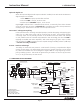
Instruction Manual CONTENTS CONTENTS 1. INTRODUCTION – 4 1.1 LOGICAL CONTROL BLOCKS — 4 1.2 PATENTED TECHNOLOGY — 4 1.3 SIGNAL & CONTROL — 4 1.4 SIMPLIFIED BLOCK DIAGRAM — 5 2. QUICK START – 6 2.1 FRONT PANEL — 6 2.2 REAR PANEL — 7 2.3 GETTING UP & RUNNING — 8 3.3 REAR PANEL VIEW — 10 3. INSTALLATION – 10 3.1 UNPACKING AND INSPECTING — 10 3.2 MOUNTING — 10 3.3 REAR PANEL VIEW — 10 3.4 POWER CONNECTION — 10 3.5 MICROPHONE INPUT — 11 3.6 OUTPUT CONNECTORS — 11 3.7 INPUT TRANSFORMER MODE — 12 3.
MICROPHONE PREAMPLIFIER 1. INTRODUCTION The Aphex Model 1788A is a premium 8-channel remote controlled microphone preamplifier with sophisticated features. Remote control means the preamps can be located anywhere they are needed for optimum performance.
Instruction Manual 1. INTRODUCTION Optional Digital I/O When the optional digital audio output module is installed, three 8-channel simultaneous digital outputs are available: 1. Alesis ADAT® Output, Optical Fiber Interface 2. Tascam® TDIF™ Output, 25 Pin D-SUB 3. Aphex specific AES/EBU Output, 15 Pin D-Sub Digital sync is derived from a selectable internal clock, or externally from either the BNC clock I/O or the TDIF connector.
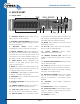
MICROPHONE PREAMPLIFIER 2. QUICK START 2.1 FRONT PANEL 2 5,6,7,8 9,10,11 4 3 1 1. CHANNEL SELECT buttons select one of eight channels for local control. 2. CHANNEL STATUS READOUT displays input gain and maximum output settings; function status and headroom. 12,13,14,15 16 18,19 17 20 21 23 22 24 so that MIDI Channel and Device numbers and Net numbers can be adjusted. After adjustment the STORE saves the selected numbers. 13. MODE selects whether the remote control will be MIDI or LAN. 3.
Instruction Manual 2. QUICK START 2.2 REAR PANEL 2 IN MIDI OUT THRU 4 5 6 RS-232 UTIL AES/EBU OUTPUT 1 2 3 4 10 AUX OUTPUT 11 CH 8 MIC IN CH 7 MIC IN CH 6 MIC IN CH 5 MIC IN CH 4 MIC IN CH 3 MIC IN CH 2 MIC IN CH 1 MIC IN LINE OUT LINE OUT LINE OUT LINE OUT LINE OUT LINE OUT LINE OUT LINE OUT ON ADAT WORD IN CLOCK OUT 90-260 V~50/60Hz 60 WATTS LAN OPTICAL TDIF MODEL 1788A - 8 Channel Mic Pre Aphex Systems Sun Valley, CA 1 3 7 8 9 Optional Digital Module 12 1.
MICROPHONE PREAMPLIFIER 2.3 GETTING UP & RUNNING Here’s a step by step instruction on using the 1788A. Please plug a microphone into Channel 1 and connect the CH1 Main Output to a mixer or recorder input. Turn all units on. 1. Press the LOCAL CONTROL button in the Control Block to enable the front panel controls. It’s a good idea to get into the habit of tapping the LOCAL CONTROL button every time you need to make new adjustments at the front panel just to make sure you have access. 2.
Instruction Manual 2. QUICK START to your equipment and that our MIcLim protection will indeed protect you from clipping your gear. If you don’t know the MIL of your input, then use your mixer or recorder’s meters to indicate full scale input. Simply adjust the 1788A’s Main Output Gain to get just under a full scale reading. When done, tap the TONE button to kill it. NOTE: If completely in doubt, simply set the output level to a number that is 20dB above your 0dB reference level. If +4dBu, set it to +24.
MICROPHONE PREAMPLIFIER 3. INSTALLATION 3.1 UNPACKING AND INSPECTING Your Aphex product was carefully inspected and packaged at the factory prior to shipment. The carton and packing materials are designed to protect the unit during shipment, but you should inspect the carton and its contents for signs of physical damage before use. It is your responsibility to file a damage claim with the shipper.
Instruction Manual 3. INSTALLATION Ground Loops Ground loops hardly ever cause problems within the 1788A since it was designed with high immunity. However, other equipment connected to the 1788A may experience hum and noise from a ground loop. Ground loops can occur when various interconnected equipment is powered from separate AC circuits that are fed from opposite phases of the power feeder. Most service panels assign odd numbered breakers to one phase and even to the other.
MICROPHONE PREAMPLIFIER This connector pinout matches the Tascam Analog DB-25 connector that has also been adopted by many other manufacturers such as Mackie and Yamaha. Ready made cables can be purchased to connect with other products, or to obtain a break-out to XLR plugs. Refer to Sections 5 for more information about using the Main and Aux Outputs. CHANGING THE MODE Remove the 1788A’s top cover and locate the set of jumper pins JP1 and JP2 near each transformer.
Instruction Manual 3. INSTALLATION 3.9 COM PORT This is a standard RS-232 Com Port that runs at a fixed 9600 Baud. It is provided to allow downloading of new firmware into the 1788A. It has no other purpose. Read ahead for instructions on this procedure. 3.10 INSTALLING NEW FIRMWARE INTO THE 1788A Aphex is always striving to improve the performance of its equipment. The firmware that was programmed into your unit was the latest available at the time it was shipped.
MICROPHONE PREAMPLIFIER Mic Input Aux Output Attenuation Output Stage PRE POST 0 to -27dB 1 dB stops +6dB Selectable 26dB Pad Input Stage Digitally Controlled Amplifier Main Output Attenuation Output Stage 0 or -26dB +20dB 0 to +39dB 1 dB stops 0 to -27dB 1 dB stops +6dB AUX Output Main Output EXAMPLE OF USING PRE MODE The FOH position has control over the 1788A’s but the monitor position doesn’t want to be affected by the FOH’s gain changes.
Instruction Manual 4. FUNCTIONS IN DETAIL 4. FUNCTIONS in DETAIL 4.1 LOCAL BLOCK Channel Select and Channel Status Readout Select LOCAL CONTROL and use the CHANNEL SELECT buttons to choose one of eight channels. Only one channel can be selected at a time, unless the MULTIPLE SELECT button is engaged, making it possible to create a group of channels. Each channel has its own Channel Status Readout.
MICROPHONE PREAMPLIFIER NOTE: The gain does not move in 1dB steps. It ramps in small increments (1/4dB steps) between 1dB “stops” to eliminate all gain adjustment glitches. This brings us to making a comment about gain steps. While there are several remote controlled preamps on the market, the problem is that they have stepped gain control and the step size can be as large as 10dB. Even a 3dB step, up or down, in a microphone preamp will cause an audible click or pop when it is changed.
Instruction Manual 4. FUNCTIONS IN DETAIL channels is muted. The channel or channels that have been muted will flash double dash marks in the Gain display of the individual channel status readout to indicate their muted status. The flashing dash marks will alternate with the current gain setting. All parameters may be adjusted while a channel is muted.
MICROPHONE PREAMPLIFIER Enable Limiter Enabling the LIMITER engages the proprietary Microphone Output Limiter (MicLim™) which virtually eliminates the possibility of input overload. The MicLim provides up to 20dB of additional headroom. When the MicLim is inserted into a selected channel, the corresponding LIM ON LED indicator will illuminate on that channel’s status readout as well as the ENABLE LIMITER button. In the event the input exceeds the limiter threshold, the CLIP/LIM indicator will illuminate.
Instruction Manual 4. FUNCTIONS IN DETAIL Once the Adjust/Store button is lighted, you are committed to a new store. You can use the ADJUST dial to change the displayed number to what is wanted. Pressing the Adjust/ Store button again commits the displayed number into effect. The button will then go dark telling you the adjust and store sequence is completed and no further changes can be made without re-starting the sequence.
MICROPHONE PREAMPLIFIER Local Control The LOCAL button allows front panel control. Press it once, you’re in local. Press it again, you’re back in remote. The LOCAL button is lighted when the 1788A is in the local state and dark in the remote state. NOTE: None of the front panel buttons will be lighted while the 1788A is in the remote control state. While in local control state, all remote control is rejected.
Instruction Manual 4. FUNCTIONS IN DETAIL Sample Rate The RATE button toggles through the three available sample rates of 32, 44.1, 48, or 96KHz when running the 1788A on internal clock only. 4.4 MONITOR BLOCK Channel Select Repeatedly pressing the CHANNEL SELECT button toggles through all eight channels which will be displayed in the General Status Readout. The audio of the displayed channel is sent to the headphone jack. It is only possible to monitor one channel at a time.
MICROPHONE PREAMPLIFIER typically is where you want to set your 0VU reference, or average operating level of all following equipment. The Gain indicators in the individual channel status readout are used to show when the channel is in a test tone mode with a blinking bar. When the test tone is activated, it is not possible to adjust the input gain on the channel being tested. Also, the MicLim™ and 26dB PAD functions are defeated. Starting and Stopping the Test Tone 1. Put the 1788A in Local Control. 2.
Instruction Manual 5. USING THE DIGITAL MODULE 5. USING THE DIGITAL MODULE When you have the 1788A’s digital audio option installed, you have a very versatile digital front end for any digital recorder, mixer, or DAW. The mic preamp and A/D Converters are perfectly matched for headroom and low noise. There are only two areas you need to deal with in using the digital module: 1. Synchronization (internal or external) 2. Sending digital audio data to other equipment 5.
MICROPHONE PREAMPLIFIER BNC Clock I/O The sync capability is made even more flexible by providing a feed-through port. When in external sync mode, the BNC output jack is tied directly to the BNC input jack. This allows the sync signal to pass through and be sent on to another unit. Depending on the quality of the driver, up to eight 1788A’s may be looped together from a single clock source.
Instruction Manual 5.
MICROPHONE PREAMPLIFIER Parallel Remote Clocking To Additional 1788A’s or Other Gear Clock D.A.
Instruction Manual 5. USING THE DIGITAL MODULE BRIEF TUTORIAL BRUTE FORCE AND IMPEDANCE MATCHED TRANSMISSION BACKGROUND Synchronization of digital audio equipment shouldn’t be a problem but it is. All the problems would disappear if impedance matched transmission were used by every piece of gear. But, this just isn’t the case, even though it is simple and cheap. “Brute Force” transmission (the kind that causes trouble) is still found throughout the industry.
MICROPHONE PREAMPLIFIER 5.2 SENDING DIGITAL AUDIO The digital module provides three simultaneous 8-channel outputs: 1. Four AES/EBU 110 ohm pairs on a 15-pin D-Sub 2. ADAT® Optical on a TOSLINK Jack 3. Tascam TDIF® on a 25-pin D-Sub Connect your digital audio receivers to any or all of these outputs. You need to take into account the clocking requirements of all outboard equipment. In some special cases this may prevent you from usinng all the outputs at once.
Instruction Manual 6. TYPICAL OPERATION 6. TYPICAL OPERATION This section suggest ways to get the most out of your Model 1788A. Let these ideas serve as inspiration more than instruction. The 1788A is flexible enough to fill many requirements we have not illustrated and probably haven’t even thought of. 6.
MICROPHONE PREAMPLIFIER NOTE: You may run into issues of balanced and unbalanced inserts. The 1788A can drive both types just as easily. You can refer to this manual’s appendix on proper wiring to get information on how to match the 1788A’s Main and Aux Outputs to balanced and unbalanced inputs (there is a difference between Main and Aux unbalanced wiring).
Instruction Manual 6. TYPICAL OPERATION optional digital module, you can use the AES/EBU DB-15 digital output, the DB-25 TDIF (Tascam type) or the ADAT optical output to route all eight channels directly to the digital inputs of a digital recorder or console. Refer to the illustration in Section 5.4 (Using All Outputs to Feed Five Destination Devices) for details on using all available outputs simultaneously. Also, see Section 5.
MICROPHONE PREAMPLIFIER 6.4 USING THE MICROPHONE OUTPUT LIMITER Microphone limiters traditionally consist of a mic preamp followed by a limiter circuit. Until MicLim was devised, that was the only practical way to do it. Everybody is familiar with the clipped overload that’s heard when a performer suddenly gets on the mic too loudly. The compressor/limiter held down the P. A. level, but the preamp was clipping horribly.
Instruction Manual 6. TYPICAL OPERATION Changing the polarity of one or more mics will often clear up the problem. It is always worth the time to experiment with mic polarity. 6.6 GROUPING CHANNELS It is possible to create a group of channels, and treat them all together with any or all of the preamp control functions. Grouping Caveats Several properties of group operation are important to know as they may affect the way you use grouping. 1.
MICROPHONE PREAMPLIFIER 7. Warranty & Service 7.1 Limited Warranty PERIOD One year from date of purchase SCOPE All defects in workmanship and materials. The following are not covered: a. Voltage conversions b. Units on which the serial number has been defaced, modified, or removed c. Damage or deterioration: 1. Resulting from installation and/or removal of the unit. 2.
Instruction Manual 8. SPECIFICATIONS 8. Specifications 8.1 GENERAL SPECIFICATIONS MIC INPUT Connector: Type: Input Z: Maximum Input Level (MIL): CMRR: Nominal Preamp Gain: Phantom Power: Pad: EIN: Tube Type: XLR-3F Jensen Transformer Coupled 1.6KΩ nominal +27dBu (with input pad) 99dB @60Hz, -72dB @ 10KHz 26 to 65dB +48VDC 26dB -124dBu (Input Shorted) ANALOG OUTPUTS Connector: Type: Output Z Balanced: Output Z Unbalanced: Nominal Level Maximum Output Level (MOL): Main Out: 8 ea.
MICROPHONE PREAMPLIFIER 8.2 ARCHITECT’S SPECIFICATIONS Basic Description A multichannel microphone preamplifier comprising eight identical channels that are both locally controllable and remotely controllable by MIDI protocols through MIDI and Ethernet ports. The multichannel preamp shall further comprise an optional digital audio output module. The microphone preamps shall comprise the following selectable functions: 1.) +48VDC Phantom Power; 2.) Polarity Reversal; 3.) 26dB Pad; 4.
Instruction Manual APPENDIX A Appendix A: Balanced and Unbalanced Lines and Operating Levels Interfacing all types of equipment with balanced and unbalanced lines and can sometimes be troublesome. First you have to somehow connect balanced to unbalanced and then you have to deal with different levels. This tutorial will teach you about the principles of balanced and unbalanced lines, wiring standards, and how to effectively interface them.
MICROPHONE PREAMPLIFIER 1 illustrates how the hum is induced into both wires equally and therefore is cancelled out. Since the balanced line has wires that are twisted together, each wire tends to pick up the same amount of induction from external sources. Induction will create no significant voltage difference between the wires, hence the noise (or hum) will not be picked up by the differential input stage.
Instruction Manual APPENDIX B & C lem of a ground loop. First is to eliminate it from its source, and the second is to re-route it through another path. The third is to balance out your unbalanced audio interfaces. Identify the Sources A good way to identify grounding problems is to use a multimeter to check the ac voltage between the chassis of your various gear when no audio cables are hooked up and all gear is plugged in and switched on.
MICROPHONE PREAMPLIFIER CONNECTOR WIRING STANDARDS The 3 pin XLR, 1/4” (63.5 mm) TS mono phone and the 1/4” (63.5 mm) TRS stereo phone are the most commonly used line level connectors in pro audio. Less common is the use of the “RCA” phono jack, which is essentially a consumer type connector. The XLR and the TRS are three conductor and are used for balanced connections. The TS and the RCA are two conductor and are used for unbalanced connections.
Instruction Manual APPENDIX D TABLE 1 - BALANCED & UNBALANCED CONNECTOR WIRING STAN3-Pin XLR 1/4” TRS Phone Standard Wiring Convention (Balanced) Pin-1 Sleeve Ground/Shield (Earth, Screen) Pin-2 Tip Positive (Signal, High, Hot) Pin-3 Ring Negative (Signal Reference, Return, Low, Common) 1/4” TS Phone RCA Standard Wiring Convention (Unbalanced) Tip Center Pin Positive (Signal) Sleeve Shell Ground/Shield (Signal Reference/Return) A word on impedance and interfacing adapters: If you are
MICROPHONE PREAMPLIFIER XLR to XLR OK for Microphones Standard store-bought cable. Shield grounded at both ends. Positives: Good for microphones. Negatives: May cause ground loops through the shield grounds if used to connect equipment together. Preferred for Line Levels Shield grounded at receiving end only. Positives: Stops ground loops and reduces noise. Negatives: None PART 1: BALANCED OUT to BALANCED IN 1/4” TRS Phone to 1/4” TRS Phone Balanced Cables OK Standard store-bought cable.
Instruction Manual APPENDIX D PART 2: BALANCED OUT to UNBALANCED IN Voltage Balanced Outputs It was mentioned that there are several types of balanced output stages in use today. The following diagrams show you how to properly unbalance each type of output. If you follow these instructions, you should have no problems. SIMPLIFIED SCHEMATIC Unbalancing loses half the output level. You lose 6dB of gain.
MICROPHONE PREAMPLIFIER PART 3: UNBALANCED to UNBALANCED Standard Cable (Guitar Cord) Mono (TS) Phone Plug Mono (TS) Phone Plug PART 4: UNBALANCED OUT to BALANCED IN Standard Method Mono (TS) Phone Plug Enhanced Method (Pseudo Balanced) Advantage: Reduced Hum and Noise Pickup Stereo (TRS) Phone Plug (Guitar cord of Part 3 above usualy works just as well) Mono (TS) Phone Plug Stereo (TRS) Phone Plug Not Used Male XLR Male XLR Mono (TS) Phone Plug Mono (TS) Phone Plug Not Used PART 5: “Y” INSERT C
Instruction Manual APPENDIX E APPENDIX E: HELPFUL WIRING TABLE Also see next page...
MICROPHONE PREAMPLIFIER NOTES The following notes are referenced in the text and in Table 2 on the preceding pages. Note 1: ADDITIONAL READING SUGGESTIONS: Sound System Engineering by Don Davis and Carolynn Davis (Howard W. Sams and Co.), Handbook for Sound Engineers (The New Audio Cyclopedia) Edited by Glen Ballou (Howard W. Sams and Co.) and Sound Reinforcement Handbook by Gary Davis and Ralph Jones (Hal Leonard Publishing Corp.).
Instruction Manual APPENDIX F APPENDIX F: WORD CLOCK CABLING useful bandwidth of the line is maximized under these con- Transmission Systems ditions, and the pulse waveform is best preserved. There are basically two systems in use for distributing word clock by coaxial lines: 75Ω matched, and unmatched with unspecified impedance. We sometimes call the unmatched method “brute force”. You’ll see why as you go through That is not to say the pulse waveform won’t undergo some degradation.
MICROPHONE PREAMPLIFIER not terminated in its characteristic impedance. In most cas- Though ugly from an engineering viewpoint, the only solu- es, unmatched word clock lines are driven by a low output tion is such cases is to apply unmatched transmission lines impedance voltage driver and loaded by a high impedance as best as one can and then rely on “brute force” clocking receiver. to hold it all together.
Instruction Manual APPENDIX F Figure 5 End-of-Line Termination the last unit in line, the best option for terminating the line as shown in figure 5. Last Unit In Line Clocking The 1788A With Brute Force Not knowing what the 1788A’s word clock input may be UTIL driven by, we made it automatically accept the brute force AES/EBU OUTPUT 1 2 3 4 voltage levels. ON When accepting brute force clock, do not install ADAT WORD IN CLOCK OUT a termination adapter - it would be of no benefit.
MICROPHONE PREAMPLIFIER This product is protected under one or more of the following Aphex patents.