
Owner manual


Page 10
MICROPHONE PREAMPLIFIER
Page 11
Instruction Manual
3. INSTALLATION
Ground Loops
Ground loops hardly ever cause problems within the 1788A since it was designed with
high immunity. However, other equipment connected to the 1788A may experience hum
and noise from a ground loop. Ground loops can occur when various interconnected
equipment is powered from separate AC circuits that are fed from opposite phases of the
power feeder. Most service panels assign odd numbered breakers to one phase and even
to the other. Rooms that are powered from more than one circuit can have outlets that are
out of phase. Adjacent rooms may be powered with opposite phase.
NOTE: If your system is plagued with ground loop troubles, you should try to get all
the equipment onto the same phase or use a local power isolation transformer.
3.5 MICROPHONE INPUT
The eight transformer coupled microphone INPUT CONNECTORS are locking female 3-pin
XLR’s wired with pin 2 positive.
3.6 OUTPUT CONNECTORS
Two separate analog outputs per channel are provided:
1. Transformerless servo-balanced Main Outputs on eight separate XLR’s
2. Eight transformerless active balanced Aux Outputs on a single DB-25 connector.
Main and Aux outputs have separate individual output level control. Using these two
outputs, the 1788A can serve as an active mic splitter.
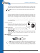
Pin connections for the XLR type connectors follow the international standard of pin-1
ground, pin-2 positive and pin-3 negative as shown below.
MALE AND FEMALE 3-PIN XLR CONNECTORS
NOTE: Read more information about audio wiring practices in the appendices.
DB-25 PIN CONFIGURATION (AUX OUTPUT)
The following chart is a pin configuration for the analog DB-25 connector.
1
2
3
3
3
1
2
3
2
2
1
1
2 Positive (+)
3 Negative (-)
1 Shield (Ground)
1
14 15 16 17 18 19 20 21 22 23 24 25
2 3 4 5 6 7 8 9 10 11 12 1
3
13
25 24 23 22 21 20 19 18 17 16 15 14
12 11 10 9 8 7 6 5 4 3 2 1
CH1 CH2 CH3 CH4 CH5 CH6 CH7 CH8
(+) 24 10 21 7 18 4 15 1
(-) 12 23 9 20 6 17 3 14
GND 25 11 22 8 19 5 16 2
Female
Male