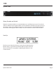
88 Remote Controlled 8 Channel Microphone Preamplifier Instruction Manual P/N 188-3200 Preliminary Rev 1 Released 01/23/09 Manufactured by Aphex 3500 N San Fernando Blvd Burbank, CA 91505 USA Copyright 2009 Aphex. All rights reserved.
188 Safety Declarations CAUTION: For protection against electric shock, do not remove the cover. No user serviceable parts inside. WARNING: This equipment has been tested and found to comply with the limits for a Class A digital device pursuant to Part 15 of the FCC Rules. These limits are designed to provide reasonable protection against harmful interference when the equipment is operated in a commercial environment.
188 Table of Contents 1.Introduction 2.Quick Start Front Panel LCD Display and Rotary Encoder/Switch Front Panel Screens 3. Rear Panel 4. Model 188 block diagram and signal flow 5. Installation 6.
188 Introduction Why remote controlled preamplifiers? Locating the mic preamplifier as close as possible to the microphone eliminates the long cable runs at mic level. Induced noise would be amplified. In addition, capacitance and resistance in that long cable run would fect af the performance of the microphone. Transformer splitters are only effective in isolating ground.
188 Quick Start Rotary Encoder and Switch Rotate the encoder clockwise or counterclockwise to scroll between screens. Press the-en coder to make the cursor appear within a screen. Rotate the encoder to move the cursor to the value or status to be changed and press to select, the cursor will start blinking. Rotate the encoder to change the value or status. Press the encoder to save the value or status. Start Up The first screen shows the firmware version that is loaded into the Model 188.
188 Metering This screen shows a twelve segment peak level meter for each channel. When there is an overload the clip on that channel is indicated with a “!”. When the unit receives a command from a remote controller, “RC” will light for half a second. We recommend that this screen be selected when set up is complete. Channel Status and Input Gain There is one screen for each of the eight channels.
188 System Configure In order to safeguard against unwanted changes to the system configuration, the rotary encoder must be pressed in for several seconds. The system configuration includes clock source, format and sample rate, display contrast, Net Number assign, DHCP/IP select and system configure exit. The first screen after the encoder is held in is Clock Source.
188 Contrast Adjust Press encoder in and then rotate clockwise for more contrast, counter-clockwise for less contrast. Net Number The Net Number identifies the particular unit within a system. Note: There must be only one unit assigned to one Net Number otherwise the Remote Control and metering will be unpredict able. DHCP/FIXED IP DHCP requires a router which will ‘serve’ an IP address dynamically. Fixed IP forces the address that is programmed into the unit and modified by the Net Number.
188 Exit Configure Press the encoder in and the display will change to the metering screen. Rear Panel Microphone Inputs Each microphone input is a locking female XLR (pin #1 ground, pin # 2 ‘+’ and pin # 3 ‘-‘). Maximum input level is +21dBu with Pad engaged and the input gain at 26dB. Line Level Output The channel outputs appear on a 25 pin D-Sub female connector using the Tas cam analog standard pin out. Maximum output level is fixed at +21dBu.
188 SYNC Standard BNC connectors with 75Ω terminations are provided for input (IN) and output (OUT) of word clock. Input may be either word clock or AES. The output will be word clock. The output will be the rate indicated on the front panel. LAN Standard RJ-45 connector for Ethernet remote control as well as for future downloads of firmware. POWER Standard IEC receptacle. The Model 188 has a switch mode power supply which can accept any voltage from 90 to 260VAC and at either 50 or 60Hz.
188 Simplified Block Diagram Signal Flow The microphone signal enters the Model 188 through the female XLR, through a switch for the Pad (-26dB), the mic pre front end including the transformer with 26dB of gain and the low cut filter, polarity reverse, through the variable gain amplifier (0 to 39dB of gain), to the A/D converter and the output stage. Note: if the analog output is in “pre” mode the output gets its signal after the front end but before the variable gain amplifi re.
188 Installation 3.1 UNPACKING AND INSPECTING Your Aphex product was carefully inspected and packaged at the factory prior to shipment. The carton and packing materials are designed to protect the unit during shipment, but you should inspect the carton and its contents for signs of physical damage before use. It is your responsibility to file a damage claim with the shipper. We encourage you to save the original packing materials in case you should ever need to ship this unit out for servicing. 3.
188 Ground loops hardly ever cause problems within the 188 since it was designed with high immunity. However, other equipment connected to the 188 may experience hum and noise from a ground loop. Ground loops can occur when various interconnected equipment is powered from separate AC circuits that are fed from opposite phases of the power feeder. Most service panels assign odd numbered breakers to one phase and even to the other.
188 3.10 INSTALLING NEW FIRMWARE INTO THE 188 Aphex is always striving to improve the performance of its equipment. The firmware that was programmed into your unit was the latest available at the time it was shipped. There may be updates to the firmware that are made from time to time. Please check the Aphex website at www.aphex.com to see if there are any updates made to the firmware from the time you had purchased or last updated the unit.
188 CHANGING THE PRE/POST SETTING Remove the top cover and locate the jumper for each preamp behind the DB-25 connector.. Move the jumper to the appropriate position.
188 4. Functions in Detail Channel Select and Channel Status Readout Use the encoder to select the channel. Only one channel can be selected at a time. E ach channel has i ts own C hannel S tatus R eadout. O n the bottom l ef t i s a two-di gi t gai n readout displaying the input setting. While setting the gain you may want to scroll back to the Meter Screen. The vertical 12 segment meter indicates the available peak headroom measured in dB (4dB increments).
188 much easier and quicker than the alternative of swapping cables and equipment. Low Cut 75Hz To help reduce low frequency rumble that can be caused by wind, handling of the microphone or bad vocal articulation (popping “P’s”), a 75 Hz, 12dB per octave low cut filter is provided. In general, this filter could be engaged when mic’ing vocals as it will not usually affect the tonality of the human voice.
8 7. Warranty & Service 7.1 Limited Warranty PERIOD One year from date of purchase SCOPE All defects in workmanship and materials. The following are not covered: a. Voltage conversions c. Damage or deterioration: 1. Resulting from installation and/or removal of the unit. 2. Resulting from accident, misuse, abuse, neglect, unauthorized product instructions contained in the User’s Manual. 3. Resulting from repair or attempted repair by anyone not authorized by Aphex Systems. 4.