EXCITER® AURAL EXCITER® & OPTICAL BIG BOTTOM® LEGENDARY PROFESSIONAL AUDIO ENHANCEMENT OWNER’S MANUAL
Exciter Safety Declarations CAUTION: For continued protection against risk of fire, replace only with the same type and rating of fuse. ATTENTION: pour une protection continue contre les risques d’incendie, ne remplacer qu’avec la même valeur et même type de fusible. WARNING: Do not place objects containing liquid on this unit as it is not designed to protect against spillage. Do not expose this unit to dripping or splashing of liquids as the unit is not designed to protect against these occurances.
Owner’s Manual ATTENTION This instruction manual is intended to be a complete reference on the Exciter, and we encourage you to read it thoroughly. At the very least, please look over the Table of Contents to familiarize yourself with the scope of information available to you. In order to help you get maximum use and satisfaction from your new Exciter, we have tried our best to anticipate most of the questions and problems users are likely to encounter.
Exciter Table of Contents 1.0 QUICK START 1.1 Unpacking and Inspecting 5 1.2 Simple Setup 5 1.3 Suggested Control Settings 6 2.0 INTRODUCTION 2.1 The Aural Exciter and Big Bottom Technologies Explained 2.2 Simplified Block Diagram 8 9 3.0 INSTALLATION AND INTERFACING 3.1 Installation 10 3.2 Rear Panel View 10 3.3 AC Line Connector 10 3.4 Input Connectors 10 3.5 Output Connections 10 3.6 Operating Level Selector Switch 10 3.
Owner’s Manual 1.0 Quick Start 1.1 UNPACKING AND INSPECTING Your Aphex product was carefully inspected and packaged at the factory prior to shipment. The carton and its internal packing materials are designed to protect the unit from most rough handling than can occur during transport and handling. However, you should thoroughly inspect the carton and its contents for signs of physical damage before attempting to use this device.
Exciter Quick Start 1.3 SUGGESTED CONTROL SETTINGS You are encouraged to experiment with the range of settings printed on the face of the unit. When testing the effect of Big Bottom, turn off the Aural Exciter Mix. Likewise, turn off the Big Bottom AMOUNT when testing the effect of the Aural Exciter. Doing so allows you to isolate each process and more clearly hear the effect.
Owner’s Manual Quick Start In-Line Hookup to Rear Panel From Outputs of Other Line Level Devices to Exciter’s Inputs Use balanced or unbalanced cables as needed. Consult section 7 for wiring options. Select the correct OPERATING LEVEL to match your interconnecting equipment. Both the outputs and inputs are switched simultaneously. AURAL EXCITER FREQUENCY CONTROL Adjusts the frequency range of the effect. Tune lower for more mid pickup and presence. Tune higher for an airier sound.
Exciter 2.0 Introduction 2.1 THE AURAL EXCITER AND BIG BOTTOM TECHNOLOGIES EXPLAINED The AURAL EXCITER is an audio processor that recreates and restores missing harmonics. Harmonics are musically and dynamically related to the original sound, revealing the fine differences between voices and various instruments. Reproduced sound is audibly different than the original live sound because of the loss in harmonic detail, often sounding dull and lifeless.
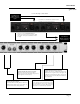
Tune 50Hz-190Hz Tunable Lowpass Filter Tune 800Hz-6kHz Tunable Highpass Filter Mix Variable Drive Phase & Dynamics Processor Mix Variable Harmonics Transient Discriminate Harmonics Generator +4/-10 Operating Level Switch SUM 1/4” TRS XLR-3M Active Balanced Outputs Effects are created through dynamic phase, frequency, and amplitude modification and recombination. Big Bottom Sidechain Aural Exciter Sidechain 1/4” TRS XLR-3F Active Balanced Inputs 2.
Exciter 3.0 Installation & Interfacing 3.1 INSTALLATION The Exciter occupies a single rack space (45mm or 1-3/4 inches) of a standard EIA equipment rack. When rack mounting, use the following recommended hardware: #10-32 x 3/4” Button Head Cap Screws with thick plastic or nylon washers between the screw and the rack. If the rack does not have threaded thru-holes for the screws, then we recommend a #10 Tinnerman Clip Nut. Never restrict air flow through the device’s vents.
Owner’s Manual Installation & Interfacing 3.8 WIRING DIAGRAMS Throughout this manual we use TS and TRS as abbreviations. Here is a complete definition: TS refers to the Tip-Sleeve or “mono” 2-conductor type and TRS refers to Tip-Ring-Sleeve or “stereo” 3 conductor type 1/4” phone connectors. This applies to jacks (female connectors) and plugs (male connectors). Note: Use only conventional 1/4” phone plugs with the Exciter.
Exciter 4.0 Controls & Indicators 4.1 FRONT PANEL VIEW 4.2 BIG BOTTOM FREQUENCY CONTROL This control lets you optimize the bass enhancement frequency band. The Exciter’s controls have typical range settings printed on the front panel. Where this is set depends upon your sound system and the type of music being played. Typically, 12:00 is a universal position. However, you may want to experiment with other settings. The range is from 50Hz to 200Hz. At center, you are tuned to about 80Hz. 4.
Owner’s Manual Controls & Indicators 4.5 AURAL EXCITER FREQUENCY CONTROL The Aural Exciter Frequency control adjusts the corner frequency of the high pass filter, thus setting the range of frequencies being enhanced by the Aural Exciter. The range of the corner frequency is 600Hz (fully counter clockwise) and 5kHz (fully clockwise). The 12 o’clock setting is approximately 3kHz. As the tune control is adjusted clockwise, less and less mid-frequency enhancement will take place.
Exciter 5.0 Operation & Applications 5.1 IN-LINE PATCHES The Exciter has two independent channels. Each channel contains one Big Bottom circuit and one Aural Exciter circuit. Each channel may be used on completely different input signals. When the Exciter is used on a stereo mix, match the settings of the controls on each channel. The Exciter is typically used as an in-line device, see illustration below.
Owner’s Manual Operation & Applications WIRING A TRS INSERT CABLE Tip IN Sleeve (Ground) Tip Exciter Tip (Send) Console Insert Jack Sleeve Sleeve Sleeve Tip Ring Ring (Return) OUT Note: Some manufacturers reverse the Tip and Sleeve connections, where the Tip is Return and the Sleeve is Send. This would mean that IN becomes OUT and OUT becomes IN when referring to the previous drawing. Be sure to check the owner’s manual of your console. 5.
Exciter Operation & Applications 5.3 EFFECTS LOOP PATCHES (cont.) SEPARATING THE AURAL EXCITER & BIG BOTTOM EFFECTS The following illustrates how you can use a mono Big Bottom and a mono Aural Exciter separately on different effects sends. Configuring the Exciter as illustrated provides two independent mono processing channels. Let’s assign Effects (or AUX) Send 1 to the Aural Exciter on channel one and Effects (or AUX) Send 2 to the Big Bottom on channel two.
Owner’s Manual Operation & Applications 5.5 OPTIMIZING BIG BOTTOM EFFECTS There are two independent channels, each containing one Big Bottom circuit. Each channel may be use on completely different signals. Two identical sets of controls are provided. The Drive control needs to be set at a point where the processor receives the optimum level required for Big Bottom to work effectively. The Amount control adjusts the amount of Big Bottom enhancement being added to the unmodified signal.
Exciter Operation & Applications 5.7 LIVE CONCERTS & SOUND REINFORCEMENT The Aural Exciter adds intelligibility without increasing levels, even with speaker systems that have reduced bandwidth. It does this through higher harmonics generation which improves vocal articulation through a sound system.
Owner’s Manual Operation & Applications Another situation is acoustic music performances such as folk or bluegrass. In this instance there is no problem with a high stage level. However, you have instruments that by nature have a low acoustical output that require high amounts of gain to reproduce them through PA and stage monitor systems. In this situation, you’re typically on the edge of feedback especially as the number of mics increase.
Exciter Operation & Applications 5.11 KARAOKE & STEREO SYSTEMS The Exciter is a perfect complement to Karaoke systems. In a small club situation, often the sound system and the microphones have a limited dynamic range and frequency response. Big Bottom will help tighten and increase bass. Aural Exciter helps overdubbed vocals become more intelligible and clearer in the mix. The Exciter can give Karaoke performers that big “recording studio” sound that audiences want to hear.
Owner’s Manual Operation & Applications RELATING THE FREQUENCY RANGES OF THE BIG BOTTOM AND AURAL EXCITER TO THE FUNDAMENTALS AND HARMONICS OF SOUND Big Bottom Range Aural Exciter Range MID MAX MIN MID MAX Audible Harmonics MIN Page 21
Exciter 6.0 Warranty & Service 6.1 Limited Warranty PERIOD One year from date of purchase SCOPE All defects in workmanship and materials. The following are not covered: a. Voltage conversions b. Units on which the serial number has been defaced, modified, or removed c. Damage or deterioration: 1. Resulting from installation and/or removal of the unit. 2. Resulting from accident, misuse, abuse, neglect, unauthorized product modification or failure to follow instructions contained in the User’s Manual. 3.
Owner’s Manual 7.0 Specifications OPERATING LEVEL Switch Setting: INPUT Connector: Type: Balanced: Unbalanced: Nominal Level: Maximum Level: CMRR: +4dBu -10dBV XLR-3F and TRS 1/4” phone jacks Transformerless, active balanced 40KΩ 20KΩ +4dBu +27dBu >40dB Same Same 40KΩ 20KΩ -10dBV (-7.8dBu) +12.5dBV (+14.
Exciter Patent Notice This product is protected under one or more of the following Aphex patents.