
User's Manual

Last Revision: 6/25/2009 Copyright 2009 API Healthcare Corporation.
API Internal Document – Company Confidential Information
Page 3of 4
b. Pull out the center pin on each of the four 3-pin segments. This will leave only the 2 outer pins.
(Save the unused segments for other Prox Boards.)
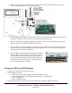
c. Use a modified 3-pin segment and insert the short side of the pins into the bottom 2 holes of the J8
connector, numbers 1 and 2, on the 50 circuit board. Solder them in place.
d. Insert the short side of a single pin segment, into each of the top 2 holes, numbers 4 (CLK) and 5
(DATA) of the 50 circuit board. Solder them into place.
e. Cut a 1½-inch by 1¼-inch rectangle from a sheet of plastic insulation. Stick this insulator onto the
components side of the Prox Board per the diagram. Make sure it covers the ICs and the fuse but
does not cover the LED or the pin holes.
f. Insert the HID Prox Board pins into the J8 holes making
sure the LED will fit into the hole in the TA-50 circuit
board. Solder it in place so that it is parallel with the TA-
50 circuit board and with the plastic insulator tight to the
on the foil side of the circuit board. Cut the protruding
pins without damaging the antenna.
Testing the HID Prox RFID Module
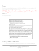
1. Apply power and wait for the unit to boot up.
2. Enter Diagnostic Mode:
a. Hold the F1 key until the display shows: DIAGNOSTIC PIN
b. Enter the PIN number by pressing the following keys: 415049<ENT>
c. Press 1 (BADGE)
d. Press 1 (RAW DATA)
3. Hold the test badge near the front plate of the reader until it displays: PROX SUCCESS.