
User's Manual

Last Revision: 6/9/2009 Copyright 2009 API Healthcare Corporation.
API Internal Document – Company Confidential Information
Page 4of 5
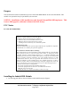
Figure 3.
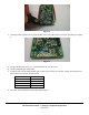
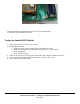
7. Place the assembly in the case as shown in Figure 4.
Figure 4.
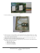
8. Remove the paper covering the adhesive on the stand offs. Place the TA-500 board in the case. Align
the TA-500 board so the mounting holes line up with the 3 case mounting bosses. Press gently to make
contact with the Indala board stand offs.
9. Remove the TA-500 circuit board. The Indala should be mounted on the board. Press firmly on the
Indala board to ensure good adhesion between the two boards.
10. Per Figure 5, trim the wires to the proper length and strip off 1/8” from the free ends. Solder the wires
from Indala cable harness as follows:
a. Red wire to J8-1 (+5V)
b. Black wire to J8-2 (GND)
c. Yellow wire to J8-4 (CLK)
d. Green wire to J8-5 (DATA)