
User manual
APC-3228A User Manual
28
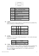
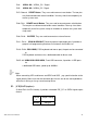
35. CPU SCREW HOLES:
CPU FAN SCREW HOLES, Four screw holes for fixed CPU Cooler assemble.
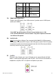
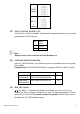
36. H5/H6:
MPCIE1 SCREW HOLES, H5 for mini PCIE card (30mmx30mm) assemble. H6 for mini PCIE
card (30mmx50.95mm) assemble.
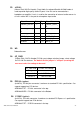
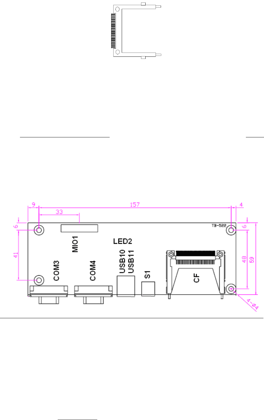
37. TB-522:
ASB-M801 I/O Card, via a dedicated cable connected to ASB-M801 MIO1.
LED2:
CF Card LED status.
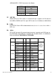
S1:
PWR BT: POWER on/off Button, They are used to connect power switch button. The
two pins are disconnected under normal condition. You may short them temporarily to
realize system startup & shutdown or awaken the system from sleep state.
PWR LED: POWER LED status.
COM3: