
User manual


ARCHMI-7XX User Manual
24
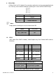
JP1 Pin#
Function
Close 1-2
COM1 RI (Ring Indicator) (default)
Close 3-4
COM1 Pin9:DC+5V (option)
Close 5-6
COM1 Pin9:DC+12V (option)
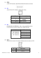
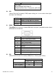
17. S_232:
(Switch),COM1 jumper setting, it provides selectable RS232 or RS422 or RS485 serial
signal output.
Function
S_232 Pin#
RS232
(Default)
ON:
Pin1, Pin2, Pin3, Pin4
RS422
(option)
OFF:
Pin1, Pin2, Pin3, Pin4
RS485
(option)
OFF:
Pin1, Pin2, Pin3, Pin4
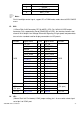
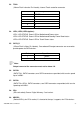
18. S_422:
(Switch),COM1 setting, it provides selectable RS232 or RS422 or RS485 serial signal
output.
Function
S_422 Pin#
RS232
(Default)
OFF:
Pin1, Pin2, Pin3, Pin4
RS422
(option)
ON:
Pin1, Pin2, Pin3, Pin4
RS485
(option)
ON:
Pin1, Pin2, Pin3, Pin4
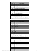
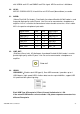
S-422
Mode
Pin11-12(Off)
ATX Power
Pin11-12(On)
Auto Power on (Default)
19. COM1:
(Type DB9),Rear serial port, standard DB9 Male serial port is provided to make a direct
connection to serial devices. COM1 port is controlled by pins No.1~6 of JP1,select
output Signal RI or 5V or 12V, For details, please refer to description of JP1 and S_232
and S_422 setting.