
User manual


ARCHMI-7XX User Manual
29
34. LAN1/LAN2:
LAN1/LAN2: (RJ45 Connector), Rear LAN port, Two standard 10/100/1000M RJ-45
Ethernet ports are provided. Used intel 82574L chipset, LINK LED (green) and ACTIVE
LED (yellow) respectively located at the left-hand and right-hand side of the Ethernet
port indicate the activity and transmission state of LAN.
35. BUZ1:
Onboard buzzer.
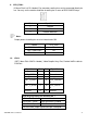
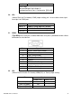
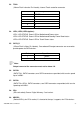
36. CN2:
(DF13-30P Connector),For expand output connector, It provides eight GPIO,one RS422
or RS485,one USB2.0,one Power on/off, one Reset.
Function
Signal Name
Pin#
Signal Name
Function
5V
5V_S5
2
1
5V_S5
5V
SIO_GPIO61
GPIO_IN2
4
3
GPIO_IN1
SIO_GPIO60
SIO_GPIO63
GPIO_IN4
6
5
GPIO_IN3
SIO_GPIO62
SIO_GPIO21
GPIO_OUT2
8
7
GPIO_OUT1
SIO_GPIO20
SIO_GPIO23
GPIO_OUT4
10
9
GPIO_OUT3
SIO_GPIO22
Ground
12
11
Ground
485 or 422
485+_422TX+
14
13
485-_422TX-
485 or 422
RS422
422_RX+
16
15
422_RX-
RS422
NC
18
17
NC
NC
20
19
NC
5V
5V_S0
22
21
HDD_LED+
HDD LED
USB2.0
5V_USB01
24
23
5V_USB01
USB2.0
USB1_P
26
25
USB1_N
Ground
28
27
FP_RST-
RESET
Power auto on
PWRBTN_ON
30
29
Ground
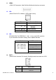
COM3 BIOS Setup:
Advanced/W83627UHG Super IO Configuration/Serial Port 3 Configuration
【RS-422】
Advanced/W83627UHG Super IO Configuration/Serial Port 3 Configuration
【RS-485】
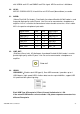
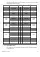
37. CN3:
(1.27mm Pitch 2X30 Pin Header), For expand output connector, It provides four GPIO,