AD-8000 24-bit 8-channel Digital Audio Conversion System Operating Manual and UV22® License Agreement Rev 1.5 — June 1999 Firmware revision 1.
AD-8000 Operating Manual Manual written by Bob Clearmountain and Brent Elder. Edited by Julio Alvarez and Joe Raia. Interconnection diagrams by Julio Alvarez. Produced and edited by Richard Elen. Color by WaterColor. At a theater or drive-in near you. Batteries not included. SoftLimit and UV22 are Registered Trademarks of Apogee Electronics Corporation. All other trademarks are property of their respective holders.
AD-8000 Operating Manual The Apogee AD-8000 24-bit, 8-channel Digital Conversion System It’s not an option—it’s a necessity!
AD-8000 Operating Manual Registration and Warranty Information Be sure to register your AD-8000, either by filling in the enclosed Registration Card or by completing our on-line registration form at our Web site: http://www.apogeedigital.com/register.html. If you do so, Apogee can contact you with any update information. As enhancements and upgrades are developed, you will be contacted at the registration address. Firmware updates are free for the first year of ownership.
AD-8000 Operating Manual Declarations of Conformity Declaration of Conformity—FCC Apogee AD-8000 This device complies with Part 15 of the FCC Rules. Operation is subject to the following two conditions: (1) This device may not cause harmful interference, and (2) This device must accept any interference received, including interference that may cause undesired operation. This equipment has been tested and found to comply with the limits of a Class B digital device, pursuant to Part 15 of the FCC Rules.
AD-8000 Operating Manual Licensing and Legal Information Carefully read the following legal agreement prior to using the UV22 process provided in the AD-8000. Use of UV22 constitutes your acceptance of these terms. If you do not agree to the terms of the agreement, promptly return the AD-8000 and the accompanying items, including written materials and containers to the location where you obtained them for a full refund. 1.
AD-8000 Operating Manual Table of Contents Registration and Warranty Information Service Information Declarations of Conformity Licensing and Legal Information Owner’s Record Warnings ...........................................................................................................................9 Environmental Warnings ...................................................................................................................................9 Power Warning................................
AD-8000 Operating Manual Source Switch..................................................................................................................................................18 Rear Panel .......................................................................................................................19 Analog Inputs..................................................................................................................20 The Analog Front End ........................................
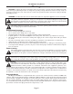
AD-8000 Operating Manual Warnings CAUTION: To reduce the risk of electrical shock, do not remove the cover. No user serviceable parts inside; refer servicing to qualified personnel. To change the operating voltage and install certain accessory cards, it is necessary to remove the cover of the unit. As a result, such operations must be carried out only by technicallyqualified personnel. WARNING: To reduce the risk of fire or electrical shock, do not expose this appliance to rain or moisture.
AD-8000 Operating Manual Introduction The AD-8000 is an eight-channel 24-bit A/D converter with extensive I/O and processing features and an extensive, accessible user interface. Its primary components are the A/D section and its associated analog electronics, an extensive digital I/O section with four stereo AES/EBU outputs, plus one stereo AES and one stereo S/PDIF input as standard.
AD-8000 Operating Manual Getting Started Installation The AD-8000 incorporates a highly-specified and rated power-supply section. However, when fully loaded with interface and D/A cards, the unit does consumer quite a lot of power, and thus generates a certain amount of heat. As a result, we recommend that, to minimize the risk of failure, you insure that the AD-8000 is installed in a well-ventilated environment, with plenty of airflow around the unit.
AD-8000 Operating Manual If you have the optional Video Sync module installed, the AD-8000 gains the ability to lock to PAL, NTSC or Monochrome (B&W) external video sync, chosen by selecting VIDEO. The connected video sync is automatically detected, locked to and the sync rate is displayed. The unit also gains the ability to do “Pull-Ups” and “Pull-Downs” — multiplying or dividing the NTSC video sync rate by 1.001 to compensate for the speed change necessary for film to video (or vice versa) transfers.
AD-8000 Operating Manual Soft Limit Soft Limit® is the same exclusive transparent system of controlling digital “overs” that Apogee has become famous for with our two-channel AD-500 and AD-1000 A/D Converters. It can allow several more decibels of apparent level to be recorded on your digital tape, while subtlely giving your recording a more “analog” sound. Soft Limit may only be selected on analog inputs and cannot be selected on digital input sources.
AD-8000 Operating Manual Example: Let’s say you have a DA-88 tape you would like to transfer into Pro Tools, but to save time you want to try a guitar part on track 8 while it’s going. 1. Bus the guitar channel on your console to analog input 8 on the AD-8000. 2. Select your digital source with the SOURCE button – e.g. if the DA-88 is connected to an AMBus card that is in slot “A”, select AMBUS A. 3. Press the DIGITAL IN button, then press CHANNEL SELECT buttons 1 through 6.
AD-8000 Operating Manual Monitor The AD-8000 incorporates a high-quality, 18-bit stereo digital to analog converter for monitoring purposes. Briefly pressing the MONITOR SELECT button routes program from the selected pair of channels or the AES input to three destinations: the S/PDIF output on the back of the unit, the D/A converter for the front panel headphone output, and the optional 24-bit stereo D/A card (if installed). There is no facility for mixing tracks together.
AD-8000 Operating Manual AES 8 AMBus Card The AD-8000 comes equipped with a single XLR female socket for a 2-channel AES/EBU input. The AES AMBus card provides an additional eight channels of AES/EBU I/O capability. This card also incorporates bitsplitting, like the ADAT and TDIF cards, to allow six channels of 20-bit or four channels of 24-bit audio to be recorded on a 16-bit 8-channel system.
AD-8000 Operating Manual Once a sync source is selected, the processor measures the sample rate and sets the sample rate LEDs appropriately. The measurement is accurate to one part in 2000, so that a “pulled” rate can be distinguished accurately. For example, 47.952 kHz can be distinguished from 48 kHz. The processor disables invalid sync selections—selecting 44.1 when the external sync source is at 48 is not allowed, for example.
AD-8000 Operating Manual At power-up, the microprocessor will recall the last selected sync source and determine if it is active (via the measurement circuitry.) If it is active, then the AD-8000 will lock to it, preferably at the old sample rate, or if that is not possible, at the present sample rate. If it is not active, then the microprocessor will default to CRYSTAL at 48 kHz.
AD-8000 Operating Manual button is used to select S/PDIF as SOURCE. Likewise when the S/PDIF SYNC SOURCE LED is lit while the AES/EBU SYNC SOURCE LED is blinking then AES/EBU may be selected as SYNC SOURCE if the SOURCE button is used to select AES/EBU as SOURCE. Blinking SOURCE LED When a SOURCE LED is lit while another is blinking then the blinking SOURCE LED may be selected as Source if the SYNC SOURCE button is used to select an appropriate SYNC SOURCE.
AD-8000 Operating Manual AES and S/PDIF Input Connectors: Female XLR connector (AES), RCA connector (S/PDIF)—each carries two channels Function: Multiplexed AES or S/PDIF receiver S/PDIF Output Connector: RCA connector—carries two channels Function: S/PDIF transmitter Word Clock/Video In Connector: BNC connector Function: Word clock sync in or Video (PAL, NTSC, Mono) in Word Clock Out Connector: BNC connector Function: Word clock sync out Analog Expansion Card Connectors: Plug-in edge connector on 0.
AD-8000 Operating Manual Headroom requirements vary with the type of music, but can range from 8 dB for rock, to 24 dB for classical music. The first amplifier stage can accommodate this range with no compromise in the noise floor due to careful design. To further optimize the design, the attenuator has two settings, one for professional inputs and one for consumer inputs. Common Mode Rejection/RF Filtering The first stage includes a common-mode and differential filter.
AD-8000 Operating Manual Four AMBus slots on the AD-8000 allow up to eight channels of digital input, in virtually any format. The onboard microprocessor senses the identity of any AMBus card which is plugged in, and will enable the card to be selected on the front panel as an input. It will also allow the card to receive the eight digital output channels (if permitted by the specific card).
AD-8000 Operating Manual Eight-Channel D/A (Optional) The optional 8-channel D/A card contains four 24-bit stereo DACs with filtering, digital de-emphasis (including de-emphasis override for digital signals with an incorrectly-set emphasis flag), DC removal, automatic soft mute and gain adjustment circuitry. The same output channels going to the AES/EBU output jacks are also routed to the 8-channel D/A card. In the case of both D/A cards, output levels can be switched between +4 dBu and -10 dBV.
AD-8000 Operating Manual SW10 Autosync ENABLED Autosync DISABLED Over Detection Threshold The over detection threshold is the number of consecutive full-scale samples that constitutes a digital “over”. The Over indicator will increment when the threshold is reached. To avoid rapid saturation of the counter, the DSP “times out” for one second after detecting an over, before detection is re-enabled.
AD-8000 Operating Manual UV22HR will be fitted to new AD-8000 units, and will be available as an upgrade to most AD-8000s. For availability information, check our Web site at http://www.apogeedigital.com/ UV22 Process Caveats UV22 Encoding is intended to be applied at the final step in the signal chain before the actual mastering device.
AD-8000 Operating Manual ADATs AD-8000 Digital Master AMBus ADAT8 OPTICAL AMBus ADAT8 OPTICAL AMBus ADAT8 OPTICAL ADAT 1 slave to AD-8000 WC via optical ADAT Sync ADAT 2 slave to BRC ADAT sync ADAT Sync ADAT 3 slave to BRC ADAT sync ADATs w/ BRC AD-8000 Digital Master AMBus ADAT8 AMBus OPTICAL ADAT8 OPTICAL slave AMBus ADAT8 OPTICAL WORD CLOCK to 48K INPUT ADAT 1 ADAT Sync to BRC/ADAT sync ADAT Sync ADAT 2 Alesis BRC slave to BRC/ADAT sync ADAT Sync ADAT 3 slave to BRC/ADAT sync Page 26
AD-8000 Operating Manual DAW/Digital Console/ADATs DIGITAL CONSOLE clock slave to AD-8000 AES TC slave to MTC from BRC (for automation) AES AES AD-8000 Digital Master AMBus ADAT8 AMBus OPTICAL ADAT8 AMBus OPTICAL ADAT 1 ADAT8 OPTICAL slave to BRC/ADAT Pro Tools AMBus WORD CLOCK to 48K INPUT MTC ADAT Sync sync ADAT Sync ADAT 2 Alesis BRC slave to BRC/ADAT sync ADAT Sync slave to AD-8000 WC AES or S/PDIF ADAT 3 slave to BRC/ADAT sync SMPTE SMPTE to MTC converter MTC to Mac serial port DAW cloc
AD-8000 Operating Manual NTSC Generator (clock master)/VTR (transport slave)/ DAW/Digital Console/ADATs NTSC Generator: Master Clock DIGITAL CONSOLE clock slave to AD-8000 AES TC slave to MTC from BRC (for automation) NTSC AES AES AD-8000 slave to NTSC Generator AMBus ADAT AMBus OPTICAL ADAT AMBus OPTICAL ADAT 1 ADAT OPTICAL slave to BRC/ADAT Pro Tools AMBus WORD CLOCK to 48K INPUT MTC ADAT Sync sync ADAT Sync ADAT 2 Alesis BRC slave to BRC/ADAT sync NTSC slave to AD-8000 WC Transport master (to
AD-8000 Operating Manual DA-88s AD-8000 Master Word Clock AMBus TDIF AMBus TDIF AMBus TDIF Word Clock DA-88 #1 slave to AD-8000 WC (set to reference EXT WC) SYNC DA-88 #2 slave to DA-88 1 'sync in' (set to CHASE) SYNC DA-88 #3 slave to DA-88 2 'sync in' (set to CHASE) DA-88s w/ RC-848 AD-8000 Master Word Clock AMBus TDIF AMBus TDIF AMBus TDIF Word Clock DA-88 #1 slave to AD-8000 WC (set to reference EXT WC) Remote 'in' connector SYNC DA-88 #2 slave to DA-88 1 'sync in' (set to CHASE) SYNC
AD-8000 Operating Manual DAW/Digital Console/DA-88s DIGITAL CONSOLE clock slave to AD-8000 AES TC slave to MTC from DA-88 #1 (for automation) AES AES AD-8000 Digital Master AMBus TDIF AMBus TDIF AMBus TDIF AMBus Pro Tools Word Clock MTC from SY-88 card DA-88 #1 slave to AD-8000 WC (set to reference EXT WC) / SMPTE/MTC master Remote 'in' connector SYNC DA-88 #2 slave to DA-88 1 'sync in' (set to CHASE) SYNC Tascam RC-848 Remote Control AES or S/PDIF DA-88 #3 slave to DA-88 2 'sync in' (set to C
AD-8000 Operating Manual NTSC Generator (clock master)/VTR (transport slave)/ DAW/Digital Console/DA-88s NTSC Generator: Master Clock DIGITAL CONSOLE NTSC video signal or black burst clock slave to AD-8000 AES TC slave to MTC from DA-88 #1 (for automation) AES AES AD-8000 slave to NTSC Generator AMBus TDIF AMBus TDIF AMBus TDIF Word Clock MTC from SY-88 card DA-88 #1 SMPTE AMBus Pro Tools slave to AD-8000 WC (set to reference EXT WC) / SMPTE master Remote 'in' connector SYNC DA-88 #2 slave to DA
AD-8000 Operating Manual Appendix IV: AD-8000 Specifications ANALOG AND A/D CONVERTER Parameter Resolution Sample Rate Input Impedance Pro Consumer Relative THD+N –0.1 dBFS –20 dBFS –60 dBFS Value 24 32–54 9K 15K –108 –110.5 –88 –91 –52 –54 Dynamic range –60 dB 112 –60 dB, A-weighted 114 Peak Spurious Component –120 Group Delay (in passband) 38.7/Fs Passband Ripple ±0.001 Digital Filter Stopband 26.
AD-8000 Operating Manual Appendix V: Card Installation and Internal Settings Guide Technically-qualified personnel only! WARNING. This section includes operations which require access to the inside of the unit. Removing the cover may expose the user to dangerous voltages. As a result, the operations in this section should be carried out only by technically-qualified personnel, and without power being applied to the unit.
AD-8000 Operating Manual To remove the module, ease it out of the connectors by gently rocking the module back and forth while pulling upward. If the module fails to operate correctly, it is most likely reversed or offset in the connectors. Please check that the orientation is correct before calling technical support. Installing the System EEPROM If your existing revision is 1.01 or later, you can check the firmware version you are currently running by holding down the SOFT LIMIT button during power-up.
AD-8000 Operating Manual Warranty Terms & Conditions Apogee Electronics Corporation warrants its products, when purchased from an authorized Apogee dealer, to be free from defects in materials and workmanship for a period of 12 (twelve) months from the date of purchase. Warranty service is effective and available to the original purchaser only, and only on completion and return of the Apogee Warranty Registration Card or on-line registration within 14 days of purchase.