
Specifications
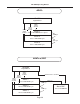


To remove the module, ease it out of the connectors by gently rocking the module back and forth while
pulling upward.
If the module fails to operate correctly, it is most likely reversed or offset in the connectors. Please check
that the orientation is correct before calling technical support.
Installing the System EEPROM
If your existing revision is 1.01 or later, you can check the firmware version you are currently running by
holding down the SOFT LIMIT button during power-up. The code version is shown in the “Over” display LEDs.
The version is shown as long as the button is pressed.
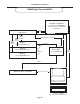
If you obtain a new system EEPROM, install it as follows. Remove the AD-8000 cover as described above.
Locate the EEPROM towards the front of the unit. You will notice that it carries a label indicating the firmware
revision.
NOTE: If you have a Video Sync module installed in your AD-8000, you will need to remove it
before upgrading the system EEPROM. See the instructions in the previous section.
Using a chip-extraction tool, remove the old System EEPROM and recyle it. Carefully insert the new chip
with an appropriate tool, insuring that the chip is oriented correctly and that no pins are bent.
After installation, replace the unit cover as described above.
If the EEPROM is incorrectly inserted, the unit will not operate. Check that the EEPROM is installed cor-
rectly before calling technical support.
Adjusting the Soft Limit Threshold
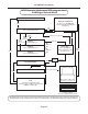
To adjust the Soft Limit threshold, you will need to remove the unit’s top cover and locate the trimpots
labelled with “R-33” plus the channel number. These trimpots are located on the Analog board, which is to the
rear of the unit and extends under the rear panel connectors. Rotating a trimpot clockwise
reduces the Soft
Limit threshold, making the circuit more sensitive. Rotating it counter-clockwise
increases the threshold, mak-
ing the Soft Limit circuit engage at higher levels, thus making it less sensitive.
Grounding
Analog shield grounds are normally tied only to chassis ground. A jumper on each channel, near its XLR con-
nector, can be shorted to connect the shield to analog ground. This is potentially useful for an ungrounded ana-
log source, although it is not recommended under normal conditions.
Changing the Power Input Setting
The power supply to the AD-8000 is set by adjusting an internal switch. A label on the rear of the unit,
adjacent to the power connector, indicates the power supply voltage to which the unit was set on leav-
ing the factory.
If you change the power supply input voltage setting, you should be sure to update the
label accordingly.
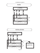
Remove the unit from the rack if so mounted, to expose the top surface of the unit. Ensure that the AD-
8000 is disconnected from AC power input. Remove the top cover screws and examine the inside of the unit.
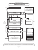
Locate the power supply board. With the front panel towards you, you will see the power supply board at the
right front of the unit. It is recognizable by the large toroidal transformer. Adjacent to the transformer you will
see a large rotary switch marked with AC input voltage values. Rotate the switch to the desired setting with a
coin or large flat-blade screwdriver. If the exact desired voltage is not available on the switch, choose the next
highest value – the AD-8000 will accept input voltages within ±10% of the set voltage without damage or
adverse affects on performance – for example, for a 200 volt input, set the switch to 220v.
After adjusting the setting, replace the top cover and re-install all the screws. Reconnect and re-install the
unit as desired.
AD-8000 Operating Manual
Page 34