
User's Manual


2
The Double Check Valve (DCV) device consists of two
independently acting, spring loaded check valves. Two
resilient seated shut-off valves and four test cocks
complete the assembly.
Each check is designed to maintain a minimum of 1
psi across the valve during normal operation. If at any
time the pressure downstream of the device increases
above the supply pressure, both check valves will
close to prevent any backflow from occurring.
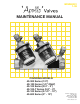
The various styles and sizes of Double Check
Valves are illustrated in figures 1, 2, 3, 4 and 5.
Double Check Backflow Preventer
I DESCRIPTION AND OPERATION
FIGURE 1
FIGURE 2
FIGURE 3
a. The DCV must be installed in an accessible
location to facilitate periodic field testing and
maintenance.
b. Flush all upstream piping thoroughly to remove
foreign matter prior to installing the device.
c. The device should be installed horizontally for ease
of maintenance and testing. A clearance between
the lower most portion of the device and flood
grade or floor should be provided for ease of
maintenance.
d. When shut-off valves are provided separately, they
should be installed with a test cock on the
upstream side of the inlet shut-off valve.
e. After installing the assembly and with downstream
or #2 shut-off valve closed, pressurize the device
and bleed air through test cock #4. Then open #2
shut-off valve.
II INSTALLATION
100 PSIG
99 PSIG
98 PSIG
(NO FLOW CONDITION)
1/2" - 4S-103
(NO FLOW CONDITION)
(40 - 10X - A2)
Y - Pattern
1/2" - 40-103
99 PSIG
98 PSIG
100 PSIG
99 PSIG
98 PSIG
100 PSIG