
User`s manual


User Manual version 2305
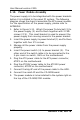
APOLLO 120/150 IV
5-53
APOLLO 150
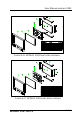
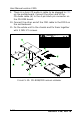
1. Refer to Figure 5-9. The standard LCD used in APOLLO
150 is either 15.1” TTL LG 151X2 or 15” LVDS Chi Mei
M150X3-L01 or their equivalent. The assembly of TTL
LCD differs from that of the LVDS LCD.
2. Fix the LCD panel (1) to the LCD holder (9) with four
PMS 3*8 screws.
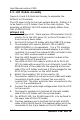
3. For the TTL LCD, LM151X2 or its equivalent, as the
motherboard onboard display is an LVDS controller, to
connect the onboard LVDS controller to the LCD, an
LVDS receiver board is needed.
4. Plug the LVDS board to LCD connector located at the
rear side of the LCD panel first.
5. For the LVDS LCD, M150X3-L01 or its equivalent, no
LVDS receiver board is needed.
6. The APOLLO 150 LCD cable is a DF14-20 to DF11-30
(2*15) cable with around 35 cm in its length. Insert the
DF14-20 end of the cable into the opening at the rear
side of the LCD holder and have it firmly plugged to the
DF11-20 pin connector at the LVDS board or the LCD
panel. The other end is for later connection to the CN3
on the motherboard.
7. Attach the insulator (6) to the invertor (7).
8. The invertor cable (8) for APOLLO 150 is a 7-pin to 4-pin
cable with wafer connectors at both sides. Connect the
7-pin end to the invertor first. The other end is for later
connection to the INV1 on the motherboard.
9. Connect the pink-white high voltage wires from the LCD
to the invertor.
10. The invertor module is to be fixed at the reverse side of
the LCD holder after the LCD module is to be installed to
the system.
11. For APOLLO 150, fix 6 bronze sticks (15 mm) to the
lower sides of the LCD holder. Fix the IR/LED board to
the LCD holder with two 3*6 screws.