
Installation Guide

INSTALLATION
1. Unit must be installed by a licensed plumber/contractor in
accordance with these instructions and state and local
plumbing codes.
2. Proper piping alignment must be observed.
3. Flush all piping thoroughly before installation.
4. Mount the unit so that it is accessible for adjustment, cleaning
and service.
5. Adequate mounting support is recommended.
6. The unit can be installed in any orientation. Make sure that cold
water supply be connected to port “C”, hot water supply to port
“H”, and mixed water discharge to port “M”.
7. Cure times for CPVC joints shall be as recommended by the
adhesive manufacturer or 1 hour minimum, whichever is
greater. Exposure to temperature above 100 °F may require
extended curing times.
8. MAKE SURE THAT WASHER-STRAINER IS ORIENTED TO
ACHIEVE FLAT CONTACT WITH END FITTINGS.
OPERATION
The Apollo “MVB” Series are designed to mix and regulate the amount
of cold and hot water to produce a comfortable and safe outlet
temperature at a predetermined setting, either from the “point of source”
or “point of use” application for single or multiple fixtures.
The thermostatic element which is positioned in the mixing chamber is
connected to an independently seated, balanced and spring-loaded
shuttle/piston, which moves up and down in response to the expansion
and contraction of the element. The spring force acting against the
bottom side of the shuttle will enable the hot inlet port to be normally
open, and the cold inlet port to be normally closed at no flow condition.
When flow demand starts, the thermostatic element will sense the hot
water temperature first, and will immediately expand to allow the shuttle
to move down. This movement decreases the opening area of the hot
water supply, and at the same time increases the opening of the cold
water until certain outlet temperature is maintained. The mechanical
balance of the forces in the shuttle and the sensitivity of the element
determines the proper proportion of incoming hot or cold water to
maintain required outlet temperature. In the event of complete failure of
the cold water supply, the ensuing expansion of the element shuts-off
the hot water supply.
ADJUSTMENT
For optimum performance, it is imperative that the hot water inlet
temperature has a minimum of 15 °F above the desired outlet
temperature. The unit is equipped with a maximum temperature limit
stop and handle locking mechanism to prevent inadvertent adjustment
of the outlet temperature above 120 °F.
1) After the unit is completely installed, turn on the cold water
supply. It is recommended to open the cold side first to avoid
sudden temperature increase in the mixing chamber.
2) When the unit is at no flow condition and pressurized, check
Open end-fixture to establish flow. Observe lock-out/tag-out
procedures when unit is remotely installed from end-fixture.
MIXED TEMPERATURE ADJUSTMENT
1) Remove the handle screw, nameplate and handle.
2) Loosen set screw (1/16” allen wrench) located on the stem
retainer and loosen limit stop (13/16” hex).
3) Slide handle to engage stem and approximately ¼” above
retainer spline.
NOTE: Adjustment cannot be made if the handle and retainer
spline are engaged.
TEMPERATURE LIMIT STOP ADJUSTMENT
1) Once the mixed temperature is adjusted to a desired setting
(not exceeding 120 °F), tighten the limit stop by hand until it
stops against the stem. Do not over-tighten.
2) Tighten set screw to lock the limit stop.
3) In some conditions, the outlet temperature setting is adjusted
above 120 °F. This can be done by loosening the 1/16” set
screw to relieve the lock to the limit stop. Loosen limit stop and
make adjustment to desired setting. Once temperature
stabilized, tighten limit stop and lock set screw.
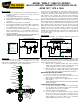
MODEL “MVBLF” (34BLF310 SERIES)
MULTI-PURPOSE THERMOSTATIC MIXING VALVE
ASSE 1017, 1070 & 1069
AQUASTAT
COLD WATER
INLET
HEAT
SOURCE
BOILER,
WATER
HEATER,
ETC.
MIX TEMP
FIXTURES
RECIRCULATION
LOOP
HIGH TEMP.
FIXTURES
HC
H
C
M
MIXING
VALVE
COLD W ATER
INLET
HEAT
SOURCE
BOILER,
WATER
HEATER,
ETC.
MIX TEMP
FIXTURES
HC
H
C
M
TYPICAL INSTALLATION
NO RECIRCULATION SYSTEM
TYPICAL INSTALLATION
WITH RECIRCULATION SYSTEM
HEAT
TRAP
HEAT
TRAP
MIXING
VALVE
- FLOW DIRECTION
- THERMAL EXPANSION
RELIEF VALVE OR TANK
- PRV
- CHECK VALVE
- BALANCING VALVE
- CIRCULATOR/PUMP
- TEMPERATURE GAUGE
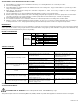
INLET
CHECK VALVE (2)
STRAINER
WASHER (2)
UNION
NUT (3)
TAILPIECE (3)
SPRING
FLOW MIXER
THERMOSTAT
SHUTTLE/PISTON
STEM RETAINER
SET SCREW
LIMIT STOP
HANDLE
NAMEPLATE
SCREW