APOLLO Vacuum Tube Monoblock Power Amplifiers Owner’s Manual Rogue Audio, Inc.
TABLE OF CONTENTS 1) Introduction 2 2) Unpacking the Apollo monoblocks 2 3) Connecting the Apollo monoblocks 3 4) Operation of the amplifiers 4 5) Setting the tube bias 5 6) Troubleshooting 7 7) Registration card 8 8) Fuse values 8 9) Specifications 8 10) Warranty 9 2
INTRODUCTION Congratulations on your purchase decision! We at Rogue Audio truly believe that our amplifiers provide the “smartest” value in high-end audio. If you have never owned a vacuum tube amplifier you will be thrilled by the silky-smooth sound and incredible detail that only a tube amplifier can provide. And with the Apollo monoblock amplifiers, you can be sure that you are getting the very best in tube amplification.
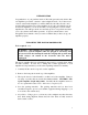
CONNECTING THE APOLLOS INTO YOUR SYSTEM Connecting Apollo to the Loudspeakers: The rear panel has binding posts for both 4 and 8 ohm loudspeakers. The 4 ohm taps are those located closest to the right of the amps rear panel. The 8 ohm taps are located nearest the left side of the rear panel. In general, if your speakers are rated at less than 6 ohms, use the 4 ohm taps and use the 8 ohm taps if they are 6 ohms or greater.
Connecting Apollo to the power outlet: Your Apollo monoblocks have been provided with high ampacity power cords. Use these cords to connect the amplifiers to the wall outlet. It is recommended that you use the same outlet as the preamp to avoid creating a ground loop. It is also recommended that you do not use a power conditioner as it may limit the current available to the amplifiers.
The triode/ultralinear switch allows the user to operate the Apollos in either of the two modes. In general, the sonic differences are subtle but for a given loudspeaker one mode is likely to sound better than the other. There is a complex relationship between the output transformer and the crossover network so try both and see which one works best in your system. This switch can be operated while the amplifier is playing but you will hear a small relay noise through the loudspeaker.
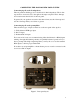
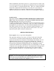
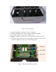
Figure 2. Removable hatchplate 1) 2) 3) 4) Allow the amplifier to warm up for at least 15 minutes. Turn the preamplifier off so that no signal is entering the amplifier Loosen the 4 captive screws on the top hatch cover. Remove the hatch cover. The bias tool is snap attached to the inside of the cover. 5) Locate the toggle switches and associated small potentiometers (they are blue and have a small screw in the top). Note the biasing meter. Figure 3.
6) Make sure that all of the toggle switches are pointed towards the rear of the amplifier. Starting from the left, flip the first toggle switch towards the front of the amplifier. You will see that the meter will rise up to show that the tube’s current is now flowing through the meter. 7) Using the bias tool, slowly turn the screw on the potentiometer that is adjacent to the switch until the bias meter reads 40 miliamps (mA).
OWNER AND WARRANTY REGISTRATION FORM Included with this manual is an Owner and Warranty Registration Form. Please take a minute to fill out this card and return it to Rogue Audio. This card must be returned within 30 days of purchase to validate the warranty.
LIMITED WARRANTY Warranty Period This product has been manufactured under the highest standards of quality and workmanship. Rogue Audio Inc. (hereinafter “Rogue Audio”) warrants this product against defects in material or workmanship as follows: With the exception of vacuum tubes, Rogue Audio warrants to the original purchaser of this product all parts of this product against defects in material and workmanship for a period of three years from the date of retail purchase.