
User's Manual Ethernet ESP6000


User’s Manual
ECM-3612 User’s Manual
47
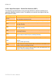
2.3.17 LCD Inverter Connector (J1)
PIN Signal
1 +12V
2GND
3 ENBKL
4VR
5 +5V
Note: For inverters with adjustable Backlight function, it is possible to control the
LCD brightness through the VR signal (pin 4) controlled by VR1 Please see
the VR1 section for detailed circuitry information.
2.3.17.1 Signal Description – LCD Inverter Connecter (J1)
Signal Signal Description
VR Vadj = 5V ~ 0V.
ENBKL LCD backlight ON/OFF control signal.