
User`s manual
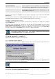

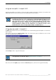
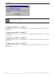


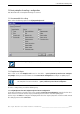
Table Of Contents
- Preliminary remarks
- Introduction
- New functions
- Installation
- Best practice
- Requirements
- Used ports
- Setup
- Upgrade from Apollo 1.3 to Apollo 1.4
- Upgrade from Apollo 1.4 to Apollo 1.4SR1
- Upgrading from Apollo 1.4 to Apollo 1.5
- Upgrading from Apollo 1.5 to Apollo 1.6
- Upgrading from Apollo 1.6 to Apollo 1.7
- Upgrading from Apollo 1.7 to Apollo 1.8
- Upgrading from Apollo 1.8 to Apollo 1.9
- Upgrading the Display Wall configuration
- Control Room Configurator
- Viewer
- Concept
- Apollo 1.9 Viewers
- Limitations
- Memory requirements (minimal RAM size)
- Communication memory
- Requirements
- Steps required to configure the FRG Viewer
- Steps required to configure the Visu Viewer
- Steps required to configure the Cottus Viewer
- Steps required to configure the VNC Viewer
- Steps required to configure the ProViewer
- Steps required to configure the Web Viewer
- Steps required to configure the MPEG Viewer
- Steps required to configure the VTplus Viewer
- Launching Viewer
- Controlling Viewers
- VNC Viewer
- Explorer
- Starting the Explorer
- Explorer User Interface
- Object Tree
- Source Tree View
- Explorer workspace
- Explorer menu bar
- Help menu
- Remote Desktop menu
- Layout Selector menu
- Explorer tool bar
- Device Manager in the Explorer
- Explorer Context Menu
- Drag&Drop functionality
- Layout Editor
- Desktop Server
- Project Backup
- Command Interface
- Device command Interface
- Desktop command Interface
- Viewer command Interface
- Apollo Explorer command interface
- Apollo Layout Editor command interface
- Apollo Layout Selector command interface
- Apollo Remote Desktop command interface
- Apollo Database Convertor command interface
- Apollo Window Detector command interface
- Control Room Bus services
- Control Room Bus
- Serial command interface
- TCPIP command interface
- Application management
- License management
- Time synchronization
- Log file
- Security Provider
- Defining accessGroups
- Configuration of restricted objects
- Permissions
- Restrictions for regions
- Restrictions for layouts
- Restrictions for shortcuts
- Restrictions for advanced menus
- Window Properties|Description
- Window Properties|Sizable
- Window Properties|Always on Top
- Window Properties|Visible
- Edit|Invisible Windows
- Edit|Keyboardinput
- Edit|CommandLine
- Edit|Permissions
- Edit|SaveLayout
- Customized configuration and uninstallation of Apollo
- Soap API Service
- Appendix
- Hotline

4. Installation
Barco – Apollo – DOC-3197-2 – user's manual – Revision 08 – November 2006
__________________________________________________
35/402
4.12 Upgrading the Display Wall configuration
Whenever new and/or additional devices are added to the configuration, this expansion of the Display Wall con-
figuration has to be included into the Visio drawing!
All configuration files (*.ini, *.cn) are generated by the Apollo 1.8 Control Room Configurator.
If the Control Room Configurator was selected when installing individual components and if the
standard directory was used for the installation, then the following folder was created: ...
Program Files\Barco Apollo\Control Room Configurator.
Copy this folder to the following directory:
… \Visio\Solutions
To update an existing visio configuration proceed as follows:
• In Microsoft Visio, open the template Control Room Configuraton.vst.
• Right click into the template to open the context menu.
• From the context menu, select Import and Upgrade Drawing
The dialogs pops up to open a file. Browse for the Visio configuration file of the existing project.
• The file will be imported. At the same time, the shapes are updated.
• Adjust the configuration (add/modify the devices)
• Save the file
• Create the configuration files by means of the command Export Files of the context menu (right mouse
click)
• Copy the configuration files into the folder of the Apollo Project.
Starting with Apollo 1.4 SR3, an existing Apollo Explorer.ini file is automatically
upgraded in case devices which are supported for the first time are added to the
configuration.
This upgrade maintains the existing customizations of e.g. the context menus of the
devices.