
User`s manual
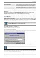

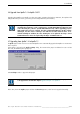
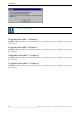


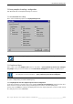
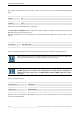
Table Of Contents
- Preliminary remarks
- Introduction
- New functions
- Installation
- Best practice
- Requirements
- Used ports
- Setup
- Upgrade from Apollo 1.3 to Apollo 1.4
- Upgrade from Apollo 1.4 to Apollo 1.4SR1
- Upgrading from Apollo 1.4 to Apollo 1.5
- Upgrading from Apollo 1.5 to Apollo 1.6
- Upgrading from Apollo 1.6 to Apollo 1.7
- Upgrading from Apollo 1.7 to Apollo 1.8
- Upgrading from Apollo 1.8 to Apollo 1.9
- Upgrading the Display Wall configuration
- Control Room Configurator
- Viewer
- Concept
- Apollo 1.9 Viewers
- Limitations
- Memory requirements (minimal RAM size)
- Communication memory
- Requirements
- Steps required to configure the FRG Viewer
- Steps required to configure the Visu Viewer
- Steps required to configure the Cottus Viewer
- Steps required to configure the VNC Viewer
- Steps required to configure the ProViewer
- Steps required to configure the Web Viewer
- Steps required to configure the MPEG Viewer
- Steps required to configure the VTplus Viewer
- Launching Viewer
- Controlling Viewers
- VNC Viewer
- Explorer
- Starting the Explorer
- Explorer User Interface
- Object Tree
- Source Tree View
- Explorer workspace
- Explorer menu bar
- Help menu
- Remote Desktop menu
- Layout Selector menu
- Explorer tool bar
- Device Manager in the Explorer
- Explorer Context Menu
- Drag&Drop functionality
- Layout Editor
- Desktop Server
- Project Backup
- Command Interface
- Device command Interface
- Desktop command Interface
- Viewer command Interface
- Apollo Explorer command interface
- Apollo Layout Editor command interface
- Apollo Layout Selector command interface
- Apollo Remote Desktop command interface
- Apollo Database Convertor command interface
- Apollo Window Detector command interface
- Control Room Bus services
- Control Room Bus
- Serial command interface
- TCPIP command interface
- Application management
- License management
- Time synchronization
- Log file
- Security Provider
- Defining accessGroups
- Configuration of restricted objects
- Permissions
- Restrictions for regions
- Restrictions for layouts
- Restrictions for shortcuts
- Restrictions for advanced menus
- Window Properties|Description
- Window Properties|Sizable
- Window Properties|Always on Top
- Window Properties|Visible
- Edit|Invisible Windows
- Edit|Keyboardinput
- Edit|CommandLine
- Edit|Permissions
- Edit|SaveLayout
- Customized configuration and uninstallation of Apollo
- Soap API Service
- Appendix
- Hotline

5. Control Room Configurator
40/402
__________________________________________________
Barco – Apollo – DOC-3197-2 – user's manual – Revision 08 – November 2006
The template utilizes the three levels "control," "data," and "LAN." These levels are identified with the following
colors.
Level Color
Control red
Data blue
Network green
These levels can be individually hidden or displayed.
The Control Room Configurator makes it possible to depict hardware and software configurations of Barco Dis-
play Wall using the help of specific shapes.
Link lines (connectors) can be attached only at connection points located within the small red, blue, or green
squares.
Red Square: Control Connection
Blue Square: Data Connection
Green Square: Network (LAN) Connection
Links are possible only within one level! Invalid connections/links don't click into the connection points.
Dotted connection lines lead to invalid configuration files! Links are possible only within one
level (color)! Connection lines can be attached only to connection points.
In early Apollo Release, there were two types of protocols to control devices, the Barco
LCD-DLP Agent protocol and the Barco RC Agent protocol. Now the Barco RC Agent can
address and control every device of a Display Wall, and the LCD-DLP Agent is no longer
necessary.
There are 4 template groups:
Template Collection Content
Connectors.vss Connections
Devices.vss Barco Hardware
Software.vss Apollo Software
Third Party.vss Additional Products
Properties have been defined for most objects that can be used to specify parameter values required for the
creation of configuration files.