
User`s manual
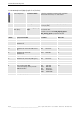
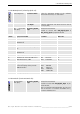
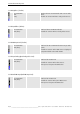
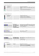
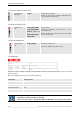
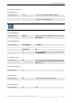

Table Of Contents
- Preliminary remarks
- Introduction
- New functions
- Installation
- Best practice
- Requirements
- Used ports
- Setup
- Upgrade from Apollo 1.3 to Apollo 1.4
- Upgrade from Apollo 1.4 to Apollo 1.4SR1
- Upgrading from Apollo 1.4 to Apollo 1.5
- Upgrading from Apollo 1.5 to Apollo 1.6
- Upgrading from Apollo 1.6 to Apollo 1.7
- Upgrading from Apollo 1.7 to Apollo 1.8
- Upgrading from Apollo 1.8 to Apollo 1.9
- Upgrading the Display Wall configuration
- Control Room Configurator
- Viewer
- Concept
- Apollo 1.9 Viewers
- Limitations
- Memory requirements (minimal RAM size)
- Communication memory
- Requirements
- Steps required to configure the FRG Viewer
- Steps required to configure the Visu Viewer
- Steps required to configure the Cottus Viewer
- Steps required to configure the VNC Viewer
- Steps required to configure the ProViewer
- Steps required to configure the Web Viewer
- Steps required to configure the MPEG Viewer
- Steps required to configure the VTplus Viewer
- Launching Viewer
- Controlling Viewers
- VNC Viewer
- Explorer
- Starting the Explorer
- Explorer User Interface
- Object Tree
- Source Tree View
- Explorer workspace
- Explorer menu bar
- Help menu
- Remote Desktop menu
- Layout Selector menu
- Explorer tool bar
- Device Manager in the Explorer
- Explorer Context Menu
- Drag&Drop functionality
- Layout Editor
- Desktop Server
- Project Backup
- Command Interface
- Device command Interface
- Desktop command Interface
- Viewer command Interface
- Apollo Explorer command interface
- Apollo Layout Editor command interface
- Apollo Layout Selector command interface
- Apollo Remote Desktop command interface
- Apollo Database Convertor command interface
- Apollo Window Detector command interface
- Control Room Bus services
- Control Room Bus
- Serial command interface
- TCPIP command interface
- Application management
- License management
- Time synchronization
- Log file
- Security Provider
- Defining accessGroups
- Configuration of restricted objects
- Permissions
- Restrictions for regions
- Restrictions for layouts
- Restrictions for shortcuts
- Restrictions for advanced menus
- Window Properties|Description
- Window Properties|Sizable
- Window Properties|Always on Top
- Window Properties|Visible
- Edit|Invisible Windows
- Edit|Keyboardinput
- Edit|CommandLine
- Edit|Permissions
- Edit|SaveLayout
- Customized configuration and uninstallation of Apollo
- Soap API Service
- Appendix
- Hotline

5. Control Room Configurator
Barco – Apollo – DOC-3197-2 – user's manual – Revision 08 – November 2006
__________________________________________________
53/402
5.3.2.22 UGX Graphic Card (4channel graphical card)
Custom Properties Resolution Switch
Select the appropriate position of the resolution
switch from the list box, see table below
Color Depth
Select the appropriate color depth (8 bit per pixel or
16 bit per pixel)
Data Connection
Point (blue):
DVI_Analog_Digital_
outpt
PCI board for TransForm A
Possible to connect with VGA_Digital_Input or
VGA_Analog_Input of projection module
switch projection module resolution DDC active
0 OVERVIEW-ML VGA 640×480 no
1 OVERVIEW-ML, OVERVIEW-MD
OVERVIEW-ME
SVGA 800×600 no
2 OVERVIEW-ML XGA 1024×768 no
4 OVERVIEW-MP, ATLAS67C4 (LCD Type D,
E)
XGA 1024×768 no
5 OVERVIEW-MP; ATLAS67C4
OVERVIEW-ME
SVGA 800×600 no
6 digital output, 60 Hz VESA timing SXGA 1280×1024 no
7 OVERVIEW-MP, ATLAS67C4 (LCD Type F) XGA 1024×768 no
8 OverView D series, SXGA SXGA 1280×1024 no
9 Reserved for future use
F digital output with DDC
connected display device provides
DDC information
VGA 640×480
SVGA 800×600
XGA 1024×768
SXGA 1280×1024
UXGA 1600×1200
yes
analog output (CRT) software defined no
5.3.2.23 OmniScaler (TransForm A OmniScaler)
Data Connection
Point (blue):
DVI_Analog_Digital_
outpt
PCI board for TransForm A
Possible to connect with VGA_Digital_Input of pro-
jection module;
Only in conjunction with UGX Graphic Card in Trans-
Form A Processor or TransForm A OmniBus A18 /
TransForm A OmniBus A12