APOLLO Gate Operators, Inc.
CONTENTS Safety Precautions ................................................... 3 Applications .............................................................. 4 Pre-Installation Checklist ........................................ 5 Parts Identification ................................................... 6 Operator Installation ................................................
IMPORTANT SAFETY INSTRUCTIONS WARNING - To reduce the risk of injury or death: • • • • • • READ AND FOLLOW ALL INSTRUCTIONS. Installation should be performed by a professional installer. Required welding should be performed by a qualified welder. Should electricity be required, use a certified electrician only. Any device that requires 120 Volts AC should be U.L. approved.
APPLICATIONS The Apollo Model 1500/1600 Swing Gate Operator is designed to handle swing gates up to 14 feet in length and 400 pounds each. A professional fence or gate dealer is recommended to assure proper installation. Apollo Gate Operators are available only through qualified dealers with an outstanding reputation in the fence and gate industry. These dealers will be able to recommend the proper equipment for particular applications. Apollo Gate Operators are 12 Volt DC (Direct Current) powered.
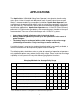
PRE-INSTALLATION CHECKLIST The following checklist should be used before beginning installation: Verify that the proper operator has been selected for this application. Verify proper installation and operation of the gate. 1. Are the hinges servicable? 2. Does the gate swing free and level? 3. Will the gate require a locking device? 4. Is the hinge and stop posts sturdy enough to handle the gate & operator? Determine the general location of the operator, attachment points, and solar panel (if used). 1.
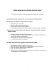
PARTS IDENTIFICATION Actuator with 8’ cable (slave actuator with 38’ cable supplied with 1600) Control Box Pivot Arm (2 with 1600) Gate Bracket (2 with 1600) Hardware Kit (2 with 1600) Bolt On Pivot Arm (optional) (2 required with 1600) CAUTION Signs (2 each) (4 each with 1600) 5 Watt Solar Panel & Bracket (optional) (2 required with 1600) Automatic Battery Charger (optional) 6
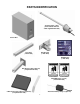
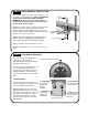
OPERATOR INSTALLATION STEP 1 PIVOT ARM INSTALLATION (standard pull to open) Location of Pivot Point. Notes: PULL TO OPEN pulls gate open (actuator is extended when gate is in the closed position). PUSH TO OPEN pushes the gate open (actuator is retracted when gate is in the closed position). For PUSH TO OPEN installations see page 11. If a 400 Upgrade Kit is to be used, refer to the 400 instructions for pivot point location. The following instructions provide up to 105o of swing.
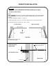
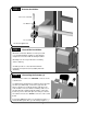
STEP 2 Actuator Installation 1/2” x 3 1/2” Hex Bolt 1/2” Washer 1/2” Lock Nut Do not over tighten nut STEP 3 Control Box Installation Mount the control box within 4 feet of the pivot arm. Use mounting hardware capable of supporting the weight of the control box with the battery installed. Mounting holes are not provided since mounting surfaces will vary. Set battery inside of control box with terminals toward the front (Do not use any battery with side terminals).
STEP 5 GATE BRACKET INSTALLATION Activate push button on the side of the control box and extend the actuator until it stops (PULL TO OPEN only, leave actuator retracted for PUSH TO OPEN). WARNING: Do not let extension tube rotate as it extends. Do not insert fingers or tools in the hole at the end of the extension tube Align the hole in the end of the actuator extension tube with the holes in the gate bracket and locate gate bracket mounting position with the gate in the closed position.
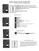
635/636 CONTROL BOARD CONNECTIONS 8 Pin White Connector (two on 636 Master & Slave) 7 8 5 6 3 4 1 2 1 ORANGE - Open Limit Input (Normally open unless gate is opened) 2 WHITE - Close Limit Input (Normally open unless gate is closed) 3 BLACK - Motor - Positive during open cycle, Negative during close cycle 4 RED - Motor - Negative during open cycle, Positive during close cycle 5 GREEN - Ground (Limit Switch Common) 6 Ground Not used 7 BLACK - Ground - Battery Negative 8 RED - Battery Positive (+12 VD
635/636 CONTROL BOARD ADJUSTMENTS OFF ON PROGRAM SWITCHES Factory Setting Description #1 ON TIMER TO CLOSE - Automatically closes gate ON - Close timer enabled OFF - Close timer disabled #2 OFF CURRENT SENSITIVITY OPTION - Delays current sensing from start ON - 4 second delay OFF - 2 second delay #3 ON #4 OFF #5 OFF #6 OFF #7 ON #8 ON #9 OFF TIMER TO CLOSE OPTION ON - timer to close works only when open limit switch is activated OFF - timer to close works from any open gate position
PUSH TO OPEN INSTALLATION STEP 1 PIVOT ARM (s) INSTALLATION Location of pivot point Direction of opening Hinge post Gate (closed) 6” Both measurements are taken from the center of the hinge. Top View 11” Center Line of attachment point for gate bracket Vertical position of pivot arm (s) 1/2” Pivot arm must be level Front View Hinge post Rewiring actuator (s) for push to open Must be re-wired for proper operation Strip back 6” of black sleeve from connector end of the actuator cable.
APOLLO Gate Operators RECEIVER OPTIONS Do not confuse the receiver code switches with the red program switches on the gate control board. Never set all code switches to the same position. Transmitters must match code switches for proper operation.
TROUBLESHOOTING OPERATOR & ACCESSORIES Some troubleshooting will require a hand held multimeter. An inexpensive digital multimeter may be purchased at Radio Shack or a local electric supply company. Refer to the owners manual for instructions. SYMPTOM Gate opens OK but after closing, opens back up. 1. Excessive closing pressure on gate. Re-adjust the close limit switch on the actuator. 2. Automatic reverse sensitivity is set too sensitive.
SYMPTOM Gate will open using push button on side of box, but not with transmitter. 1. Code switches do not match. Check that the code switches in the transmitter and the receiver match. 2. Low or dead battery in transmitter. Replace battery. 3. Fuse blown on circuit board. Check fuses on gate control board. 4. Low battery in operator. Battery voltage should be 12 to 14 volts under load. 5. Replace receiver. SYMPTOM Transmitter works, but not very far.
SYMPTOM Gate will not open or close. Disconnect the solar panel or charger and measure the battery voltage. Battery should read 12 or more volts and never drop below 11 volts when gate is operating. Reset program switches to factory setting. # 1,# 3,# 7,# 8 ON, all others OFF. RED & WHITE PROGRAM SWITCHES 1 ON 2 off 3 ON 4 off 5 off 6 off 7 ON 8 ON 9 off Disconnect all accessories from the circuit board - receivers, push buttons, keypads, loops, phones, intercoms, etc.
APOLLO Gate Operators, Inc. LIMITED TWO-YEAR WARRANTY Apollo Gate Operators are warranted against defects for a period of 24 months from the date of purchase, providing recommended installation procedures are followed.