Service Source MacBook (13-inch) MacBook (13-inch) MacBook (13-inch Late 2006) MacBook (13-inch Mid 2007) Updated 1 June 2007 © 2006, 2007 Apple Inc. All rights reserved.
MacBook (13-inch) Contents Take Apart General Information 7 What’s New 7 Product Configurations 8 Vertical-Insert Connectors 10 Tools 10 Power Adapter 11 Temperature Concerns 11 Note About Images in This Manual 11 Logic Board Springs 12 Simplified Flowchart for Take Apart 13 Battery 14 RAM Door (L-Bracket) 17 Memory (DIMMs) 21 Removal Procedure 22 Replacement Procedure 23 Removing a Stuck Memory Card 25 Hard Drive 26 Top Case (with Keyboard) 29 Trackpad Cable (Late 2006 Model Only) 41
Heatsink 74 Checking the Thermal Grease 78 Comparing Heatsinks 84 Bluetooth Holder 85 Optical Drive 89 Handling Slot-Load Optical Drives 99 Removing a Stuck Disc from an Optical Drive 103 Optical Drive Cable 105 I/O Frame (with upper EMI shield) 109 Logic Board 113 DIMM Lever Kit 122 Backup Battery 126 Bluetooth Antenna Board and Cable 129 Bluetooth Board 133 Bluetooth-to-Logic Board Cable 137 Subwoofer with Right Speaker Cable 142 Midframe 148 Display Bezel 153 Removal Procedure 15
Clutch Cover 193 Bezel Scoops, Left and Right 199 LCD Panel 203 Antenna Receptors and Cables, Top and Left 209 Antenna Receptor and Cable, Right (Late 2006 Model Only) 214 LCD Panel Assembly 222 Removal Procedure 224 Reinstallation Procedure 229 Foil at Camera Bracket (Original MacBook Model) 237 Spacers at Camera Bracket 240 Camera Assembly 242 LVDS Cable with USB Line 248 Microphone Cable 255 Inverter Board 262 Inverter Cable 265 Display Hinges, Left and Right 268 Bezel Brace, Left 271
Part Location 304 Procedure 305 Troubleshooting General Information 320 Troubleshooting Steps 321 Symptom Charts 324 Block Diagram 334 Views External and Internal Views 337 Front: Keyboard and IR Window 337 Back: Air Vents and Display Clutch 338 Left Side: Ports 338 Right Side: Slot Drive 338 Battery Bay: Memory Card Levers and Hard Drive Pull Tab 339 Top Case Removed: Main Modules and Cable Routing 339 Screw Matrix 345 Top Case Screw Locations 345 Display Module Screw Locations 346 Lo
Service Source Take Apart MacBook (13-inch) © 2006, 2007 Apple Inc. All rights reserved.
General Information What’s New The MacBook (13-inch) portable computer is the first computer of its size featuring the Intel Core Duo processor and built-in iSight video camera. The main features and service differences (from similar-sized Apple portable computers) include: • Higher resolution 13.
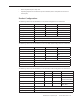
• • Built-in keyboard as part of top case Operating temperature is hotter than previous models (refer to “Temperature Concerns” in this chapter) Product Configurations The following table shows the MacBook (13-inch) model configurations at introduction: Feature Good Better Best Intel Core Duo processor 1.83 GHz 2.0 GHz 2.0 GHz Memory 512 MB (x2) 512 MB (x2) 512 MB (x2) Hard Drive 60 GB 60 GB 80 GB (120 GB) Optical Drive Combo, 9.5 mm Super, 9.5 mm Super, 9.
Keyboard integral to top case: Product name on display bezel: MagSafe power connector port: Infrared window on front of computer: For additional views of the computer, refer to the “Views” chapter at the end of this manual.
Vertical-Insert Connectors Most of the cable connectors on the logic board use a new design that requires special insertion and extraction. Caution: To prevent damage to the connectors, install them from the front (away from the cable) when reconnecting vertical-insert cables to the logic board. Tools Caution: To prevent scratches or other cosmetic damage to the computer housing, use a soft cloth as a protective layer when removing and installing the external screws.
Power Adapter Warning: The power adapter for this computer is unique to this model. It uses an MPM 4-pin adapter plug. Do not use this power adapter with any other portable computer. Power adapters from earlier iBook or PowerBook computers are not compatible and will not fit the MPM plug. Temperature Concerns This computer runs hotter than previous models. However, the normal operating temperature is well within national and international safety standards.
Logic Board Springs Caution: When servicing the computer, be especially careful when working near the two springs on the logic board. Although the springs are flexible, they can be inadvertently torn, bent, or broken if a cable gets caught on them. A logic board might be considered unusable with one or more damaged springs. Check the structural integrity of the springs before completing a repair.
Simplified Flowchart for Take Apart Although this flowchart does not include every serviceable part, you can use it as a reference after becoming familiar with the detailed removal procedures.
Battery Tools • • Clean, soft, lint-free cloth Coin Part Location Preliminary Steps Warning: Always shut down the computer before opening it to avoid damaging the internal components or causing injury. After you shut down the computer, the internal components can be very hot. Let the computer cool down for 30 minutes before continuing Procedure 1. Shut down the computer.
2. Wait 30 minutes to allow the computer’s internal components to cool. 3. Unplug all external cables from the computer except the power cord. 4. Unplug the power cord. 5. Put on an ESD wrist strap. 6. Turn over the computer and place it on a soft cloth. 7. Use a coin to release the battery latch. Turn the coin a quarter turn clockwise to unlock the battery. Caution: To prevent scratches or other cosmetic damage to the bottom case, use only a coin to unlock and lock the battery. 8.
10. Reassemble and test the computer.
RAM Door (L-Bracket) Tools • • • • Soft cloth ESD wrist strap and mat Magnetic Phillips #0 screwdriver Black stick (Apple part number 922-5065) or other nonconductive nylon or plastic flatblade tool Preliminary Steps Before you begin, remove the battery.
Procedure 1. With the computer closed and upside down on a soft cloth, touch a metal surface inside the battery bay to discharge any static electricity. 2. Loosen—but do not try to remove—the three captive screws along the RAM door.
3. Holding the long end of the L-shaped RAM door, pivot it out from the battery bay. (If necessary, use a black stick to tilt it up and out of the battery bay.) Be careful not to bend it.
4. Replacement Note: Install the replacement RAM door by first aligning the short end at the notch near the hard drive opening. Replacement Note: Use a black stick, if necessary, to tuck in the EMI gaskets so they do not protrude from the edge of the battery bay. Make sure the three screws align with the holes in the bottom case before tightening them. 5. Reassemble and test the computer.
Memory (DIMMs) This computer comes with a minimum of 512 MB of 667 GHz Double Data Rate 2 (DDR2) Synchronous Dynamic Random-Access Memory (SDRAM) installed. It has two slots that can accept SDRAM Small Outline Dual Inline Memory Modules (SO-DIMMs). The slots are side-by-side on the logic board behind the RAM door. For best performance, memory should be installed as pairs with an equal memory card in each slot. The maximum amount of memory for this computer is 2 GB, with 1GB DIMM installed in each slot.
Removal Procedure 1. Touch a metal surface inside the battery bay to discharge any static electricity. 2. Put on an ESD wrist strap. 3. In one swift motion, use one finger to move the lever to the left and release it. This swift motion ejects the memory card. Caution: The memory card eject levers are on a spring hinge that operates on a side-to-side horizontal plane. The mechanism can be damaged if the lever is forced outside of that horizontal movement.
4. Holding the memory cards by the corners, slide them out from the battery bay. Important: Do not touch the gold connectors. Handle the card only by its edges. Note: A memory card might show a white residue when you remove it. This harmless substance acts as a lubricant when installing the memory card at the factory, but it is not required when reinstalling a memory card. Replacement Procedure 1. Align the memory card so that the gold connectors face the slot and the notch is on the left.
2. Use two fingers to push firmly on the edge of the memory cards. If there is a tight fit, installing the cards may take some force to ensure that they are fully inserted. Important: When the cards are fully inserted, the edges of the cards are nearly hidden, as shown by the recessed card on the right in the image below. 3. If the levers do not return to the closed position, move them to close them. 4. Reassemble and test the computer. 5.
Removing a Stuck Memory Card If a lever becomes inoperable and does not eject a memory card, you must remove the top case to access the stuck memory card. Follow this procedure only if the memory card is stuck and cannot be ejected by using the lever. 1. Follow the “Top Case” procedure in this chapter to remove the top case. 2. Notice the eject bars on each side of the memory card carrier. Use a black stick to push and slide the eject bar down the side of the carrier. 3.
Hard Drive Tools • • ESD wrist strap and mat Black stick (Apple part number 922-5065) or other nonconductive nylon or plastic flatblade tool Preliminary Steps Before you begin, remove • Battery • RAM door Part Location MacBook (13-inch) Take Apart — Hard Drive 26
Procedure 1. If the hard drive pull-tab is tucked in, use a black stick to unroll it. 2. Pull the tab straight out to slide the drive out from the rubber rails in the battery bay.
3. Hold the drive only by the sides when removing and replacing it. 4. Install the replacement hard drive, and reassemble and test the computer. Important: After a new hard drive replacement, you must update the operating system to Mac OS X version 10.4.6 or later. Replacement Note: If you are installing the hard drive while the top case is off, make sure the two bottom case spring guides are aligned with the notches in the bottom case.
Top Case (with Keyboard) Tools • • • • • • ESD wrist strap and mat Magnetic Phillips #0 screwdriver Magnetic Phillips #00 screwdriver (preferably with a long handle) Black stick (Apple part number 922-5065) or other nonconductive nylon or plastic flatblade tool Access card (Apple part number 922-7172) to open the top case Clean, soft, lint-free cloth Preliminary Steps Before you begin, remove • Battery • RAM door Part Location MacBook (13-inch) Take Apart — Top Case 29
Procedure Caution: To prevent scratches or other cosmetic damage to the computer housing, use a soft cloth as a protective layer when removing and installing the external screws. 1. With the computer upright, remove the two identical 5.5-mm long shoulder screws from the right side of the computer. Replacement Caution: When installing these top case screws, do not press on the area over the slot drive. The slot-drive bezel could be damaged with too much pressure. 2.
4. Turn over the computer, and on the outside of the bottom case, remove the three #0 Phillips screws: • Two 14-mm long screws near display hinge • One 11-mm long at center of bottom case Replacement Caution: Do not put one of the longer screws in the center screw hole or it will damage the logic board. Replacement Caution: When installing the three bottom case screws, install them in the order shown.
5. Notice the long row of #0 Phillips screws at the front edge of the battery bay. 6. Important: Remove only the four screws shown. Remove the 3-mm long identical screws as follows: Starting at the corner closest to the battery connector, skip the first screw, then remove the second, fourth, seventh, and ninth screw. Tip: To help remember the screw sequence, think of it as “2, 4, 7, 9 loosens the top case every time.” 7.
8. In the battery bay, use a long-handled screwdriver to remove the three #00 Phillips screws at the inner edge of the battery bay near where the RAM slots are located: • Two identical 3-mm long screws • One longer 4.5-mm long screw at the corner of the battery bay nearest the battery connector Because this is a recessed area, the screwdriver has to go in at an angle. Keep the screwdriver in line with the screw head as much as possible.
11. With the top and right side gap opened, tilt up—but do not remove—the right edge of the top case. This motion releases the remaining snaps between the top case and bottom case, and the slot-load bezel clips become loose as the top case is tilted up.
12. Raise up the top case so you can see where the folded trackpad flex cable attaches to the logic board.
13. Use the flat end of a black stick to reach in and disconnect the trackpad cable. For the Late 2006 model, use the pull-tab to disconnect the trackpad cable.
14. Lift the top case up and away from the computer assembly.
15. Refer to the following notes to install the replacement top case, and reassemble and test the computer. Replacement Note: The top case includes heatstaked keyboard, webbing, EMI shield, a small rectangular foam pad, and attached trackpad cable. Replacement Note: Before replacing the top case, make sure to connect the trackpad flex cable to the logic board.
Replacement Caution: If any of the four bezel clips at the slot-load bezel come loose, simply insert them back in the slots. Make sure they are in place while reassembling the computer and before installing the top case. Install the right side of the top case first (near the disc bezel) to lock the bezel clips and prevent any of the clips from becoming loose inside the computer. Replacement Note: Install the right side of the top case first (near the disc bezel).
Replacement Note: When installing the screws at the rear corners of the bottom case, insert an access card tool between the top case and the display to maintain light pressure as the screws are tightened.
Trackpad Cable (Late 2006 Model Only) Tools • • ESD wrist strap and mat Black stick (Apple part number 922-5065) or other nonconductive nylon or plastic flatblade tool Preliminary Steps Before you begin, remove • Battery • RAM door • Top case with keyboard Part Location MacBook (13-inch) Take Apart — Trackpad Cable (Late 2006 Model Only) 41
Procedure 1. Place the top case (keyboard side down) on a clean surface. Replacement Note: Refer to the following image when attaching a replacement trackpad cable. The folds in the cable and the areas that adhere to the top case should appear as shown. 2. Use a black stick to start to peel up the clear strip of tape.
3. Hold the trackpad cable in place as you peel up—but do not remove—the tape. 4. Peel up the mylar shield that protects the trackpad circuitry.
Note: The shape of the mylar shield may differ slightly. This one includes a squared-off tab: 5. Caution: The trackpad cable locking lever at the top of the connector is fragile. Use a black stick to carefully tilt up the lever until it is vertical (as shown by the detailed image on right). Replacement Note: When locking the trackpad cable lever, make sure it is completely closed, as shown by the detailed image on left below.
6. With the cable locking lever open, pull the cable down to remove it from the connector. 7. Carefully peel up the trackpad cable from where it adheres to the underside of the top case. 8. Install the replacement trackpad cable, and reassemble and test the computer.
AirPort Extreme Card Tools • • • ESD wrist strap and mat Black stick (Apple part number 922-5065) or other nonconductive nylon or plastic flatblade tool Magnetic Phillips #0 screwdriver Preliminary Steps Before you begin, remove • Battery • RAM door • Top case with keyboard Part Location MacBook (13-inch) Take Apart — AirPort Extreme Card 46
Procedure Caution: When servicing the computer, be especially careful when working near the two springs on the logic board. Although the springs are flexible, they can be inadvertently torn, bent, or broken if a cable gets caught on them. A logic board might be considered unusable with one or more damaged springs. Check the structural integrity of the springs before completing a repair. 1. Remove the 8.
3. Pull the card up slightly and out of the card socket on the logic board. 4. Use a black stick to move aside the speaker cable. 5. Disconnect the two cables from the AirPort Card. Note that the black cable is on the left and the gray cable is on the right. Tip: To remember the cable locations, think “Left = bLack; Right = gRay.
Late 2006 Model: This model has three antenna cables. Disconnect the black, blue, and gray cables. 6. Install the replacement AirPort Card, and reassemble and test the computer. Replacement Note: If the computer model that you are servicing includes tape over the antenna cables, reapply the tape where shown.
Late 2006 Model Replacement Note: Notice that the AirPort Card has numbers 2, 1, and 0 printed on the card. The numbers correspond to the antenna cable colors where 2 = black, 1 = blue, and 0 = gray. Replacement Caution: When connecting the AirPort antenna cables, make sure the cables do not obstruct the gold-colored spring on the logic board. If one of the cables were caught in the folds of the spring, the cable or spring could be damaged when the top case was installed.
MagSafe DC-In Board Tools • • • ESD wrist strap and mat Magnetic Phillips #0 screwdriver Black stick (Apple part number 922-5065) or other nonconductive nylon or plastic flatblade tool Preliminary Steps Before you begin, remove • Battery • RAM door • Top case with keyboard Part Location MacBook (13-inch) Take Apart — MagSafe DC-In Board 51
Procedure 1. Place a black stick under the DC-in connector cables to help disconnect the connector, then pull the connector away from its connection on the logic board. (Note: Although the cables are solid black on the Late 2006 model, the steps are the same.) 2. Remove the 3-mm long screw from the MagSafe DC-in board. Caution: The DC-in port is magnetic. Be careful that it doesn’t pick up screws or other small parts.
3. From the port side, use a black stick to help tilt up the MagSafe DC-in board and remove it from the logic board. Replacement Note: Make sure the folded side of the EMI shield fits over the I/O frame rib so that the rib is sandwiched between the flanges of the EMI shield. Replacement Note: If installing a new MagSafe DC-in board, first peel off the protective membrane from the MagSafe DC-in board.
4. Install the replacement MagSafe DC-in board, and reassemble and test the computer. Replacement Note: Check that there are no bent EMI fingers on the shield covering the port area. Replacement Note: Check the port side of the bottom case to make sure the MagSafe DC-in port is level with the port opening.
Left Speaker Tools • • • ESD wrist strap and mat Magnetic Phillips #0 screwdriver Black stick (Apple part number 922-5065) or other nonconductive nylon or plastic flatblade tool Preliminary Steps Before you begin, remove • Battery • RAM door • Top case with keyboard Part Location MacBook (13-inch) Take Apart — Left Speaker 55
Procedure 1. Disconnect the speaker cable from the logic board. 2. Remove the 8.5-mm long ground screw at the upper right corner of the AirPort Extreme Card. 3. Route the cable underneath the AirPort cables.
4. Remove the 6-mm long speaker screw. 5. Pull up on the speaker cable to remove it from the frame. 6. Pivot up the speaker from the left corner.
7. Route the speaker cable underneath the DC-in cable. 8. Install the replacement speaker cable, and reassemble and test the computer. Replacement Note: To prevent a pinched cable, make sure the cable is routed as shown.
Battery Connector with Sleep Switch Tools • • • ESD wrist strap and mat Magnetic Phillips #0 screwdriver Black stick (Apple part number 922-5065) or other nonconductive nylon or plastic flatblade tool Preliminary Steps Before you begin, remove • Battery • RAM door • Top case with keyboard Part Location MacBook (13-inch) Take Apart — Battery Connector with Sleep Switch 59
Procedure Caution: Do not touch the raised section of the sleep switch connector. It is fragile and could break. 1. Remove the two 4.5-mm long shoulder screws from the frame at the battery connector. Replacement Caution: Make sure the screws are the proper length. A longer screw could damage the board.
2. Tilt up the battery connector end of the board. 3. If provided, remove the single screw that secures the battery cable clip to the I/O frame.
4. Tilt up the battery cable clip, and remove it from the computer assembly. Replacement Note: Be sure to install the battery cable clip when reassembling the computer.
5. Caution: Do not touch the raised section of the sleep switch connector. It is fragile and could break. Using a black stick, insert it under the cables, and lift up the connector from the logic board. Replacement Note: To avoid bending the pins on the sleep switch connector card, make sure you squarely align the pins over the logic board and keep the connector card level when installing it. Install the “pins” end of the sleep switch connector first; then install the battery connector and screws.
6. Install the replacement battery connector with sleep switch, and reassemble and test the computer. Caution: To avoid pinching the cable, the battery connector cable must be properly tucked into the cable channel, as shown by the image on the left, below: Replacement Note: Check that the battery connector can be wiggled to allow for movement of the battery. If the connector is completely still when grasped, loosen the screws slightly.
Hard Drive Connector Tools • • • ESD wrist strap and mat Magnetic Phillips #0 screwdriver Black stick (Apple part number 922-5065) or other nonconductive nylon or plastic flatblade tool) Preliminary Steps Before you begin, remove • Battery • RAM door • Hard drive • Top case with keyboard Part Location MacBook (13-inch) Take Apart — Hard Drive Connector 65
Procedure 1. Remove the two 6-mm long screws from the hard drive connector at the right front side of the computer. 2. Carefully lift up the hard drive connector from the bottom case. This action automatically disconnects the hard drive board from the sleep LED/IR receiver flex cable.
Replacement Caution: Note the tiny connector at the end of the hard drive board. It connects to the sleep LED/ IR receiver board at the front right corner of the computer via a tiny flex cable. To reinstall the flex cable, first peel up the end of the snubber to access the length of the flex cable. Carefully peel up the flex cable from its adhesive. Using a black stick, tilt up the tiny flex cable at the right corner.
3. Pull up the hard drive connector cable that runs along the bottom edge of the optical drive. Note the three cable routing guides when reinstalling the cable. 4. Use the two pull tabs to disconnect the optical drive flex cable and the LVDS cable.
5. Use the pull tab to disconnect the hard drive connector cable. 6. Route the hard drive connector cable under the black cables.
7. Install the replacement hard drive connector, and reassemble and test the computer.
Fan Tools • • • ESD wrist strap and mat Magnetic Phillips #00 screwdriver Black stick (Apple part number 922-5065) or other nonconductive nylon or plastic flatblade tool Preliminary Steps Before you begin, remove • Battery • RAM door • Top case with keyboard Part Location MacBook (13-inch) Take Apart — Fan 71
Procedure 1. Peel up the strip of tape that overlaps the fan near the optical drive. 2.
3. Tilt up the fan and disconnect the fan cable from the logic board. 4. Holding the fan tilted up from the bottom case, peel away the adhesive foam that overlaps the fan and the heatsink. Replacement Note: Because the foam strip tears easily, be sure to install a new strip of adhesive foam before reassembling the computer. 5. Install the replacement fan, and reassemble and test the computer. Replacement Note: Make sure the cables are fully tucked in the channel between the fan and the optical drive.
Heatsink Tools • • • • • • ESD wrist strap and mat Magnetic Phillips #0 screwdriver Black stick (Apple part number 922-5065) or other nonconductive nylon or plastic flatblade tool Alcohol wipes Thermal grease syringe (Apple part number 922-7144) Felt-tip pen (optional) Preliminary Steps Before you begin, remove • Battery • RAM door • Top case with keyboard • Fan Part Location MacBook (13-inch) Take Apart — Heatsink 74
Procedure 1. Remove the four identical 8-mm long screws from the heatsink. Note that the screw at the lower right corner anchors a flexible ground tab for the speaker cable that runs along the top of the RAM card carriers. Make sure the tab is sandwiched between the heatsink and the screw when it is reinstalled.
2. Starting at the lower bracket of the heatsink, start to tilt it up to loosen it from the logic board. 3. Holding the heatsink by its edges, tilt it up and disconnect the two thermistor connectors from the logic board.
Replacement Caution: When installing the heatsink, make sure its two thermistor cables are routed as shown to prevent cable damage. Replacement Note: Make sure you install the thermal sponge over the two thermistor connectors. 4. Important: Anytime the heatsink is removed (even if it is to replace another module), check the thermal grease as described in the following section.
Checking the Thermal Grease Warning: Whenever the heatsink is separated from the logic board (even if you are installing the same heatsink or board), the thermal grease must be checked and possibly replaced. Failure to do so can cause the computer to overheat and be damaged. 1. With the heatsink removed, check the underside of the heatsink: • If it has a thin sheet of transparent film covering the square heatsink pads and preapplied thermal grease, then you do not need to reapply thermal grease.
• If the thermal grease is directly on the heatsink pads (as shown in step 2), continue with the remaining steps in this procedure. 2. Caution: This step is required only when the heatsink and logic board are removed to replace a later part (such as the bottom case) and the same heatsink and logic board will be re-installed in the computer. Use a black stick to remove as much thermal grease as possible from the two chips on the logic board and the two pads on the heatsink. 3.
4. Use an alcohol wipe to completely clean the two pads on the heatsink. 5. Caution: The syringe steps for this procedure are required only when the heatsink and logic board are removed to replace a later part (such as the bottom case) and when no new heatsink with pre-applied thermal grease will be installed. Refer to the heatsink conditions in step 1 for details before attempting to replace the thermal grease. Note the contents of the syringe of thermal grease.
6. Using the syringe, put a 0.1 to 0.12 cc dab of thermal grease, in the center, on the mating surfaces of both chips, as shown below. Apply the grease only up to the line that you marked on the syringe. Important: Use one-third of the syringe contents per chip, so in this case, 1/3 of the thermal grease will be left in the syringe when you are done. Although the amount shown appears to be plenty of grease, this is the correct amount that has been tested and verified on the production line.
7. While centering the heatsink pads over the two chips, lower the heatsink onto the logic board and press on the areas where the screw brackets on the heatsink meet the standoffs on the board. Make sure the heatsink is level on the board before installing the screws. 8. Install the heatsink (using the screw sequence shown below), and reassemble and test the computer. Note: Make sure the heatsink includes the gray, adhesive sponge strip that sticks to and runs along the top of the copper pipe.
. Replacement Note: If you replaced the heatsink from a kit that includes the thermal sponge, install the thermal sponge over the two thermistor connectors. Make sure the connectors are fully seated. • Remove the adhesive backing from the sponge, and place the sponge adhesive side • down over the two connectors. Make sure the sponge sticks to and completely covers both connectors. (The actual • color and appearance of the sponge may vary slightly from what is included in the kit.
Comparing Heatsinks The heatsink referred to as a 1.2 mm heatsink can be identified by the number 607-0142 on its label and its thin rectangular thermistor connectors. Order Apple part number 076-1242 (which includes the heatsink, thermal tape, and sponge) to replace a 1.2 mm heatsink. The heatsink referred to as a 1.0 mm heatsink can be identified by the number 607-0199 on its label and its thick square thermistor connectors.
Bluetooth Holder Important: The Bluetooth holder is included with a replacement optical drive and should not be removed unless it is damaged or no longer sticks to the optical drive housing.
Procedure 1. Insert a CD or DVD disc half way into the slot drive to help support the drive and prevent damage. 2. Use a black stick to slide out the Bluetooth board from its holder.
3. Warning: To prevent damage to the optical drive, do not touch or press anywhere else on the drive. 4. Use a black stick to carefully pry up the Bluetooth holder from the top of the optical drive. Make sure you use as little pressure as possible to prevent damage to the drive. Replacement Note: Peel off the adhesive backing from the Bluetooth holder and apply it to the drive where shown. Press the holder lightly to make sure it adheres to the drive.
5. Install the replacement Bluetooth holder, remove the optical drive disc, and reassemble and test the computer.
Optical Drive Tools • • • ESD wrist strap and mat Magnetic Phillips #0 screwdriver Black stick (Apple part number 922-5065) or other nonconductive nylon or plastic flatblade tool Preliminary Steps Before you begin, remove • Battery • RAM door • Top case with keyboard Part Location MacBook (13-inch) Take Apart — Optical Drive 89
Procedure 1. With the computer assembly on a clean, scratch-proof surface, locate the Bluetooth board and holder. Note that the Bluetooth holder stays with the drive and is included with a replacement optical drive.
2. Tilt up the Bluetooth board from the upper right corner of the optical drive. 3. Disconnect the optical drive flex cable from the logic board.
4. Peel up the tape from the optical drive. 5. Carefully lift up or move aside the cables to remove the single 5.5-mm long screw at the mounting bracket. You might first need to disconnect the ground screw by the speaker to loosen the cables and access the mounting bracket screw.
6. Use a black stick to slide the mounting bracket forward (away from the body of the drive and toward the fan) to disengage it. 7. Slide out the hard drive, and set it aside.
8. Access the two identical 3-mm long screws along the bottom edge of the drive at the hard drive snubber. (If the snubber is blocking one of the screws, carefully peel up the snubber.) 9. Lift up the cable that runs between the drive and the snubber at the lower edge of the optical drive.
10. Warning: Handle the optical drive at the side edges only. Do not touch or press anywhere else on the drive. Refer to the next section, “Handling Slot-Load Optical Drives.” 11. Grasp the optical drive flex cable and use it as a pull tab as you tilt up the optical drive. Be careful where it can catch on cables. Replacement Note: Make sure the mounting bracket on the optical drive is pushed in before placing the optical drive in the bottom case.
Replacement Note: If you are installing a replacement drive, check that the sliding bracket that is secured with two screws slides easily and is not too tight. If it is too tight, loosen the screws just enough so the bracket slides with ease.
12. Before installing the optical drive, make sure the cables on the bottom case are routed as shown.
13. Install the replacement optical drive and reassemble and test the computer. Late 2006 Model: (The blue tape is for controlling vibration; do not remove the tape) Important: For best performance after a new optical drive replacement, be sure to update the operating system to the latest Mac OS X version.
Handling Slot-Load Optical Drives Follow the instructions in this section carefully. This procedure shows how to handle slot-load optical drives when they are outside the computer. • Observe ESD (electrostatic discharge) guidelines when handling optical drives.
• Handle the drive only by the sides and back edge. • Do not touch the front of the drive.
• Do not press on the drive or lift it by the top and bottom cover. • Do not handle the drive by the gull wing edge only.
• When storing optical drives, use approved packaging boxes. Never stack loose drives. • When returning a defective optical drive, use the original packaging and an antistatic bag. Pack only one drive per box.
Removing a Stuck Disc from an Optical Drive Important: This procedure applies only to 9.5-mm and 12.7-mm slot-load optical drives. 1. Remove the four identical screws that hold the top cover to the drive. 2. Slide the top cover approximately 2 mm toward the back of the drive. Lift up the top cover to remove it.
3. Check the placement of the disc. It is either clamped to the turntable at the center of the disc, or it is wedged under one or more posts at the outer edge of the disc. 4. Holding the edge of the disc, press on the center clamp or hold the posts steady as you remove the disc from the drive. Important: Do not touch any key components located near the disc. 5. Replace the top cover on the drive so that the small hooks on the top cover fit into the slots on the bottom cover.
Optical Drive Cable Tools • • ESD wrist strap and mat Black stick (Apple part number 922-5065) or other nonconductive nylon or plastic flatblade tool Preliminary Steps Before you begin, remove • Battery • RAM door • Top case with keyboard • Optical drive Part Location MacBook (13-inch) Take Apart — Optical Drive Cable 105
Procedure Warning: Handle the optical drive at the side edges only. Do not touch or press anywhere else on the drive. 1. With the optical drive on a clean, scratch-proof surface, use a black stick to evenly pry up the cable connector from the drive. Late 2006 Model: Carefully pry up the thin strip of black tape that overlaps the optical drive cable. Then pry up the connector from the drive.
2. Remove the optical drive cable. 3. Install the replacement optical drive cable, and reassemble and test the computer.
Note that both sides of the cable have an adhesive mesh strip. Note that the cable might also include a mylar strip. If attached, do not remove it.
I/O Frame (with upper EMI shield) Tools • • • ESD wrist strap and mat Magnetic Phillips #0 screwdriver Black stick (Apple part number 922-5065) or other nonconductive nylon or plastic flatblade tool Preliminary Steps Before you begin, remove • Battery • RAM door • Memory cards • Top case with keyboard • MagSafe DC-in board • AirPort Card • Left speaker Part Location MacBook (13-inch) Take Apart — I/O Frame 109
Procedure 1. At the left side of the computer assembly, remove the screws from the I/O frame: • Two identical 7.5-mm long screws (one at each end) • One 9.5-mm long screw in the middle Replacement Note: If the I/O frame screw that is closest to the battery connector secures a battery cable clip, the screw length is 8 mm, not 7.5 mm.
2. Note how the EMI shield on the I/O frame interlocks with the shield over the ports. 3. Tilt up the I/O frame to remove it from the computer assembly. Note that the I/O frame includes the EMI shield. Be careful not to bend the shield as you remove or install it. 4. Install the replacement I/O frame, and reassemble and test the display.
Replacement Note: If the I/O frame screw that is closest to the battery connector secures a battery cable clip, be sure to reinstall the cable clip and screw.
Logic Board Tools • • • • • • • ESD wrist strap and mat Magnetic Phillips #0 screwdriver Black stick (Apple part number 922-5065) or other nonconductive nylon or plastic flatblade tool Stack of books, weighted boxes, or other means of support for display while removing and replacing left clutch block Alcohol wipes Thermal grease (Apple part number 922-7144) Felt-tip pen Preliminary Steps Before you begin, remove • Battery • RAM door • Memory cards • Top case with keyboard • AirPort Card • MagSafe DC-in bo
Part Location Procedure Caution: When servicing the computer, be especially careful when working near the two springs on the logic board. Although the springs are flexible, they can be inadvertently torn, bent, or broken if a cable gets caught on them. A logic board might be considered unusable with one or more damaged springs. Check the structural integrity of the springs before completing a repair.
1. Disconnect the optical drive flex cable from the logic board. 2. Without straining the optical drive flex cable, note the position of the LVDS cable beneath it. Pull the pull-tab to disconnect the LVDS cable from the logic board.
3. Locate the Bluetooth antenna cable at the edge of the logic board, and disconnect the Bluetooth antenna cable. Pull the pull-tab to disconnect the hard drive cable connector. 4. Remove the 3-mm long screw next to the lower end of the midframe.
5. Remove the 3-mm long screw located between the memory card carriers, and disconnect the following cables: • sleep switch connector (use a black stick to raise up and disconnect it) • microphone cable • left speaker cable • subwoofer/right speaker cable 6. Place a heavy box behind the display to help support it (refer to “Clutch Block, Left” for more details).
7. Remove the left clutch block and clutch cap, and move aside any cables that overlap the logic board. Note: Disregard the cable assembly state shown in the image below. Replacement Note: When reinstalling the clutch block, refer to “Clutch Block, Left” in this chapter. 8. Holding the logic board by its right side, tilt it up and with a small rocking motion, remove it at an angle away from the I/O ports. You might find it helpful to use a black stick between the side of the bottom housing and the ports.
Replacement Note: When replacing the logic board, make sure all cables are kept clear of the board, and the I/O shield is securely positioned along the ports. Use a black stick, if necessary, to slightly flex the port side of the bottom case to install the logic board. 9.
• • Memory cards I/O shield 10. Before installing the logic board, make sure the two springs are intact (not bent or broken).
11. Before installing the logic board, check the locator pins on the bottom case. Make sure the two openings in the logic board fit over the “+-shaped” locator pins. 12. Warning: Whenever the heatsink is separated from the logic board (even if you are installing the same logic board or heatsink), the thermal grease must be checked and possibly replaced. Failure to do so can cause the computer to overheat and be damaged. Refer to “Checking the Thermal Grease” in the Heatsink section. 13.
DIMM Lever Kit Tools • • • ESD wrist strap and mat Magnetic Phillips #0 screwdriver Black stick (Apple part number 922-5065) or other nonconductive nylon or plastic flatblade tool Preliminary Steps Before you begin, remove • Battery • RAM door • Memory cards • Top case with keyboard • AirPort Card • MagSafe DC-in board • I/O frame • Fan • Heatsink • Logic board Part Location MacBook (13-inch) Take Apart — DIMM Lever Kit 122
Procedure Important: The following image shows the memory cards and hard drive installed in the battery bay. Note the correct position of the memory card levers. Caution: The remaining images pictured in this procedure used a pre-production model, so the direction and appearance of the levers differ from the computer that you are servicing. However, the steps should be the same. 1. On the underside of the logic board, use light pressure with a Phillips screwdriver to remove the 3-mm long lever screw.
2. Lift off the lever, and remove the spring. 3. Note that the spring has a “hook” end and a “stem” end. When replacing the spring, make sure the hook end wraps around the pin on the memory card carrier..
4. Before installing the replacement lever and spring, note that the underside of the lever has an indentation that mates with the spring stem. 5. Install the replacement lever, spring, and screw, and check that the lever moves correctly. Reassemble and test the computer. Replacement Note: Test the function of the newly installed lever. If it is correctly installed, the spring should offer some resistance, and when you hold it all the way to the left, you should see the spring hook.
Backup Battery Tools • • ESD wrist strap and mat Black stick (Apple part number 922-5065) or other nonconductive nylon or plastic flatblade tool Before you begin, remove • Battery • RAM door • Memory cards • Top case with keyboard • AirPort Card • MagSafe DC-in board • I/O frame • Fan • Heatsink • Logic board Part Location MacBook (13-inch) Take Apart — Backup Battery 126
Procedure 1. On the underside of the logic board, note the position of the backup battery, attached cable, and tape. 2. Using your fingers or a black stick, carefully peel up the backup battery from the adhesive on the logic board.
3. Peel up the tape that holds the backup battery cable in place. 4. Disconnect the cable by pulling the cable straight out from the connector. Replacement Note: If you are replacing the backup battery with a new one, peel the adhesive backing off of the replacement battery, and use a black stick to remove any old adhesive from the board. 5. Install the replacement backup battery within the outline printed on the logic board, and reassemble and test the computer.
Bluetooth Antenna Board and Cable Tools • • • ESD wrist strap and mat Magnetic Phillips #0 screwdriver Black stick (Apple part number 922-5065) or other nonconductive nylon or plastic flatblade tool Preliminary Steps Before you begin, remove • Battery • RAM door • Top case with keyboard • Optical drive Part Location MacBook (13-inch) Take Apart — Bluetooth Antenna Board and Cable 129
Procedure 1. Remove the 3-mm screw from the right speaker. 2. Without straining the speaker cable, tilt up the speaker and unroute it from the right corner of the frame.
3. Use a black stick to unroute the Bluetooth and speaker cable. 4. Using a black stick, disconnect the Bluetooth antenna cable from the lower right corner of the Bluetooth board. Pry the connector straight up.
5. Install the replacement Bluetooth antenna board and cable. Replacement Caution: To prevent a pinched or damaged cable, the cable might be wrapped with tape, as shown. Do not remove any tape that is wrapped around the cable.
Bluetooth Board Tools • • ESD wrist strap and mat Black stick (Apple part number 922-5065) or other nonconductive nylon or plastic flatblade tool Preliminary Steps Before you begin, remove • Battery • RAM door • Top case with keyboard • Optical drive Part Location MacBook (13-inch) Take Apart — Bluetooth Board 133
Procedure Caution: During this procedure and when applying a replacement Bluetooth board, do not press on the center of the board. The only acceptable area to press on is the right corners of the board near the locator pin and the Bluetooth antenna cable connector. 1. Important: The Bluetooth board is adhered to the bottom case with double-sided tape. Before removing the Bluetooth board, note the cable routing near the Bluetooth board. 2.
3. Use a black stick at the lower edge of the board to gently loosen the adhesive and lift the board off the bottom case. 4. Tilt up the board and holding the Bluetooth-to-logic board cable close to the connector, pull the cable to disconnect it from the board.
Replacement Note: Without straining the cable, slide a black stick underneath the board sleeve, and press the connector to secure it to the board. Replacement Note: Connect the Bluetooth-to-logic board cable first before adhering the board to the bottom case. Then install the Bluetooth antenna cable, and make sure the cable exits toward the upper right corner of the bottom case. Replacement Note: Make sure the upper right corner of the board fits over the locator pin.
Bluetooth-to-Logic Board Cable Tools • • ESD wrist strap and mat Black stick (Apple part number 922-5065) or other nonconductive nylon or plastic flatblade tool Preliminary Steps Before you begin, remove • Battery • RAM door • Top case with keyboard • Optical drive • Bluetooth board Part Location MacBook (13-inch) Take Apart — Bluetooth-to-Logic Board Cable 137
Procedure Important: During this procedure and when applying a replacement Bluetooth-to-logic board cable, do not press on the center of the Bluetooth board. The only acceptable area to press on is the right corners of the board near the locator pin and the Bluetooth antenna cable. 1. Remove the following screws: • 7.5-mm long ground screw from the midframe • 3-mm long subwoofer screw from the bottom corner of the subwoofer Warning: The subwoofer cone is a sensitive device.
3. With the Bluetooth cable disconnected from the Bluetooth board, use a black stick to carefully separate the cable from the other cables routed along the bottom edge of the subwoofer (microphone cable, LVDS cable, speaker/subwoofer cable.) 4. Thread the cable out from under the LVDS cable and speaker cable.
5. Use a black stick close to the Bluetooth cable connector to disconnect it from the corner of the logic board. (Pull the cable straight up.) Replacement Note: Connect the Bluetooth board cable first before adhering the Bluetooth board to the bottom case. Make sure the cable routing appears as shown.
6. Install a replacement Bluetooth-to-logic board cable, and reassemble and test the computer. Replacement Note: With the cable attached to the Bluetooth board, install the cable under the subwoofer tabs before routing the cable to the logic board.
Subwoofer with Right Speaker Cable Tools • • • ESD wrist strap and mat Magnetic Phillips #0 screwdriver Black stick (Apple part number 922-5065) or other nonconductive nylon or plastic flatblade tool Preliminary Steps Before you begin, remove • Battery • RAM door • Top case with keyboard • Optical drive Part Location MacBook (13-inch) Take Apart — Subwoofer with Right Speaker Cable 142
Procedure Warning: The subwoofer cone is a sensitive device. Avoid touching the subwoofer cone. 1. Note the cable routing for the right speaker and the subwoofer. 2. Remove the following screws: • Two 3-mm long screws from the opposite corners of the subwoofer body • 3-mm long screw from the right speaker.
3. Tilt up the right speaker from the top right corner of the computer assembly, and without straining the speaker cable, unroute it from the cable guides. 4. Peel up the tape. 5. Remove the 7.5-mm long top ground screw from the midframe.
6. Warning: The subwoofer cone is a sensitive device. Avoid touching the subwoofer cone. To prevent excessive pressure on the subwoofer body, hold it by the edges as you perform this step. Unroute the speaker cable, and while holding the sides of the subwoofer, move the subwoofer body away from the rear panel. 7. Disconnect the 4-pin speaker cable from the logic board connector, just over the memory card slots. 8. Remove the 8-mm long ground screw from the lower end of the heatsink.
Replacement Note: When connecting the right speaker cable to the logic board, make sure the cable runs securely • over the right memory slot • between the optical drive cable connector and the LVDS cable connector • under the Bluetooth connector • between the fan and the midframe, and is anchored to the top of the midframe with a mesh tab Replacement Note: Before installing the subwoofer, check the bottom case to make sure the microphone cable is to the right of the LVDS cable, between the LVDS cable an
9. Install the replacement subwoofer with right speaker cable, and reassemble and test the computer.
Midframe Tools • • • ESD wrist strap and mat Magnetic Phillips #0 screwdriver Black stick (Apple part number 922-5065) or other nonconductive nylon or plastic flatblade tool Preliminary Steps Before you begin, remove • Battery • RAM door • Top case with keyboard • Optical drive Part Location MacBook (13-inch) Take Apart — Midframe 148
Procedure 1. Note the orientation of the cables that route over and to the left of the midframe. 2. Remove the two ground screws: • 9-mm long screw from the center of the midframe • 7.5-mm long screw near the top of the midframe, next to the subwoofer Warning: The subwoofer cone is a sensitive device. Avoid touching the subwoofer cone. 3. Disconnect the LVDS cable by pulling the pull-tab straight up.
4. Move aside the LVDS cable and the hard drive connector cable. 5. Remove the two screws from the ends of the midframe: • 7.5-mm long screw at the top • 6-mm long screw at the bottom 6. Without straining the cables between the frame and the midframe, lift them out to reach the 3-mm long fan screw.
7. Being careful not to strain any nearby cables or components, tilt out the lower end of the midframe, and remove the midframe from the bottom case.
8. Install the replacement midframe, and reassemble and test the computer.
Display Bezel Tools • • • ESD wrist strap and mat Black stick (Apple part number 922-5065) or other nonconductive nylon or plastic flatblade tool Access card (Apple part number 922-7172) Preliminary Steps Before you begin, remove • Battery • RAM door • Top case with keyboard Part Location MacBook (13-inch) Take Apart — Display Bezel 153
Removal Procedure 1. With the display open wider than a 90-degree angle, run an access card along the outer sides and top edge of the bezel where it meets the display rear housing.
2. To loosen the bottom of the bezel, run a black stick along the inner edge where the bezel meets the LCD frame. Do not touch the display face. Note: If you have a plastic sheet that can protect the LCD panel, cover the display face. 3. Lift off the bezel. 4. Check for any mounting clips around the LCD frame that pop off or appear to be missing.
5. Return any clips back into the bezel brace. 6. If any of the mounting clips are difficult to install, check that they are structurally sound. You can order a kit of replacement clips if necessary. 7. Install the replacement bezel (first see notes in the Replacement Procedure), and reassemble and test the computer.
Replacement Procedure Important: Before installing a replacement bezel, be sure to check the camera area, and peel off the dust cover film that comes with a new bezel. Replacement Caution: The lower corners of the bezel include mounting hooks that differ in design from the snaps at the top and sides of the bezel. Incorrectly installing this area of the bezel can result in bent hooks and a bezel gap that would require bezel replacement. These hooks must be installed as follows.
1. Caution: To install the bezel, start at the top near the camera first. Match the two locator pins inside the bezel to the holes in the top center of the display assembly. 2. Press to secure the top of the bezel.
3. With the camera area secured, bend up the bottom of the bezel to hook the bottom edge of the bezel. 4. Press along the outer frame of the bezel to secure it to the display assembly.
Bezel Mounting Clips Tools • • • ESD wrist strap and mat Clean, soft, lint-free cloth Jeweler’s flatblade screwdriver Preliminary Steps Before you begin, remove • Battery • RAM door • Top case with keyboard • Display bezel Part Location MacBook (13-inch) Take Apart — Bezel Mounting Clips 160
Removal Procedure Caution: When working near the bezel brace, cover the LCD panel with a soft cloth to avoid scratching the display. 1. Use a jeweler’s flatblade screwdriver to pry up the mounting clip. • If you are removing the clip from the bezel brace, pry it up from one of the narrow ends. • If you are removing the clip from the display bezel, pry it up from one of the wide sides.
2. Make sure no plastic remnants are left in the bezel brace opening from an old clip. If any small pieces remain, remove them with a needlenose pliers. Replacement Procedure 1. Closely inspect the two hooks on the replacement mounting clip. Make sure the hooks are intact at a 90-degree angle. 2. Insert one end of the clip so that its hook catches on the bezel brace opening. While holding that end in place, use a jeweler’s flatblade screwdriver to tuck in the other hook.
3. Press the clip into place so that it is level with the bezel brace. 4. Make sure all twelve clips fit correctly in the bezel brace and that no clips remain on the inner side of the display bezel. 5. Install the replacement mounting clips, and reassemble and test the computer.
Spacers at Bezel Scoops Tools • • • Soft cloth ESD wrist strap and mat Black stick (Apple part number 922-5065) or other nonconductive nylon or plastic flatblade tool Preliminary Steps Before you begin, remove • Battery • RAM door • Top case with keyboard • Display bezel Part Location MacBook (13-inch) Take Apart — Spacers at Bezel Scoops 164
Procedure 1. Note the placement of the two spacers that attach to the LCD panel frame with double-sided adhesive. Replacement Note: Position the replacement spacers vertically so that they fit into the space between the lower end of the bezel brace and the bezel scoop, but they should not extend past the outer edge of the display hinge. 2. Using a black stick, remove the spacers. 3. Install the replacement spacers above the bezel scoops, and reassemble and test the computer.
C-Channel Tools • • • • ESD wrist strap and mat Black stick (Apple part number 922-5065) or other nonconductive nylon or plastic flatblade tool Magnetic Phillips #0 screwdriver Jeweler’s flatblade screwdriver Preliminary Steps Before you begin, remove • Battery • RAM door • Top case with keyboard • Optical drive Part Location MacBook (13-inch) Take Apart — C-Channel 166
Procedure 1. At the top right corner of the computer assembly, remove the following screws: • 6-mm long screw from the left end of the C-channel, securing the vent cover to the Cchannel and rear panel • 3-mm long screw from the right speaker (the “holder” for the speaker is sandwiched between the screw head and the C-channel) • 3-mm long screw from the right end of the C-channel 2. Use a black stick to tilt up the right speaker.
3. Note that the C-channel has a locator tab that fits into the slot in the vent cover. 4. Wedge a black stick between the right clutch block and the C-channel. Then, at the vent cover slot, use a jeweler’s flatblade screwdriver or your fingernail to lightly tilt up the slot as you pivot the C-channel forward and out of the bottom case. Replacement Note: Tip the left end of the C-channel in first.
Replacement Caution: Before installing the screws, make sure the speaker cable is clear of the screw hole. 5. Install the replacement C-channel, and reassemble and test the display.
Clutch Block, Left Tools • • • • ESD wrist strap and mat Black stick (Apple part number 922-5065) or other nonconductive nylon or plastic flatblade tool Magnetic Phillips #0 screwdriver Stack of books, weighted boxes, or other means of support for display while removing screws from hinge Preliminary Steps Before you begin, remove • Battery • RAM door • Top case with keyboard • Optical drive Part Location MacBook (13-inch) Take Apart — Clutch Block, Left 170
Procedure 1. Open the display and lean it against a stack of books or boxes that can support it when it is loosened from the display hinge. 2. Remove the screws from the left clutch block: • 10-mm long thick-stemmed outer screw, closest to the left corner of the bottom case • 6-mm long thick-stemmed middle screw • 6-mm long thin-stemmed inner screw, closest to the wireless cables.
3. Remove the left clutch block from the computer assembly. 4. Notice that the left clutch cap comes loose when the clutch block is removed. Make sure the left clutch cap is fitted into the clutch block, and hold it in place when replacing the clutch block. 5. If you are installing a new left clutch block, make sure there is a mesh pad on the flip side. This pad protects the cables that run under the left clutch block.
Replacement Note: Notice how the inverter cable and wireless antenna cables are routed around the left display hinge. Make sure they are routed as shown and cannot be pinched when the clutch cap and clutch block are installed.
Late 2006 Model Replacement Caution: If the inverter cable and antenna cables are not routed correctly, they can damage the delicate logic board components located beneath the tape: Important: Before installing the clutch block, make sure the cables are routed as shown: MacBook (13-inch) Take Apart — Clutch Block, Left 174
Late 2006 Model: The following image shows the clutch block correctly installed: Replacement Note: If the inverter cable had been detached to service the display, make sure to install the inverter cable ground screw to the logic board. This screw is not visible when the left clutch block is installed. (The Late 2006 model does not have this screw.
Replacement Note: If you are replacing the left and right clutch blocks as a pair, install the screws in the order shown. Otherwise, install the longest outer screw first. Replacement Note: The left clutch cap and right clutch cap are not the same. The left clutch cap is pictured below.
Clutch Block, Right Tools • • • • ESD wrist strap and mat Black stick (Apple part number 922-5065) or other nonconductive nylon or plastic flatblade tool Magnetic Phillips #0 screwdriver Stack of books (or other means of support for the display while removing screws from the display hinge) Preliminary Steps Before you begin, remove • Battery • RAM door • Top case with keyboard • Optical drive Part Location MacBook (13-inch) Take Apart — Clutch Block, Right 177
Procedure 1. Remove the screws from the right clutch block: • 10-mm long thick-stemmed outer screw, closest to the right corner of the bottom case • 6-mm long thick-stemmed inner screw Use a black stick to remove the right clutch block from the computer assembly.
Replacement Note: Tilt the right end of the clutch block into the rear panel first. Then make sure the left end with the clutch cap aligns properly before installing the screws. Note: Unlike the left clutch block, there is no mesh pad on the right clutch block. Replacement Note: Notice how the right clutch cap comes loose as soon as the clutch block is removed. Make sure the right clutch cap is fitted into the clutch block, and hold it in place before installing the screws.
Replacement Note: Notice how the LVDS cable and microphone cable are routed around the right display hinge. Make sure they are routed as shown and cannot be pinched when the right clutch block and clutch cap are installed. Replacement Note: If you are replacing the left and right clutch blocks as a pair, install the screws in the order shown. Otherwise, install the longest outer screw first. Replacement Note: The right clutch cap and left clutch cap are not the same.
Clutch Caps (Refer to “Clutch Block, Left” and “Clutch Block, Right”) MacBook (13-inch) Take Apart — Clutch Caps 181
Display Module Note: Although the display module is not offered as an available part, removing it is required to access all internal display parts (except the bezel).
Part Location Procedure 1.
2. Remove the two ground screws that secure the cables to the midframe: • 7.5-mm long screw near the top end • 9-mm long screw from the middle (do not remove if Late 2006 model) Warning: The subwoofer cone is a sensitive device. Avoid touching the subwoofer cone. 3. Carefully pull up the microphone cable from the channel above the memory slots. 4. Note that the microphone cable runs under the speaker cable at the ground screw area. Remove the 8-mm long ground screw.
5. Carefully unroute the LVDS cable and microphone cable from under the subwoofer tabs in the bottom case. 6. Near the right hinge, remove the 3-mm long ground screw that anchors the LVDS cable to the upper right corner of the bottom case.
7. Near the left hinge, disconnect the inverter cable. (Late 2006 model is shown here.) 8. Holding the display module at the bezel, lift the module off of the computer assembly.
9. Install the replacement display module, and reassemble and test the computer. Replacement Note: When installing the display, note how the cables are routed at the right side of the clutch barrel; The LVDS cable and microphone cable wrap around the back of the clutch barrel and are routed into the bottom case. Replacement Note: The microphone cable routes under the right speaker cable and is secured to the bottom case with one strip of tape.
Replacement Note: Make sure that no cables can be pinched when installing the LVDS cable ground screw.
Bottom Case Note: The bottom case includes the following parts: • Feet that are heat-staked, so they are not removable • Three integral frames: slot-load bezel frame, front bay frame, and rear frame • Infrared (IR) sensor board in the front right corner • Snubbers for hard drive Tools • • • • Soft cloth ESD wrist strap and mat Magnetic Phillips #0 screwdriver Black stick (Apple part number 922-5065) or other nonconductive nylon or plastic flatblade tool Preliminary Steps Before you begin, remove • Batter
• • I/O frame Logic board Part Location Procedure When the parts listed in the “Preliminary Steps” have been removed, the remaining part is the bottom case. Replacement Note: Make sure the bottom case is clean and free of dust before assembling the computer.
Important: Make sure that the mushroom-shaped rubber standoff is in place where shown before installing the logic board. Note: If the rubber standoff comes loose, use needlenose pliers to install it.
Replacement Caution: If any of the four bezel clips at the slot-load bezel come loose, simply insert them back in the slots. Make sure all four clips are in place while reassembling the computer and before installing the top case.
Clutch Cover Tools • • • • ESD wrist strap and mat Magnetic Phillips #0 screwdriver Black stick (Apple probe tool, part number 922-5065) or other nonconductive nylon or plastic flatblade tool Access card (Apple part number 922-7172) Preliminary Steps Before you begin, remove • Battery • RAM door • Top case with keyboard • Optical drive • Display module • Display bezel Part Location MacBook (13-inch) Take Apart — Clutch Cover 193
Procedure Important: The display cables might catch on the clutch cover at you remove it, so proceed slowly to prevent any cable damage. 1. Notice the cable exits points at each side of the clutch. Refer to the cable arrangement shown when reinstalling the clutch cover.
2. With the display assembly face up, remove the three 4-mm long screws along the top edge of the clutch cover. 3. Slide an access card along the outer edge of the clutch cover to loosen it from the display rear housing.
4. Unsnap both ends of the clutch cover using a black stick. 5. Holding the bundled display cables at each end of the clutch cover, carefully unwrap them to help raise up the clutch cover.
6. Without straining cables, carefully pull the clutch cover off of the display assembly. 7. Install the replacement clutch cover, and reassemble and test the computer. Replacement Note: The inner channel of the clutch cover includes a foam pad that helps stabilize the inverter board. Do not remove it. Replacement Note: Be careful when securing the snaps at each end of the clutch cover.
Replacement Caution: Notice how the display cables are wrapped around the clutch. Check that they are wrapped as shown before reassembling the computer.
Bezel Scoops, Left and Right Tools • • ESD wrist strap and mat Black stick (Apple probe tool, part number 922-5065) or other nonconductive nylon or plastic flatblade tool Preliminary Steps Before you begin, remove • Battery • RAM door • Top case with keyboard • Optical drive • Display module • Display bezel • Clutch cover • Spacers at bezel scoops Part Location MacBook (13-inch) Take Apart — Bezel Scoops 199
Procedure 1. With the bezel spacers removed, use a black stick to loosen the outer edge of the bezel scoop and push it toward the display face. Repeat for the other bezel scoop. Replacement Note: Before replacing the bezel scoops, make sure that the cables that are routed under the bezel scoops have no slack. Refer to the following images for the correct cable routing.
Late 2005 Model: Replacement Note: On the underside of each bezel scoop, note that the three raised tabs match up with the three slots in the display hinge. Align the tabs to the slots.
Replacement Note: With the cables tucked in, slide on the bezel scoop.
LCD Panel Tools • • • • • Soft cloth ESD wrist strap and mat Magnetic Phillips #0 screwdriver Black stick (Apple part number 922-5065) or other nonconductive nylon or plastic flatblade tool Flashlight or bright lamp Preliminary Steps Before you begin, remove • Battery • RAM door • Memory cards • Hard drive • Top case with keyboard • Optical drive • Display bezel • Display module • Clutch cover • Spacers at bezel scoops • Bezel scoops • Inverter board • LCD panel assembly • LVDS cable • Bezel brace, left,
Part Location Procedure 1. With all of the preliminary steps performed, turn over the LCD panel and check for any remaining strips of tape.
2. Install the replacement LCD panel, and reassemble and test the computer. Replacement Note: When reassembling the computer, make sure the LCD cable is bent, but not pinched or damaged.
Replacement Note: Start by connecting the LVDS cable and USB flex line first. Then place the tape before continuing with the rest of the reassembly.
Important: Notice the correct horizontal placement of the tape. If placed vertically, the tape can be visible through the Apple logo on the display rear housing. Before reassembling the display, check the back of the LCD panel to make sure the tape is placed horizontally, as shown. With the LCD panel in the rear housing, but before securing the panel screws, hold the panel in place and tilt up the housing Shine a bright light at the center of the screen, and check that the Apple logo shows no discoloration.
Late 2006 Model Replacement Note: For the Late 2006 model, there are three possible panel manufacturers: AUO, Chi Mei, and Samsung. Refer to the following table when replacing the LCD panel and/or the LVDS cable: If you are replacing the LCD panel, be sure to also replace the LVDS cable and any • conductive tape that comes bundled in the 661-4211 kit. (Do not order a separate LVDS cable.
Antenna Receptors and Cables, Top and Left Tools • • • • • Soft cloth ESD wrist strap and mat Magnetic Phillips #0 screwdriver Black stick (Apple part number 922-5065) or other nonconductive nylon or plastic flatblade tool Jeweler’s flatblade screwdriver Preliminary Steps Before you begin, remove • Battery • RAM door • Memory cards • Hard drive • Top case with keyboard • Optical drive • Display bezel • Display module • Clutch cover • Spacers at bezel scoops • Bezel scoops • Display rear housing MacBook (
Part Location Procedure Notice that the antenna cables are two separate cables (black and gray) that run along the left front side of the LCD panel brace. The gray cable is also routed over the top corner of the LCD panel. 1. Carefully unroute the cables from the left brace.
2. Remove the three identical 3-mm long screws from the left brace. 3. Rotate the top corner of the LCD panel and remove the 3-mm long screw from the left brace and camera bracket.
4. Slightly lift up the end of the camera bracket to free the locator pin on the end of the left brace. Replacement Note: To avoid straining cables, be sure to align the locator pin and hole before sliding on the left brace. 5. Move the left brace away from the LCD panel assembly, and use a jeweler’s flatblade screwdriver placed underneath the antenna receptor to carefully pry up the antenna receptor.
Replacement Note: Secure the antenna receptors by placing them over the recessed brace area and pressing only on the metal fold. You will hear an audible snap when they are installed. 6. Install the replacement antenna cables, and reassemble and test the computer.
Antenna Receptor and Cable, Right (Late 2006 Model Only) Tools • • • • • Soft cloth ESD wrist strap and mat Magnetic Phillips #0 screwdriver Black stick (Apple part number 922-5065) or other nonconductive nylon or plastic flatblade tool Jeweler’s flatblade screwdriver Preliminary Steps Before you begin, remove • Battery • RAM door • Memory cards • Hard drive • Top case with keyboard • Optical drive • Display bezel • Display module • Clutch cover • Spacers at bezel scoops • Bezel scoops • Inverter board P
Procedure 1. Note the path of the blue antenna cable as it runs along the bottom of the display rear housing, underneath the microphone cable, and up the right side of the display.
2. Following the order shown, remove the twelve identical 4.5-mm long screws around the frame of the LCD panel. Caution: To prevent scratches or other cosmetic damage to the display housing, use a soft cloth as a protective layer when removing the screws. Replacement Note: Refer to the section LCD Panel Assembly when reinstalling the LCD panel in the display rear housing.
Note: The top of the display includes four thin, clear strips of double-sided tape. These are the camera spacers that are discussed later in this chapter. Be sure to reinstall them if they become loose. 3. Without straining the blue antenna cable, tilt up the LCD panel.
4. Remove the strip of tape that wraps the noninsulated section of the antenna cable bundle. Replacement Note: Be sure to wrap the cables with a new strip of tape when reassembling the display.
5. Thread the blue antenna cable from left to right out of the left end of the display rear housing. 6. At the right display hinge, thread the blue antenna cable from left to right out of the right end of the display rear housing.
7. With the blue antenna cable free from the display rear housing, remove the LCD panel assembly and place it face down on a soft clean cloth. 8. Carefully unroute the silver colored microphone cable and the blue antenna cable from the right brace. 9. Remove the two identical screws that secure the right bezel brace to the LCD panel. 10. Without straining the right bezel brace, tilt it up slightly and use a jeweler’s flat-blade screwdriver to carefully pry up the antenna receptor.
Important: To support the solder joint where the cable meets the receptor, keep the antenna cable in the last brace tab while loosening the receptor from the brace. Caution: The antenna receptor is friction-fit with a metal fold that hooks onto the right brace. The antenna receptor is delicate and easily bent. Do not press on nor pinch the antenna receptor. Replacement Note: Secure the antenna receptor by placing it over the recessed brace area and pressing only on the metal fold.
LCD Panel Assembly Important: Although the LCD panel assembly is not an available subassembly part, it must be removed to replace other display parts.
Part Location MacBook (13-inch) Take Apart — LCD Panel Assembly 223
Removal Procedure 1. Important: Study the cable routing around each hinge carefully. When reinstalling the LCD panel assembly for your first time, this can be a tricky area Note: Although the images show the inverter board installed, it should be removed previously as listed in the preliminary steps.
2. Following the order shown, remove the twelve identical 4.5-mm long screws around the frame of the LCD panel. Caution: To prevent scratches or other cosmetic damage to the display housing, use a soft cloth as a protective layer when removing the screws.
3. For the original MacBook model, remove the 3-mm long ground screw from both display hinges. For the Late 2006 model, remove the 3-mm long ground screw from the left hinge only. Note: Although the images show the inverter board installed, it should be removed previously as listed in the preliminary steps.
4. For the Late 2006 model only, tilt up the LCD panel just enough to remove the left hinge. Refer to the section “Display Hinges, Left and Right. ”The blue wireless antenna cable is routed under the left hinge. 5. Starting at the bottom corners, lift the LCD panel with frame and attached cables off of the display rear housing.
Note: The top of the camera bracket includes four thin, clear strips of double-sided tape. These are the camera spacers that are discussed later in this chapter. Be sure to reinstall them if they become loose. Note: The magnets located in the display rear housing may come loose while lifting out the LCD panel assembly from the display rear housing. Don’t lose the magnet pairs (on top corners) that function as the latch.
6. Set aside the LCD panel assembly so that the display is face-up if you are replacing any of its parts or any parts remaining in the display rear housing. 7. Reinstall the LCD panel assembly as follows.
1.
2. Important: Notice the correct horizontal placement of the tape. If placed vertically, the tape can be visible through the Apple logo on the display rear housing. Before reassembling the display, check the back of the LCD panel to make sure the tape is placed horizontally, as shown.
3. Check the display rear housing to make sure it includes the three magnets: • Sleep magnet on side • Two magnet pairs on top 4. Important: Insert the top corners of the LCD panel assembly into the display rear housing first. Use the notch in each bezel brace to help hold the cables in position. Then, before you set the LCD panel assembly into the display housing, route the cables under the bezel brace between the housing and the display hinge.
5. Set the magnets back into place if they come loose during this step. 6. With the top corners secured, tilt up the bottom corners or the LCD panel assembly to route the antenna receptor cables and microphone cable around the recessed channel between the display hinge and the rear housing.
Important: The notch on each bezel brace indicates the point at which the cables start their path around the display hinge. Use a black stick at that notch to make sure the cables are not pinched and to guide them into the recessed channel.
7. Carefully pull the cables to make sure there is no slack as they route through the channels. 8.
9. With the magnets and cables in place, slightly reposition the LCD panel assembly, if necessary, so that the bezel braces fit over the two locator pins (one pin at each side of the rear housing). 10. Starting with the screw holes just above the locator pins, install the 12 screws in the order shown: Caution: To prevent scratches or other cosmetic damage to the computer housing, use a soft cloth as a protective layer when installing the screws. 11. Reassemble and test the computer.
Foil at Camera Bracket (Original MacBook Model) Tools • • • Soft cloth ESD wrist strap and mat Black stick (Apple part number 922-5065) or other nonconductive nylon or plastic flatblade tool Preliminary Steps Before you begin, remove • Battery • RAM door • Memory cards • Hard drive • Top case with keyboard • Optical drive • Display bezel • Display module • Clutch cover • Inverter board • LCD panel assembly Part Location MacBook (13-inch) Take Apart — Foil at Camera Bracket 237
Procedure 1. Note the placement of the foil strip that attaches to the camera bracket with an adhesive backing. 2. Using a black stick, carefully peel up the foil strip. 3. Position the replacement foil strip so that its round opening does not block any part of the round area for the microphone.
4. Lightly tap down on the foil so it adheres completely to the camera bracket.. 5. Peel up the adhesive paper so that the foil remains on the camera bracket. . 6. Reassemble and test the computer.
Spacers at Camera Bracket Tools • • • Soft cloth ESD wrist strap and mat Black stick (Apple part number 922-5065) or other nonconductive nylon or plastic flatblade tool Preliminary Steps Before you begin, remove • Battery • RAM door • Memory cards • Hard drive • Top case with keyboard • Optical drive • Display bezel • Display module • Clutch cover • Inverter board • LCD panel assembly Part Location MacBook (13-inch) Take Apart — Spacers at Camera Bracket 240
Procedure 1. Note the placement of the four thin, clear strips that attach to the camera bracket with double-sided adhesive. 2. Using a black stick, remove the four strips. Replacement Note: Position the replacement adhesive strips so that they extend slightly over the camera bracket but do not overlap the outer edge of the display rear housing. 3. Install the replacement camera spacers, and reassemble and test the computer.
Camera Assembly Tools • • • • Soft cloth ESD wrist strap and mat Magnetic Phillips #0 screwdriver Black stick (Apple part number 922-5065) or other nonconductive nylon or plastic flatblade tool Preliminary Steps Before you begin, remove • Battery • RAM door • Memory cards • Hard drive • Top case with keyboard • Optical drive • Display bezel • Display module • Clutch cover • Inverter board • LCD panel assembly • Spacers at camera bracket MacBook (13-inch) Take Apart — Camera Assembly 242
Part Location Procedure 1. With the LCD panel face-down on a clean, soft cloth, disconnect the USB camera cable (pull the connector straight down). 2. Remove the two 2-mm long screws from the camera board.
3. Tilt up the camera board and use a black stick to gently pry up the microphone cable gasket from the panel frame. Replacement Note: Make sure the microphone gasket fits snug in the frame and that the microphone cable runs along the top of the camera frame before installing the screws.
4. Peel up the single strip of tape that holds the microphone cable in place at the camera bracket. Replacement Note: Be sure to install a replacement strip of tape to hold the microphone cable in place and keep the cable away from areas where it could be pinched when the panel is reinstalled. Make sure the tape wraps around to the front of the camera bracket. 5. Hold the LCD panel assembly upright so you can access the two 3-mm long screws that secure the camera bracket to the top of the LCD panel.
6. Lift off the camera bracket from the locator pins on the bezel braces. Do not remove the camera board from the bracket. 7. Install the replacement camera assembly, and reassemble and test the computer.
Replacement Note: The camera assembly includes: Camera bracket • Camera board • Camera in plastic case • Flex cable from camera case to camera board • Screws • Replacement Note: Be sure to reinstall the microphone in the gasket before securing the 2-mm long camera board screws. Replacement Note: When reinstalling the USB line, no copper contacts should be visible. Reinstall the cable if you can see copper contacts.
LVDS Cable with USB Line Tools • • • • Soft cloth ESD wrist strap and mat Black stick (Apple part number 922-5065) or other nonconductive nylon or plastic flatblade tool Permanent marking, felt-tip pen Preliminary Steps Before you begin, remove • Battery • RAM door • Top case with keyboard • Optical drive • C-channel • Display bezel • Display module • Clutch cover • Spacers at bezel scoops • Bezel scoops • Inverter board • LCD panel assembly MacBook (13-inch) Take Apart — LVDS Cable with USB Line 248
Part Location Procedure 1. Note the placement of the strips of tape that secure the LVDS cable and the USB line to the LCD panel.
2. Because the protective sheath for the flex cables can be delicate, use light pressure to hold the cables in place as you carefully peel up the strips of tape just enough to free the cables. 3. Disconnect the LVDS cable by pulling the connector straight down from the connector on the LCD panel.
4. Disconnect the USB line by using a black stick and your fingernail to slide the connector straight down from the camera board. Replacement Note: When reinstalling the USB line, no copper contacts should be visible. Reinstall the cable if you can see copper contacts.
5. Remove the LVDS cable from the panel, and unwrap the black tape that secures the cable to the microphone cable. Replacement Note: Whenever the microphone cable is to be separated from the LVDS cable, use a permanent marking pen to mark the microphone cable. Marking the cable where the strips of conductive tape overlap the microphone cable provides a guide for reassembly.
6. Install the replacement LVDS cable with USB line, and reassemble and test the computer.
Late 2006 Model Replacement Note: For the Late 2006 model, there are three possible panel manufacturers: AUO, Chi Mei, and Samsung. Refer to the following table when replacing the LVDS cable or LCD panel: If you are replacing just the LVDS cable but not the panel, be sure to check the LCD • panel logo as shown in the table to order the appropriate LVDS cable (922-7889 or 9227890).
Microphone Cable Tools • • • • • Soft cloth ESD wrist strap and mat Magnetic Phillips #0 screwdriver Black stick (Apple part number 922-5065) or other nonconductive nylon or plastic flatblade tool Permanent marking, felt-tip pen Preliminary Steps Before you begin, remove • Battery • RAM door • Top case with keyboard • Optical drive • C-channel • Display bezel • Display module • Clutch cover • Spacers at bezel scoops • Bezel scoops • Inverter board • LCD panel assembly MacBook (13-inch) Take Apart — Micro
Part Location Procedure 1. Note the routing of the microphone cable as it runs along the right edge of the LCD panel.
2. Pull up the cable from the routing tabs. 3. Peel up the single strip of tape that holds the microphone cable in place at the camera bracket. Replacement Note: Be sure to install a replacement strip of tape to hold the microphone cable in place and keep the cable away from areas where it could be pinched when the panel is reinstalled. Make sure the tape wraps around to the front of the camera bracket.
4. Remove the two 3-mm long screws from the camera board. 5. Without straining the camera board cable, carefully tilt up the camera board to access the microphone that is fitted into the opening in the camera bracket. 6. Use a black stick to pull up the microphone from the gasket.
Replacement Note: Install the microphone in the gasket and use a black stick to press it down so it is level with the edge of the gasket. 7. Unwrap the black tape that secures the microphone cable with the LVDS cable.
. Replacement Note: Whenever the microphone cable is to be separated from the LVDS cable, use a permanent marking pen to mark the microphone cable. Marking the cable where the strips of conductive tape overlap the microphone cable provides a guide for reassembly. 9. Install the replacement microphone cable, and reassemble and test the computer.
Important: Where the microphone cable exits the display rear housing, the microphone cable must be pulled taught within the cable bundle exiting the display. If it’s too loose or too tight, it could get pinched during display reassembly.
Inverter Board Tools • • • Soft cloth ESD wrist strap and mat Black stick (Apple part number 922-5065) or other nonconductive nylon or plastic flatblade tool Preliminary Steps Before you begin, remove • Battery • RAM door • Top case with keyboard • Optical drive • Display module • Display bezel • Clutch cover Part Location MacBook (13-inch) Take Apart — Inverter Board 262
Procedure Caution: During this procedure, do not press on the flat area of the board or on its components. Handle the board by the edges only. 1. Using a black stick or your fingers, disconnect the inverter cable from the left end of the board. 2. Disconnect the LCD panel cable from the right end of the board.
3. Holding the board by the ends, lift out the inverter board from the slot in the display rear housing. 4. Install the replacement inverter board, and reassemble and test the computer.
Inverter Cable Tools • • • Soft cloth ESD wrist strap and mat Black stick (Apple part number 922-5065) or other nonconductive nylon or plastic flatblade tool Preliminary Steps Before you begin, remove • Battery • RAM door • Top case with keyboard • Optical drive • Display module • Display bezel • Clutch cover Part Location MacBook (13-inch) Take Apart — Inverter Cable 265
Procedure 1. With the display assembly resting on a clean, soft cloth, note the position of the inverter cable in relation to the left clutch barrel. 2. Remove the tape from the left clutch barrel. 3. Remove the 3-mm long ground screw, and disconnect the inverter cable from the left end of the inverter board.
4. Remove the inverter cable from the display assembly. 5. Replace the inverter cable, and reassemble and test the computer Replacement Note: Apply the tape where shown to secure the inverter cable to the left hinge.
Display Hinges, Left and Right Tools • • • Soft cloth Magnetic Phillips #0 screwdriver Black stick (Apple part number 922-5065) or other nonconductive nylon or plastic flatblade tool Preliminary Steps Before you begin, remove • Battery • RAM door • Top case with keyboard • Optical drive • Display module • Display bezel • Clutch cover • Spacers at bezel scoops • Bezel scoops • Inverter board • LCD panel assembly Part Location MacBook (13-inch) Take Apart — Display Hinges 268
Procedure 1. With the display housing on a soft cloth, remove the three identical 4-mm long screws along the lower “arm” of each hinge. 2. Use a black stick to carefully pry up each hinge from the double-sided tape holding it to the display rear housing.
Replacement Note: When installing new hinges, peel off the adhesive backing and align the hinges over the screw standoffs in the display rear housing. 3. Install the replacement display hinges, and reassemble and test the computer.
Bezel Brace, Left The L-shaped bezel brace attaches to the left side of the LCD panel and includes integral tabs for the AirPort antenna cable routing. Tools With the preliminary steps completed, no tools are required for this procedure.
Part Location Procedure 1. With the wireless antenna receptors removed, the left bezel brace is loose from the LCD panel assembly. 2. Follow the replacement instructions in “Antenna Receptors and Cables” to attach the cables before installing the replacement left bezel brace. Then reassemble and test the computer.
Bezel Brace, Right The L-shaped bezel brace attaches to the right side of the LCD panel and includes integral tabs for the microphone cable routing.
Part Location Procedure Caution: Do not press on the LCD panel during this procedure. Pressing on the panel could damage the internal circuitry. 1. Note how the microphone cable is routed through the tabs on the right bezel brace.
2. Without straining the microphone cable, use a black stick to loosen it from the tabs. 3. Remove the three identical 3-mm long screws (these can be identified by the small screw head) from the right side of the LCD panel. 4. Remove the 3-mm long camera bracket screw.
5. Without straining the USB flex cable, tilt up the camera bracket and remove the right bezel brace from the LCD panel assembly. 6. Install the replacement right bezel brace, and reassemble and test the computer.
Sleep Magnet Tools • • • Soft cloth Black stick (Apple probe tool, part number 922-5065) or other nonconductive nylon or plastic flatblade tool Jeweler’s flatblade screwdriver Preliminary Steps Before you begin, remove • Battery • RAM door • Top case with keyboard • Optical drive • Display module • Display bezel • Clutch cover • Spacers at bezel scoops • Bezel scoops • Inverter board • LCD panel assembly MacBook (13-inch) Take Apart — Sleep Magnet 277
Part Location Procedure 1. With the display rear housing on a soft cloth, note the position of the sleep magnet recessed in the left side of the housing. 2. Using a black stick or a jeweler’s flatblade screwdriver, insert the tip of the black stick or screwdriver in the tiny opening under the magnet, and pry up the sleep magnet from the left side of the display rear housing. Replacement Note: Notice the beveled shape of the magnet.
3. Install the replacement sleep magnet, and reassemble and test the computer.
Display Magnet Pairs Tools • • • Soft cloth Black stick (Apple probe tool, part number 922-5065) or other nonconductive nylon or plastic flatblade tool Jeweler’s flatblade screwdriver Preliminary Steps Before you begin, remove • Battery • RAM door • Top case with keyboard • Optical drive • Display module • Display bezel • Clutch cover • Spacers at bezel scoops • Bezel scoops • Inverter board • LCD panel assembly MacBook (13-inch) Take Apart — Display Magnet Pairs 280
Part Location Procedure 1. With the display rear housing on a soft cloth, note the position of the magnet pairs recessed in the top corners of the display rear housing. 2. If the magnet pairs are tight in the slots, use a black stick or a jeweler’s flatblade screwdriver to remove the magnet pairs from the display rear housing.
3. Install the replacement display magnet pairs, and reassemble and test the computer. Replacement Note: Make sure a metal shunt is attached and correctly aligned to the base of each magnet pair. The magnet pairs are interchangeable between the left and right side of the display rear housing. Slide the replacement magnet pairs into the top recessed areas of the display rear housing.
Replacement Note: When installing the LCD panel assembly, the magnets may be drawn to the metal frame and become loose. Make sure they are fitted back in the rear housing before tightening any screws on the LCD panel assembly.
Display Rear Housing Tools • Soft cloth Preliminary Steps Before you begin, remove • Battery • RAM door • Top case with keyboard • Optical drive • Display module • Display bezel • Clutch cover • Spacers at bezel scoops • Bezel scoops • Inverter board • LCD panel assembly • Display hinges, left and right • Sleep magnet • Display magnet pairs, left and right MacBook (13-inch) Take Apart — Display Rear Housing 284
Part Location Procedure 1. When all of the parts listed in the preliminary steps are removed, the remaining part is the display rear housing.
Replacement Note: When reassembling the LCD panel assembly in the display rear housing, make sure the magnet pairs and sleep magnet are secured in place. 2. Reassemble and test the computer. Replacement Note: The display rear housing comes with the pre-installed Apple logo, sponge pads, and corner brackets in the upper left and right corners.
Service Source Additional Procedures MacBook (13-inch) © 2006, 2007 Apple Inc. All rights reserved.
General Information Notes on Replacing Keycaps When a key on the keyboard need replacement, you can avoid the cost of replacing a whole top case by just replacing a keycap. The method for replacing keys depends on the type of keyboard and the manufacturer. This chapter provides guidance on identifying and replacing keys on the Darfon and Mitsumi top cases. If your service site can store a few discarded top cases, the keys may be salvaged for use when replacing keys.
Replacing Darfon Keycaps Tools • • • • ESD wrist strap and mat Black stick (Apple part number 922-5065) or other nonconductive nylon or plastic flatblade tool Fine-point tweezers Needlenose pliers Preliminary Steps Before you begin, remove the battery. Part Location Procedure The keycaps are secured to the top case keyboard with a scissor mechanism. This mechanism operates the same for all keys although its design differs depending on the shape of the key. For instance, square keys (i.e.
Removing and Replacing a Square Key 1. If a key needs to be removed (for example, if a key is sticking when pressed), always pry it up from the left side—either the upper or lower left corner. 2. Because adhesive is used under the top case, closely inspect the case for any adhesive that may have built up under the keycap. Lift away any built-up adhesive using a black stick or finepoint tweezers.
3. Test the operation of the scissor mechanism by using a black stick to carefully raise and lower the mechanism. • If it is installed correctly, the scissor should move smoothly. • If it is loose, remove it and compare the two parts of the scissor mechanism to the image below. - The inner piece should pivot smoothly within the outer piece. - When closed, its profile should be fully flat. - The slider bar and all four pins should be intact.
4. Check the underside of the keycap for two clips on one side and two hooks on the other side. • If any of the hooks or clips are bent, broken, or missing, replace the keycap. • If the hooks and clips are intact, re-use the keycap. 5. Check the rubber dome and raised metal areas inside the keycap opening on the top case. • When the rubber dome is pressed and released, it should spring back upright. If the rubber dome is off center or damaged, replace the top case.
6. With the scissor mechanism open, install the slider bar under the metal hook of the top case.
7. Allow the scissor mechanism to fold flat and hold the slider bar in place while using a black stick to insert the scissor pins—one at a time—into the top case ears. 8. With the scissor pins inserted, use a black stick to raise and lower the scissor mechanism to make sure it moves freely.
9. Moving from left to right, slide the right end of the keycap into the keycap well so that the hooks inside the right side of the keycap latch onto the pins on the right side of the scissor mechanism. 10. Press down on the left side of the key until the keycap snaps into place. 11. Check the key from all angles to make sure it is uniformly flat. Press and release the key repeatedly to verify that it springs back each time.
Reassembling the Scissor Mechanism If the two pieces of a scissor mechanism come apart, • Check that the pieces are not damaged. The image below shows the separate scissor pieces and the fully assembled scissor mechanism. • Flex the outer piece to install the pins of the inner piece in the slots. The intact scissor mechanism should swivel smoothly and fold flat. Removing and Replacing the Space Bar 1.
2. Because adhesive is used under the top case, closely inspect the case for any adhesive that may have built up under the keycap. Lift away any built-up adhesive using fine-point tweezers. 3. Test the operation of the scissor mechanism by using a black stick to carefully raise and lower the mechanism. • If it is installed correctly, the scissor should move smoothly. • If it is loose, remove it and compare the two parts of the scissor mechanism to the image below.
- When closed, its profile should be fully flat. - The slider bar and all four pins should be intact. 4. Inspect the rows of clips on the underside of the keycap. • If any of the clips are bent, broken, or missing, replace the keycap. • If the clips are intact, re-use the keycap.
5. Check the rubber dome and raised metal areas inside the keycap opening on the top case. • When the rubber dome is pressed and released, it should spring back upright. If the rubber dome is off center or damaged, replace the top case. • If the metal hook that holds the slider bar of the scissor mechanism is bent, try to bend it back to a uniform 90-degree angle. If it is bent or broken beyond repair, replace the top case. • If the two metal ears are bent, use needlenose pliers to straighten them.
7. Allow the scissor mechanism to fold flat and hold the slider bar in place while using a black stick to insert the scissor pins—one at a time—into the top case ears. 8. With the scissor pins inserted, use a black stick to raise and lower the scissor mechanism to make sure it moves freely.
9. Check the keycap well area on the top case. If the bottom stabilizer bar is pushed up, move it down as far as it will go. 10. Determine which is the top of the Space bar keycap by checking the clips on the inner plane. The top of the keycap has the row of clips that extend closest to the sides of the keycap. These top clips most closely match the longest stabilizer bar at the top of the keycap well.
11. Align the bottom row of clips inside the bottom edge of the keycap with the bottom stabilizer bar. 12. Press and slide your finger along the bottom of the Space bar over the bottom stabilizer bar until you hear the clips click into place. (The keycap is tilted up at this stage.) 13. Press along the top of the Space bar to secure it to the top stabilizer bar. (Listen for the keycap clicking into place.
14. Press the length of the Space bar to ensure all clips are secure. 15. Check the key from all angles to make sure it is uniformly flat. Press and release one corner of the key. If the key is installed correctly, the opposite corner should respond at the same level (not tilted higher or lower).
Replacing Mitsumi Keycaps Tools • • • • ESD wrist strap and mat Black stick (Apple part number 922-5065) or other nonconductive nylon or plastic flatblade tool Fine-point tweezers Needlenose pliers Preliminary Steps Before you begin, remove the battery. Part Location The Mitsumi keyboard comes in three versions: ANSI, ISO, and JIS. Refer to the following keyboard layouts to help identify them.
ISO Keyboard Layout: JIS Keyboard Layout: Procedure Like the Darfon keyboard, the Mitsumi keyboard is integrated in the top case and cannot be removed from the top case. The Mitsumi keyboard comes in three versions: ANSI, ISO, and JIS. The square keycaps for all three versions use the same dual-hinge mechanism inside the keycap well with one stabilizer bar inside the keycap.
hinge mechanism and one stabilizer bar; whereas the ISO and JIS Return keycap has no hinge mechanism and three stabilizer bars. Important Tips: Before installing a new keycap, make sure • The clips on the underside of the keycap are not broken or bent. • The hinge mechanism operates smoothly. • The stabilizer bar is fully snapped into place • The hinge mechanism is closed and slid farthest from the rubber dome before lowering the keycap over the keyboard well. Removing and Replacing a Square Key 1.
3. Note the stabilizer bar and clips on the underside of the keycap, and check that the dual-hinge mechanism lays flat. 4. Test the operation of the dual-hinge mechanism by using a black stick to carefully raise and lower the mechanism. • If it is installed correctly, the hinged pieces should move smoothly. • If it is damaged or loose, refer to the section “Reassembling the Hinge Mechanism.
5. Check that the stabilizer bar can pivot easily within the hooked ends of the keycap. If any of the hooks or clips are bent, broken, or missing, replace the keycap. • If the hooks and clips are intact, re-use the keycap. • 6. Check the rubber dome inside the keycap opening on the top case. When the rubber dome is pressed and released, it should spring back upright. • If the rubber dome is off center or damaged, replace the top case.
7. With the stabilizer bar open, press the two ends of the slider bar into the slots in the keycap well so they snap into place. 8. Allow the dual-hinge mechanism to fold flat, and use a black stick to make sure the hinged pieces are pushed farthest away from the rubber dome (this is a tiny movement).
9. Carefully lower the keycap onto the top case, and press down on the center of the key until the keycap snaps into place. 10. Check the key from all angles to make sure it is uniformly flat. Press and release the key repeatedly to verify that it springs back each time.
Reassembling the Hinge Mechanism This procedure shows images from a JIS keyboard; however, the steps for replacing the hinge mechanism are the same for any versions of the Mitsumi keycaps. 1.If a hinge piece becomes loose from the top case, check that the hinge piece is not damaged.
2. Check both sides of the hinge piece. Note that the top plane of the hinge piece has two barely visible recessed circles, and the end pins fit into the hooked slots on the anchored plane inside the keycap well. 3. With the hinge piece held vertically, position it into the hooked area (1), and slide it forward (2) so it becomes anchored in place and can fold down fully flat. Replacement Note: If the hinge piece is upside-down, it will not lay fully flat.
Removing and Replacing an ANSI or ISO Space Bar 1. If a Space bar needs to be removed (for example, if it is sticking when pressed), pry it up from the top edge first. 2. With the top edge loosened, pry up the Space bar from the lower edge. Use a black stick, if necessary, to tilt up the key.
3. Because adhesive is used under the top case, closely inspect the case for any adhesive that may have built up under the keycap. Lift away any built-up adhesive using fine-point tweezers. 4. Check that the longest stabilizer bar can pivot easily within the four hooks of the keycap. If any of the hooks or clips are bent, broken, or missing, replace the keycap. • If the hooks and clips are intact, re-use the keycap. • 5. Check the rubber dome inside the keycap well on the top case.
6. With the stabilizer bar open, make sure the two ends of the slider bar are secured into the slots in the keycap well. 7. Make sure the single-hinge mechanism on both ends of the keyboard well is fully flat and pressed as far as it will go away from the rubber dome. Then lower the keycap so that the three clips align with the smaller stabilizer bar. 8. Lower the key down. 9. Press the major contact points, and then press over the entire key to hear it snap into place. 10.
Removing and Replacing a JIS Space Bar 1. If a Space bar needs to be removed (for example, if it is sticking when pressed), pry it up from the top edge first. 2. With the top edge loosened, pry up the Space bar from the lower edge. Use a black stick, if necessary, to tilt up the key.
3. Because adhesive is used under the top case, closely inspect the case for any adhesive that may have built up under the keycap. Lift away any built-up adhesive using fine-point tweezers. 4. Check that the longest stabilizer bar can pivot easily within the three hooks of the keycap. If any of the hooks or clips are bent, broken, or missing, replace the keycap. • If the hooks and clips are intact, re-use the keycap. • 5. Check the rubber dome inside the keycap well on the top case.
7. Make sure the dual-hinge mechanism on both ends of the keyboard well is fully flat and pressed as far apart they will go. Then lower the keycap so that the clips align with the smaller stabilizer bar and the center of the hinge mechanism. 8. Lower the key down. 9. Press the major contact points, and then press over the entire key to hear it snap into place. 10. Check the Space bar key from all angles to make sure it is uniformly flat. Press and release one corner of the key.
Service Source Troubleshooting MacBook (13-inch) © 2006, 2007 Apple Inc. All rights reserved.
General Information The kinds of problems you might see when troubleshooting this computer include: • Unit Unusually Hot • Disc Will Not Eject • Microsoft Office Applications Will Not Open • Windows XP Will Not Install Correctly • Computer Will Not Start, LED Blinks • Optical Drive Does Not Work • Keycap Damaged • Power Issues, Power Adapter Dead, No Power In the next section we will discuss the individual troubleshooting steps as they apply to this product. As a reminder, the troubleshooting steps are: 1.
Troubleshooting Steps You perform the first few steps of troubleshooting regardless of whether there is a repairable problem or damage. Gather Information Gather the normal information about the problem. (If you are not familiar with the normal information to gather, or any of the other steps, see General Troubleshooting Theory.) Verify the Problem Verify that the symptom exists as the customer reports it.
Research If you have not located the trouble following the steps thus far, try researching the symptoms. Research resources include: • Symptom Charts section of this manual • GSX gsx.apple.com Enter serial number and click Coverage Check • Service Source service.info.apple.com Check Quick Links and/or Technical Resources Check options under appropriate Product Service pop-up menu • Product support page service.info.apple.
Note: For the current list of Do-It-Yourself parts, see the product support website. Verify the Repair To verify the repair: 1. Try to recreate the original symptoms. You should not be able to. (If you can, return to the beginning of the troubleshooting flowchart.) 2. Perform the preventive maintenance tasks for this product. For this computer this includes only cleaning the display and case. Inform the User Include in the case notes all that you have done.
Symptom Charts When to Use the Symptom Charts Before turning to the symptom charts, you should have completed the following steps on the Apple General Troubleshooting Flowchart: 1. Gather information 2. Verify the problem 3. Try quick fixes You consult the symptom charts as part of the Research troubleshooting step (and sometimes as part of the Try Quick Fixes step).
1. Reseat AirPort Extreme and Bluetooth antenna cables on cards. 2. Check AirPort Extreme and Bluetooth antenna cables for damage. 3. Replace with known-good AirPort Extreme Card or Bluetooth card. 4. Replace AirPort Extreme or Bluetooth antenna cables. Unit unusually hot This computer runs hotter than previous models. However, the normal operating temperature is well within national and international safety standards. Nevertheless, customers may be concerned about the generated heat.
For more information on the operating temperature of Apple portable computers, see Knowledge Base article 30612: “Apple Notebooks: Operating Temperature”. You may also want to point out this article to the customer. Fan fails 1. Check fan cable connection, and check cable for damage. 2. Check fan for loose parts stuck in fan blades. 3. Replace fan. 4. Replace logic board. Disc will not eject The optical drive on this computer has narrow tolerances for the recommended optical media.
Battery won’t charge 1. Remove any connected peripherals. 2. Try known-good power outlet. 3. Try known-good power adapter and power cord. Note: Verify that power adapter connector glows amber or green. If the power adapter light is green, turn over the computer and press the battery button. The battery lights should glow green and stay on if the power adapter is operating correctly. 4. Try known-good battery. 5. Reset the power manager by pressing the key combination Control-Option-Shift-power.
Optical drive does not accept CD or DVD disc (mechanical failure) 1. Verify disc is not warped. 2. Verify drive slot has no foreign object in channel. 3. Verify disc is properly seated in the carrier. 4. Replace optical drive. See Knowledge Base article 88288 “Apple Portables: Tips for inserting discs into the disc drive.” Disc icon does not show up on desktop, or a dialog box appears to initialize disc 1. Verify the correct type of disc is being used. 2. Try cleaning the disc.
2. Remove any connected peripherals. 3. Try known-good power outlet. 4. Remove battery, and remove AC power. 5. Press Caps Lock key to see if light on key comes on. If it does, hold power button down for six seconds to shut down the computer and restart. 6. Reset PRAM (Press the power button, then hold down the Option-Command-P-R keys until you hear the startup chime at least one additional time after the initial startup chime). 7. Reset the power manager.
black or white MacBook is within the serial number range xx617xxxxxx - xx635xxxxxx, Apple will replace the heatsink under warranty. Important: Do not disclose serial number ranges to customers. Order the following part for all MacBook computers exhibiting this behavior: 076-1243 Heatsink Kit, with Sponge, 1.0 mm Conn Note: The kit includes the heatsink, heatpipe sponge, and connector pressure-foam pad.
Display Issue: When displaying a single color over the screen area, the LCD panel shows one or more pixels that are not properly lit To determine whether or not the display has an acceptable number of pixel anomalies, follow the steps below: 1. Set the display image to one of the following colors: all-white display, all-red display, all-green display, or all-blue display.
it is quite possible to have a low number of faulty transistors on an LCD. Therefore, a certain number of subpixel anomalies are considered acceptable. Rejecting all but perfect LCD panels would significantly increase the retail price for products using LCD displays. These factors apply to all manufacturers using LCD technology—not just Apple products. No display, or dim display, but computer appears to operate correctly (if dim, display shows startup icon and/or desktop) 1.
left or right speaker. Play a sound to tell which speaker is not responding and may need replacement. Based on results, replace either the left or right speaker. 6. Replace logic board. No sound from speaker(s) 1. Reset PRAM (Press the power button, then hold down the Option-Command-P-R keys until you hear the startup chime at least one additional time after the initial startup chime). 2. Verify that the speaker cables are connected properly to logic board, and check cables for damage. 3.
Block Diagram MacBook (13-inch) Troubleshooting — Block Diagram 334
Study the block diagram to understand which I/O ports have a direct connection to the outside world and which ports have an I/O interface controller between the system I/O mapper and the outside world. For example, let us say you are troubleshooting an AirPort connectivity symptom. Input to the AirPort Extreme Card comes from the MLB. Power and addressing of the card are necessary for it’s operation.
Service Source Views MacBook (13-inch) © 2006, 2007 Apple Inc. All rights reserved.
External and Internal Views Front: Keyboard and IR Window MacBook (13-inch) Views— 337
Back: Air Vents and Display Clutch Left Side: Ports Right Side: Slot Drive MacBook (13-inch) Views— 338
Battery Bay: Memory Card Levers and Hard Drive Pull Tab Important: The following image shows the memory cards and hard drive installed in the battery bay with the L-shaped RAM door removed. Note the correct position of the memory card levers. Some images pictured in this manual used a pre-production model, so the direction and appearance of the levers differs from the accurate depiction shown.
MacBook (13-inch) Views— 340
MacBook (13-inch) Views— 341
MacBook (13-inch) Views— 342
MacBook (13-inch) Views— 343
MacBook (13-inch) Views— 344
Screw Matrix Top Case Screw Locations Note: Screw lengths are approximate and cover the full length of the screw, including the screw head. Screw location, and part number are subject to change. To offer a needed Topsize, Case Removal Screwdetails Locations correction, click the Contact Us link on Service Source Online.
Display Module Screw Locations Note: Screw lengths are approximate and cover the full length of the screw, including the screw head. Screw size, location, and part number details are subject to change. To offer a needed correction, click the Contact Us link on Service Source Online.
Logic Board Screw Locations Note: Screw lengths are approximate and cover the full length of the screw, including the screw head. Screw size, location, and part number details are subject to change. To offer a needed correction, click the Contact Us link on Service Source Online. Logic Board Screw Locations 922-7583 (1) 922-7583 (4) 922-6443 (1) 922-7427 (1) 922-7620 (1) 922-5916 or 7622 (?) 922-7421 (1) 922-5916 (2) 922-7621 (2) 922-7620 (1) 5.
LCD Panel Screw Locations Note: Screw lengths are approximate and cover the full length of the screw, including the screw head. Screw size, location, and part number details are subject to change. To offer a needed correction, click the Contact Us link on Service Source Online. 2 1 1 4 5 2 2 3 2 4 4 2 3 2 3 2 2 2 2 3 2 2 4 4 3 3 4 4 4 5 2 2 2 3 Legend Refer to the Screw Reference Chart for screw photos.
Screw Chart Screw Reference Chart, Part 1 of 3 922-5911 0mm Phillips #0 10mm 922-5916 0mm Phillips #0 10mm 922-6443 0mm Phillips #0 10mm interchangable w/ 922-7620? (except no nylock coating) fan (upper left corner), MLB, left clutch block Bluetooth-to-logic board cable, subwoofer, midframe 922-7415 922-7418 922-7419 0mm Phillips #0 10mm I/O frame 922-7421 0mm Phillips #0 10mm 0mm Phillips #0 10mm 0mm Phillips #0 10mm top case (back, near corner) top case (back, near hinge)
Screw Chart Screw Reference Chart, Part 2 of 3 922-7430 0mm Torx T8 10mm 922-7431 0mm Phillips #0 10mm 922-7582 0mm Phillips #0 10mm hard drive assembly optical drive assembly Airport card, upper rt corner 922-7583 922-7590 922-7617 0mm Phillips #0 10mm 0mm heatsink, midframe LCD assembly 922-7618 922-7620 0mm Phillips #0 10mm 0mm Phillips #0 10mm 0mm Phillips #0 10mm optical drive, upper left corner Phillips #0 10mm 922-7621 0mm Phillips #0 10mm optical drive, righ
Screw Reference Chart, Part 3 of 3 922-5910 0mm Camera Board Phillips #0 10mm 922-8133 0mm Phillips #0 10mm Camera Bracket MacBook (13-inch) Views— 351
Exploded Views MacBook (13-inch)—Display Exploded View Display Rear Housing 922-7400 922-7597 Black LCD Panel 661-3959 Display Bezel 922-7776 922-7598 Black Antenna Receptor, Top 922-7614 Antenna Receptor, Left 922-7615 Bezel Scoop, Left 922-7777 922-7599 Black Bezel Scoop, Right 922-7778 922-7600 Black Camera Assembly 922-7376 Sleep Magnet 922-7399 Display Magnet 922-7404 Bezel Brace, Left 922-7433 LVDS Cable with USB Line 922-7613 Shim at Bezel Scoop, Pkg.
MacBook (13-inch)—Main Exploded View Top Case with Keyboard 922-7754 922-7601 Black Optical Drive Cable Kit 076-1224 AirPort Extreme Card 661-3890 Subwoofer with Right Speaker 922-7371 Left Speaker 922-7370 Bluetooth-to-Logic Board Cable 922-7366 Hard Drive 661-3901 60 GB 661-3902 80 GB 661-3903 100 GB 661-3904 120 GB RAM Door 922-7381 Battery Cable Clip 076-1249 Battery Connector with Sleep Switch 922-7578 922-7581 Black Shield for MagSafe DC-In Board 922-7388 MagSafe DC-In Board 922-7368 922-7580 Black I
MacBook (13-inch Late 2006)—Display Exploded View Display Rear Housing 922-7898 922-7899 LCD Panel (Includes LVDS Cable) 661-4211 Display Bezel 922-7776 922-8009 Black Antenna Receptor, Top 922-7614 Antenna Receptor, Left 922-7615 Camera Assembly 922-7893 Sleep Magnet 922-7399 Display Magnet 922-7404 Bezel Brace, Left 922-7433 Bezel Scoop, Left 922-7777 922-7599 Black Bezel Scoop, Right 922-7778 922-7600 Black Antenna Receptor, Right 922-7892 LVDS Cable with USB Line 922-7889 AUO/Chi Mei/LG 922-7890 Sams
MacBook (13-inch Late 2006)—Main Exploded View Trackpad Cable 922-7991 AirPort Extreme Card 661-4058 Subwoofer with Right Speaker Cable 922-7371 Left Speaker 922-7370 Bluetooth-to-Logic Board Cable 922-7366 Hard Drive 661-4086 60 GB 661-4087 80 GB 661-4088 120 GB 661-4089 160 GB 661-4142 200 GB RAM Door 922-7895 Battery Cable Clip 076-1249 Battery Connector with Sleep Switch 922-7578 922-7581 Black Shield for MagSafe DC-In Board 922-7388 MagSafe DC-In Board 922-7368 922-7580 Black I/O Shield with Mylar
MacBook (13-inch Mid 2007)—Display Exploded View Display Rear Housing 922-7898 922-7899 Black LCD Panel (Includes LVDS Cable) 661-4398 Display Bezel 922-7776 922-8009 Black Antenna Receptor, Top 922-7614 Antenna Receptor, Left 922-8128 Camera Assembly 922-7893 Sleep Magnet 922-7399 Display Magnet 922-7404 Bezel Brace, Left 922-7433 Bezel Scoop, Left 922-7777 922-7599 Black Bezel Scoop, Right 922-7778 922-7600 Black Antenna Receptor, Right 922-7892 LVDS Cable with USB Line 922-7889 AUO/Chi Mei/LG 922-7890
MacBook (13-inch Mid 2007)—Main Exploded View Trackpad Cable 922-7991 Flex Cable with Mylar 076-1270 AirPort Extreme Card 661-4058 Subwoofer with Right Speaker Cable 922-7371 Left Speaker 922-7370 Bluetooth-to-Logic Board Cable 922-7366 Hard Drive 661-4283 80 GB 661-4285 120 GB 661-4286 160 GB 661-4142 200 GB RAM Door 922-7381 Battery Cable Clip 076-1249 Battery Connector with Sleep Switch 922-8129 922-8130 Black Shield for MagSafe DC-In Board 922-7388 MagSafe DC-In Board 922-7368 922-7580 Black I/O Shiel