
User's Manual

REA Procedures Repair Procedures - 19
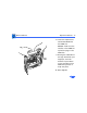
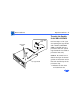
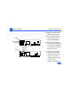
13 Remove the two Phillips
screws that secure the
fence to the solder side
of the logic board.
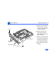
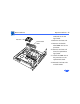
14 Remove the two hex
nuts that secure the
logic board fence to the
SCSI connector.
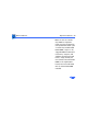
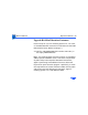
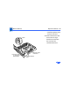
15 Remove the logic board
fence from the old logic
board and reinstall it on
the replacement board.
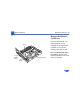
16 Plug in the logic board
battery.
Logic Board
Fence
Extended
Hex Nuts
Phillip Screws