K Service Source Power Macintosh 7200 Series/WS 7250 Power Macintosh 7200/75, 7200/90, 7200/120 and WS 7250/120
K Service Source Basics Power Macintosh 7200 Series/ WS 7250
Basics Overview - 1 Overview The chassis design of the Power Macintosh 7200 Series and WS 7250 computers allows you to access the logic board and its components without having to remove the power supply or any drives. This flexible design makes these computers easier to service and upgrade.
Basics Overview - 2 • AppleCD™ 600i or 1200i CD-ROM drive • CD-quality stereo sound in/out • Optional PC Compatibility Card (Power Macintosh 7200/120) • Mac™ OS system software 7.5.2 (7200/75 and 7200/90), system software7.5.3 (7200/120), and system software7.5.3 Revision 2 (7200/120 8x-CD) Note: VRAM expansion works as follows: 1 MB of VRAM is soldered to the board. To go to 2 MB, install one 1 MB VRAM DIMM in slot 1. To go to 4 MB, install three 1MB VRAM DIMMs in slots 1, 2, and 3.
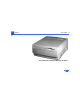
Basics Overview - 3 • Three PCI expansion slots • SCSI DMA bus that supports up to four external and three internal SCSI devices • Built-in AAUI and 10BASE-T Ethernet support • Support for AppleTalk and TCP/IP networking protocols • Two GeoPort serial ports • 1.2 GB or 2 GB hard drive • AppleCD™ 600i or 1200i CD-ROM drive • 16-bit stereo sound input/output • 1 MB of soldered VRAM • Mac™ OS system software 7.5.3 Revision 2 The Power Macintosh 7200 and WS 7250 computer is pictured on the following page.
Basics Overview - 4 Power Macintosh 7200 and WS 7250 Computer
Basics Configurations - 5 Configurations The Power Macintosh 7200 Series computers come standard with • • • • 75, 90, or 120 MHz PowerPC 601 microprocessor 8 or 16 MB DRAM 500 MB or 1.2 GB hard drive AppleCD 600i CD-ROM (7200/75, 7200/90, and 7200/120) or 1200i CD-ROM (7200/120 8x-CD) • 1 MB of VRAM soldered to the logic board The WS 7250/120 computer comes standard with • • • • • 120 MHz PowerPC 601 microprocessor 16 MB DRAM 1.
Basics PowerPC 601 Microprocessor - 6 PowerPC 601 Microprocessor The Power Macintosh 7200 Series and WS 7250 computers feature the PowerPC 601 RISC microprocessor.
Basics Peripheral Component Interconnect (PCI) - 7 Peripheral Component Interconnect (PCI) The Power Macintosh 7200 Series and WS 7250 computers offer a Peripheral Component Interconnect (PCI) expansion bus. Because the PCI bus is an industry standard, most existing PCI 2.0-compliant cards (with the addition of a Mac OS-specific software driver) will work in these computers. PCI offers significantly higher performance than the NuBus architecture used in previous Macintosh models.
Basics Dual In-Line Memory Modules (DIMMs) - 8 Dual In-Line Memory Modules (DIMMs) The Power Macintosh 7200 Series and WS 7250 computers use DRAM Dual In-Line Memory Modules (DIMMs) instead of DRAM SIMMs. Whereas SIMMs have 72 pins, DIMMs have 168 pins. The extra pins provide a 64-bit data path, compared to a 32-bit data path for SIMMs. In addition, DIMMs do not have to be installed in pairs like the SIMMs on earlier Macintosh models.
Basics Memory Configurations - 9 Memory Configurations The Power Macintosh 7200 and WS 7250 logic boards have four DRAM DIMM slots, each with a 64-bit data bus. You can increase the computer’s DRAM to a total of 256 MB using 5volt, 64-bit-wide, 168-pin fast-paged mode, 70 ns DIMMs. Note: These computers do not have any main memory soldered to the logic board. At least one DRAM DIMM must be present for the computer to operate. DRAM DIMMs can be installed individually or in pairs.
Basics Memory Configurations - 10 Note: DIMMs purchased from different manufacturers can be paired; However, Apple recommends that you use DIMMs of the same size and speed. The drawing on the next page illustrates where the DRAM slots are located on the Power Macintosh 7200 Series/WS 7250 logic boards and how they are numbered. DRAM can be installed in any order.
Basics Memory Configurations - 11 4 3 2 1 Figure: DRAM DIMM Slots
Basics Ethernet Support - 12 Ethernet Support There are two Ethernet ports on the Power Macintosh 7200 Series and WS 7250 logic boards: an AAUI port and a 10BASE-T port. You can use only one Ethernet port at one time, however. If you have cables plugged into both Ethernet ports, the computer uses the 10BASE-T port by default. GeoPort Geoport is a hardware and software communications architecture that has been optimized for computertelephony integration.
Basics GeoPort - 13 • Once connected, it supports an arbitrary number of independent data streams up to a total bandwidth of 2 MB/ second. • Unlike traditional asynchronous data communications (such as AppleTalk), GeoPort also supports isochronous data streams (such as real-time voice and video) and provides the real-time Application Program Interfaces (APIs) necessary to hide the implementation details from both the recipient and the sender.
Basics PC Compatibility Cards - 14 PC Compatibility Cards The Power Macintosh 7200/120 features an optional PC Compatibility card, which brings full DOS functionality to the Macintosh computer. Two versions of the PC Compatibility card are available: a 7" card and a 12" card. The cards plug into any available PCI slot on the logic board. The two PC Compatibility cards are also available in individual upgrade kits. Refer to the Upgrades chapter in this manual for installation instructions.
Basics The Cuda Chip - 15 The Cuda Chip The Cuda is a microcontroller chip. Its function is to • Turn system power on and off • Manage system resets from various commands • Maintain parameter RAM (PRAM) • Manage the Apple Desktop Bus (ADB) • Manage the real-time clock Many system problems can be resolved by resetting the Cuda chip (see Symptom Charts for examples). Press the Cuda reset button on the logic board to reset the Cuda chip.
Basics Resetting the Logic Board - 16 Resetting the Logic Board Resetting the logic board can resolve many system problems (refer to "Symptom Charts" for examples). Whenever you have a unit that fails to power up, you should follow this procedure before replacing any modules. 1 Unplug the computer. 3 Disconnect the power supply cable from the logic board and then press the Power On button. (See "Logic Board Diagram" later in this chapter to locate the Power On button.
Basics Resetting the Logic Board - 17 5 Reassemble the computer and test the unit. Note: This procedure resets the computer’s PRAM. Be sure to check the computer’s time/date and other system parameter settings afterwards. Note: If this procedure resolves the problem, claim an adjustment on an SRO. If not, replace the defective component and DO NOT claim the adjustment procedure.
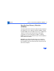
Basics Rear View Diagram - 18 Rear View Diagram The Power Macintosh 7200 Series and WS 7250 computers offer the following external ports: SCSI, AAUI Ethernet, 10BASE-T Ethernet, serial printer (GeoPort compatible), serial modem (GeoPort compatible), DB-15 video, ADB, sound input, and sound output. The drawing on the next page illustrates the external ports on the Power Macintosh 7200 Series and WS 7250 computers.
Basics Rear View Diagram - 19 Printer Sound Out Sound In SCSI ADB AAUI Ethernet Monitor Modem 10BASE-T Ethernet Figure: Power Macintosh 7200 and WS 7250 Rear Panel
Basics Power Macintosh 7200 Logic Board Diagram - 20 Power Macintosh 7200 Logic Board Diagram There are five versions of the Power Macintosh 7200 logic board: one 75 MHz version, two 90 MHz versions, and two 120 MHz versions. The two 90 MHz versions of the logic board are functionally equivalent, as are the two 120 MHz versions; However, one of the 90 MHz versions and one of the 120 MHz versions has an auxiliary fan that connects at J70.
Basics Power Macintosh 7200 Logic Board Diagram - 21 Internal Power SCSI Supply CD Floppy 3.
Basics Workgroup Server 7250 Logic Board Diagram - 22 Workgroup Server 7250 Logic Board Diagram There is only one version of the WS 7250 logic board, which features a 120 MHz microprocessor. This board does not require an auxiliary processor fan. The following drawing shows the WS 7250 logic board. Note: Some versions of the logic board have a ROM SIMM while others have the ROM soldered on the logic board.
Basics Workgroup Server 7250 Logic Board Diagram - 23 Internal Power SCSI Supply CD Floppy 3.
Basics Repair Strategy - 24 Repair Strategy Service the Power Macintosh 7200 Series and WS 7250 computers through module exchange and parts replacement. Customers can request on-site service from an Apple Authorized Service Provider Plus (AASP+) or Apple Assurance. They can also choose carry-in service from an AASP. Ordering Apple Service Providers planning to support the Power Macintosh 7200 Series and WS 7250 computers may purchase Service modules and parts to develop servicing capability.
Basics Ordering - 25 Large businesses, universities, and K-12 accounts must provide a purchase order on all transactions, including orders placed through the AppleOrder system. Service providers not enrolled in AppleOrder may fax their orders to Service Provider Support (512-908-8125) or mail them to Apple Computer, Inc. Service Provider Support MS 212-SPS Austin, TX 78714-9125 If you have further questions, please call Service Provider Support at 800-919-2775 and select option #1.
Basics Warranty and AppleCare - 26 Warranty and AppleCare The Power Macintosh 7200 Series and WS 7250 computers are covered under the Apple One-Year Limited Warranty. The AppleCare Service Plan is also available for these products. Service Providers are reimbursed for warranty and AppleCare repairs made to these computers. For pricing information, refer to "Service Price Pages.
K Service Source Specifications Power Macintosh 7200 Series/ WS 7250
Specifications Processor - 1 Processor CPU PM 7200/75 and 7200/90 PM 7200/120 and WS 7250/120 PowerPC 601 RISC microprocessor running at 75 or 90 MHz Built-in FPU and 32K cache Requires system software version 7.5.2 or later with appropriate System Enabler PowerPC 601 RISC microprocessor running at 120 MHz Built-in FPU and 32K cache Requires system software version 7.5.
Specifications Memory - 2 Memory DRAM 8 MB or 16 MB standard; expandable to 256 MB Uses 168-pin, 64-bit, 70 ns or faster DRAM DIMMs ROM 4 MB ROM (may be installed in ROM SIMM slot, or soldered on the logic board) Cache Supports 256K Level 2 cache DIMM Clock/Calendar CMOS custom circuitry with long-life battery
Specifications I/O Interfaces - 3 I/O Interfaces SCSI Dual-channel asynchronous SCSI interface; external channel supports up to seven SCSI devices Serial Two RS-232/RS-422 serial ports compatible with LocalTalk and GeoPort cables; mini DIN-8 connectors ADB One Apple Desktop Bus port for a keyboard, mouse, etc.
Specifications Expansion I/O Interfaces - 4 Three PCI expansion slots, compatible with all PCI 2.
Specifications I/O Devices - 5 I/O Devices Keyboard Standard, extended, or adjustable keyboard; keyboard draws 25-80 mA, depending on model type Mouse ADB Mouse II; mouse draws up to 10 mA Microphone PM 7200 Series Apple PlainTalk microphone standard
Specifications Video Support - 6 Video Support Table 1: Video Table for Power Macintosh 7200 Series/WS 7250 PIXEL DEPTHS MONITOR DISPLAY SIZE 512 by 384 640 by 480 768 by 576 800 by 600 832 by 624 1024 by 768 1280 by 960 1280 by 1024 1 MB VRAM* 8,16,32 8,16 8,16 8,16 8,16 8 _ _ 2 MB VRAM* 8,16,32 8,16,32 8,16,32 8,16,32 8,16,32 8,16 8 8 4 MB VRAM* 8,16,32 8,16,32 8,16,32 8,16,32 8,16,32 8,16,32 8,16 8,16 *VRAM expansion works as follows:1 MB of VRAM is soldered to the board.
Specifications Disk Storage - 7 Disk Storage Hard Drive PM 7200/75 and 7200/90 500 MB internal SCSI hard drive PM 7200/120 1.2 GB internal SCSI hard drive WS 7250/120 2 GB internal SCSI hard drive Floppy Drive One Apple SuperDrive 1.
Specifications PC Compatibility Card (Optional) - 8 PC Compatibility Card (Optional) Processor 7" Card 12" Card 5x86 processor operating at 100 MHz Pentium processor operating at 100 MHz DRAM 7" Card 12" Card 8 MB DIMM standard, expandable to 64 MB 8 MB built-in, expandable to 72 MB VRAM 7" Card 12" Card 1 MB 1 MB, expandable to 2 MB
Specifications PC Compatibility Card (Optional) - 9 Cache 7" Card 12" Card 128K Level 2 cache 256 K Level 2 Cache Sound Sound Blaster 16-compatible support Software MS-DOS version 6.
Specifications Electrical - 10 Electrical Line Voltage PM 7200 100-240 VAC, RMS single phase, automatically configured WS 7250/120 100-270 VAC, RMS single phase, automatically configured Frequency 50-60 Hz, single phase Maximum Power 150 W maximum, not including monitor Note: the power supply has two voltage settings: 115V and 230 V. The power supply must be set to 115V in the U.S.
Specifications Physical - 11 Physical Dimensions Height Width Depth Weight 6.5 in. (15.6 cm) 14.37 in. (36.5 cm) 16.93 in. (43.0 cm) 22 lb. (9.
Specifications Environmental - 12 Environmental Operating Temperature 50 to 104° F (10 to 40° C) Storage Temperature —40 to 116° F (—40 to 47° C) Relative Humidity 5% to 95% noncondensing Maximum Altitude 10,000 ft.
K Service Source Troubleshooting Power Macintosh 7200 Series/ WS 7250
Troubleshooting General - 1 General The Symptom Charts included in this chapter will help you diagnose specific symptoms related to your product. Because cures are listed on the charts in the order of most likely solution, try the first cure first. Verify whether or not the product continues to exhibit the symptom. If the symptom persists, try the next cure. (Note: If you have replaced a module, reinstall the original module before you proceed to the next cure.
Troubleshooting Cleaning Procedure for Card Connectors - 2 Cleaning Procedure for Card Connectors It is possible for residue to build up on the gold edge connector pins on some PCI cards, which could cause a variety of symptoms. If you are having problems with a PCI card, inspect the connector pins with a magnifying glass. If you find residue, use a pencil eraser to gently clean the pins.
Troubleshooting Symptom Charts/Power Supply - 3 Symptom Charts Power Supply System doesn’t power up 1 2 3 4 5 Reseat ROM SIMM (if present). Reset Cuda chip. (Refer to The Cuda Chip in Basics for instructions.) Reset logic board. (Refer to Resetting the Logic Board in Basics for instructions.) Replace power supply. Replace logic board.
Troubleshooting Symptom Charts/Error Chords - 4 Error Chords One-part error chord sounds during startup sequence 1 2 3 Eight-part error chord (death chimes) sounds during startup sequence 1 2 Disconnect SCSI data cable from hard drive and reboot system. If startup sequence is normal, initialize hard drive. Test unit again with SCSI data cable connected. If error chord still sounds, replace hard drive. Disconnect floppy drive cable from floppy drive and reboot system.
Troubleshooting Symptom Charts/System - 5 System Does not power on, screen is black, fan is not running and LED is not lit 1 2 3 4 5 6 7 8 Check power cables. Plug monitor directly into wall socket, and verify that monitor has power. Reseat ROM SIMM (if present). Reset Cuda chip. (Refer to The Cuda Chip in Basics for instructions.) Reset logic board. (Refer to Resetting the Logic Board in Basics for instructions.) Replace power cord. Replace power supply. Replace logic board. Retain customer's DIMMs.
Troubleshooting Clicking, chirping, or thumping Symptom Charts/System - 6 1 2 3 4 5 6 Remove all PCI cards and test the unit. If problem does not occur with cards removed, begin replacing them one at a time to determine which card is causing the problem. Replace problem card with known-good card. Remove hard drive. If problem no longer occurs, replace hard drive with a known-good drive. Replace power supply. Replace logic board. Retain customer's DIMMs. Replace floppy drive cable. Replace floppy drive.
Troubleshooting System shuts down intermittently Symptom Charts/System - 7 1 2 3 4 5 6 7 8 9 Make sure air vents are clear. Thermal protection circuitry may shut down system. After 30 to 40 minutes, system should be OK. Make sure power cord is firmly plugged in. Verify fan is plugged in and working (if present). Replace if necessary. (Note: Some 90 MHz versions of the Power Macintosh 7200 logic board have a fan that plugs into the logic board near the processor.) Replace power cord. Check battery.
Troubleshooting System intermittently crashes or hangs Symptom Charts/System - 8 1 2 3 4 5 6 7 Verify system software is version 7.5.2 or later (Power Macintosh 7200/75 or 7200/90) or 7.5.3 or later (Power Macintosh 7200/120 or WS 7250/120). Verify DIMMs are noncomposite. Verify software is known-good. Do a clean install of the system software. Verify software is Power Macintosh 7200/WS 7250 compatible (contact developer).
Troubleshooting Symptom Charts/System - 9 During startup, following message is displayed, "This startup disk will not work on this Macintosh model...." 1 2 System can’t be powered off unless external 1.2 GB hard drive is off or LED remains lit when system is powered off and attached 1.
Troubleshooting Symptom Charts/System - 10 2) Disconnect hard drive SCSI cable and power cable. 3) Remove hard drive from chassis. 4) Turn drive over and examine part number label on 50-pin SCSI connector (removing drive carrier if necessary). If label reads “1280S p/n TM12S012” and “REV 02-B”, replace drive. Note: Only Revision “02” drives cause this problem; therefore, make sure bar code label includes the words “REV 02B” before replacing hard drive.
Troubleshooting Symptom Charts/Video - 11 Video Screen is black, boot tone is present, drive operates, fan is running, and LED is lit 1 2 3 4 5 6 7 8 Adjust brightness on monitor. Clear parameter RAM. Hold down
Troubleshooting Screen is black, no boot tone and drive does not operate, but fan is running and LED is lit Symptom Charts/Video - 12 1 2 3 4 5 Reset Cuda chip. (Refer to The Cuda Chip in Basics for instructions.) Reset logic board. (Refer to Resetting the Logic Board in Basics for instructions.) Remove all DRAM DIMMs and try replacing them one at a time to test. Replace any bad DIMMs. Replace logic board. Retain customer's DIMMs. Replace power supply.
Troubleshooting Boot tone is present and screen lights up, but nothing is displayed on screen Symptom Charts/Video - 13 1 2 3 4 5 Reset Cuda chip. (Refer to The Cuda Chip in Basics for instructions.) Reset logic board. (Refer to Resetting the Logic Board in Basics for instructions.) Replace monitor cable. Test with known-good monitor. Replace monitor if necessary. Refer to appropriate monitor manual to troubleshoot defective monitor. Replace logic board. Retain customer's DIMMs.
Troubleshooting Symptom Charts/Floppy Drive - 14 Floppy Drive Internal floppy drive does not operate 1 2 3 4 Replace floppy disk with known-good disk. Replace floppy drive cable. Replace floppy drive. Replace logic board. Retain customer's DIMMs. During system startup, disk ejects; display shows icon with blinking “X” 1 2 3 4 Replace disk with known-good system disk. Replace floppy drive cable. Replace floppy drive. Replace logic board. Retain customer's DIMMs.
Troubleshooting Does not eject disk Symptom Charts/Floppy Drive - 15 1 2 3 4 Attempts to eject disk, but doesn’t 1 2 Shut down computer. Hold mouse button down while you restart computer. Replace floppy drive cable. Replace floppy drive. Replace logic board. Retain customer's DIMMs. Reseat floppy drive bezel and drive so bezel slot aligns correctly with drive. Replace floppy drive.
Troubleshooting Symptom Charts/Floppy Drive - 16 MS-DOS drive does not recognize a disk formatted on a 1.4 MB drive To read and write files with either MS-DOS or 1.4 MB drive, format all disks with MS-DOS drive first. Internal floppy drive runs continuously 1 2 3 4 Replace disk with known-good floppy disk. Replace floppy drive cable. Replace floppy drive. Replace logic board. Retain customer's DIMMs.
Troubleshooting Symptom Charts/Hard Drive - 17 Hard Drive Single internal hard drive does not operate; drive doesn’t spin 1 No internal SCSI drives operate 1 2 2 3 4 5 Replace hard drive. If problem resolved, reinstall SCSI device driver and system software. Replace power supply. Verify there are no duplicate SCSI device addresses. Disconnect external SCSI devices and check for proper termination. Only last device in SCSI chain should be terminated. Replace SCSI data cable. Replace power supply.
Troubleshooting Drive does not appear on the desktop Symptom Charts/Peripherals - 18 1 2 3 4 5 6 Works with internal or external SCSI devices but not with both 1 2 3 4 Verify there are no duplicate SCSI device addresses. Update SCSI device driver using Drive Setup. Check drive’s directory structure using Disk First Aid. Replace SCSI hard drive cable. If drive is not initialized, use Drive Setup to initialize. Replace with known-good hard drive.
Troubleshooting Symptom Charts/Peripherals - 19 Peripherals Cursor does not move 1 2 6 Check mouse connection. Inspect inside of mouse for buildup of dirt or other contaminants. Clean mouse if necessary. If mouse was connected to keyboard, connect mouse to computer ADB port instead. If mouse works, replace keyboard. Replace ADB cable. If mouse does not work in any ADB port on computer, replace mouse. Replace logic board. Retain customer's DIMMs. 1 2 3 Boot from floppy or bootable CD. Replace mouse.
Troubleshooting Double-click doesn’t open application, disk, or server Symptom Charts/Peripherals - 20 1 2 5 Remove duplicate system folders. Clear parameter RAM. Hold down
Troubleshooting Symptom Charts/Peripherals - 21 Known-good serial printer does not work 1 2 3 4 5 6 Verify you have correct version of system software. Verify that Chooser is set correctly. Reinstall correct printer drivers. Do clean install of system software. Replace printer interface cable. Replace logic board. Retain customer's DIMMs. Known-good network printer does not print 1 2 3 4 Check network connections. Verify you have correct version of system software.
Troubleshooting Symptom Charts/CD-ROM Drive - 22 CD-ROM Drive CD-ROM drive does not work 1 2 Try using known-good compact disc. Replace CD-ROM drive mechanism. Macintosh does not display CD-ROM icon once CD is inserted in drive 1 2 3 Verify that CD-ROM software is installed. Replace CD-ROM drive mechanism. Replace SCSI data cable. Computer with 600i CD-ROM drive makes stuttering sounds when playing CD+ or CD-R formatted discs or CD-ROM disc won’t mount Replace CD-ROM drive.
Troubleshooting Symptom Charts/Miscellaneous - 23 Miscellaneous No sound from speaker 1 2 3 4 5 Verify that volume setting in Control Panel is 1 or above. Clear parameter RAM. Hold down
Troubleshooting Transferring/printing large files across certain repeaters causes Power Macintosh 7200/90 to hang or exhibit poor performance or Power Macintosh 7200/90 locks up or times out when running under TCP Symptom Charts/Miscellaneous - 24 1 2 Verify computer is Power Macintosh 7200/90 and attached to Ethernet network. Test to see if problem occurs on other systems (preferably Power Macintosh 7200/75, 7500, 8500, or 9500 computers that utilize the new Open Transport networking protocol).
Troubleshooting Symptom Charts/Miscellaneous - 25 Identifying Logic Boards As a general rule, if the Power Macintosh 7200/90 computer has a serial number of xx545xxxxxx or higher, then the computer should have the revised logic board already installed. If the computer has a serial number of xx544xxxxxx, xx543xxxxxx or below, verify that the board is revised as follows: Look at location G1; G1 is located next to the internal 50-pin SCSI connector and the CURIO ASIC.
K Service Source Take Apart Power Macintosh 7200 Series/ WS 7250
Take Apart Top Housing Top Housing - 1 Top Housing No preliminary steps are required before you begin this procedure. Note: The top housing covers the top, front, and left and right sides of the computer.
Take Apart Top Housing - 2 1 Left Tab Right Tab Press the two tabs at the front corners of the top housing to release the top housing from the bottom chassis.
Take Apart Top Housing - 3 2 Pull the top housing forward about 1 to 2 inches and lift straight up to remove the top housing from the computer.
Take Apart Bezels - 4 Bezels Before you begin, remove the top housing. Note: As you face the computer, the bezels are in the middle of the top housing’s front panel.
Take Apart Bezels - 5 Tab 1 From the inside of the top housing, push out on the moon-shaped opening at the bottom of the bezel to release the tab. Lift up the bezel to remove it from the top housing.
Take Apart CD-ROM Drive - 6 CD-ROM Drive Before you begin, remove the top housing. Note: As you face the computer, the CD-ROM drive is in the bottom right drive bay.
Take Apart CD-ROM Drive - 7 1 CD-ROM Shield Lift up the top tabs and pull out the CD-ROM EMI shield to remove it from the front of the CD-ROM drive.
Take Apart CD-ROM Drive - 8 2 Power Cable SCSI Cable CD Audio Cable Disconnect the SCSI cable, power cable, and CD audio cable from the back of the CD-ROM drive.
Take Apart CD-ROM Drive - 9 3 Pull up the retaining clip (which is located at the back of the CD-ROM drive) and slide the CDROM forward to remove it from the internal chassis. Note: Be sure to remove the CD-ROM drive from its carrier before returning the drive to Apple.
Take Apart Floppy Drive - 10 Floppy Drive Before you begin, remove the top housing. Note: As you face the computer, the floppy drive is in the top right drive bay.
Take Apart Floppy Drive - 11 1 Floppy Drive Shield Blank Shield CD-ROM Shield Remove the CD-ROM shield, the blank shield, and the floppy drive shield from the front of the unit.
Take Apart Floppy Drive - 12 Chassis Support Foot 2 Flip open the chassis support foot.
Take Apart Floppy Drive Cable Floppy Drive - 13 Floppy Drive 3 Disconnect the floppy drive cable from the back of the floppy drive.
Take Apart Drive Rails Floppy Drive - 14 Floppy Drive 4 Pull out on the plastic drive rails that hold the floppy drive to the drive chassis and push the drive back to release it. Replacement Note: If you are replacing the floppy drive, remove the EMI gasket from the defective drive and attach the gasket in the center of the replacement drive’s top surface, with the “V” of the gasket pointing at the front edge of the drive. If the old gasket won't stick, order a new gasket (p/n 922-1895).
Take Apart Hard Drive - 15 Hard Drive Before you begin, remove the top housing. Note: As you face the computer, the hard drive is in the top left drive bay.
Take Apart Hard Drive - 16 1 Floppy Drive Shield Blank Shield CD-ROM Shield Remove the CD-ROM shield, the blank shield, and the floppy drive shield from the front of the unit.
Take Apart Hard Drive - 17 2 Power Cable SCSI Cable Disconnect the SCSI cable and hard drive power cable from the back of the hard drive.
Take Apart Hard Drive - 18 3 Retaining Clip Pull up the retaining clip at the back of the hard drive and push back the hard drive to remove it from the drive chassis. Note: For information on removing the hard drive from its carrier and returning drives, cables, and carriers to Apple, refer to Additional Procedures in the Hard Drives manual.
Take Apart Chassis Latch - 19 Chassis Latch Chassis Latch Before you begin, remove the top housing. Note: The chassis latches mount in the internal chassis and secure the internal chassis to the external chassis frame.
Take Apart Chassis Latch - 20 1 Tab Use a screwdriver to push out the tab indicated in the illustration. Slide the latch forward and lift it from the chassis.
Take Apart Drive Rails - 21 Drive Rails Before you begin, remove: • Top Housing • All Drives Note: The drive rails attach to the internal chassis underneath the CD-ROM drive and the extra hard drive bay.
Take Apart Drive Rails - 22 1 Internal Chassis Chassis Support Foot First, release the chassis latches. Next, flip open the chassis support foot and then swing open the internal chassis that contains the power supply. IMPORTANT: On some 90 and 120 MHz versions there is a fan that plugs into the logic board at connector J70. You must unplug the fan as you are swinging open the chassis. Be sure to plug the fan back in when you put the unit back together.
Take Apart Drive Rails - 23 Tab 2 3 Use a screwdriver to push out the tab indicated in the illustration. Slide the drive rail either forward or backward (depending on which way the tabs are facing) and lift it from the chassis. IMPORTANT: On some 90 and 120 MHz versions there is a fan that plugs into the logic board at connector J70. Be sure to plug the fan back in when you put the unit back together.
Take Apart Battery - 24 Battery Before you begin, remove the top housing. Note: As you face the computer, the battery is near the front left corner of the logic board.
Take Apart Battery - 25 1 Internal Chassis Chassis Support Foot First, release the chassis latches. Next, flip open the chassis support foot and then swing open the internal chassis that contains the power supply. IMPORTANT: On some 90 and 120 MHz versions there is a fan that plugs into the logic board at connector J70. You must unplug the fan as you are swinging open the chassis. Be sure to plug the fan back in when you put the unit back together.
Take Apart Battery - 26 2 Use a screwdriver to gently pry up one side of the battery cover.
Take Apart Battery - 27 3 Lift up the battery to remove it from the logic board. IMPORTANT: On some 90 and 120 MHz versions there is a fan that plugs into the logic board at connector J70. Be sure to plug the fan back in when you put the unit back together.
Take Apart Power Supply - 28 Power Supply Power Supply Before you begin, remove the top housing. Note: As you face the computer, the power supply is in the back right corner. IMPORTANT: When replacing the power supply, be sure the voltage switch on the back of the power supply is set correctly (115V in the U.S.).
Take Apart Hard Drive Power Cable Power Supply - 29 CD Power Cable 1 Disconnect the power supply cables from the back of the CD-ROM drive and hard drive(s).
Take Apart Power Supply - 30 2 Internal Chassis Chassis Support Foot First, release the chassis latches. Next, flip open the chassis support foot and then swing open the internal chassis that contains the power supply. IMPORTANT: On some 90 and 120 MHz versions there is a fan that plugs into the logic board at connector J70. You must unplug the fan as you are swinging open the chassis. Be sure to plug the fan back in when you put the unit back together.
Take Apart Power Supply - 31 3 Chassis Support Arm To secure the internal chassis in the up position, flip down the chassis support arm. Make sure the tab on the bottom of the support arm is securely fastened in the hole provided in the bottom chassis. Warning: To be safe, never work on the computer with the internal chassis in the up position unless the chassis support arm is down and securely fastened.
Take Apart Power Supply - 32 Power Supply Cables 4 Disconnect the power supply cables from the logic board. Note: The 22-pin cable supplies 5 V and +/- 12 V power for the logic board.
Take Apart Screw Screw Power Supply - 33 5 From the back of the computer, remove the two screws that secure the power supply to the chassis.
Take Apart Power Supply - 34 6 Chassis Support Arm Tab Release the chassis support arm and swing down the internal chassis. IMPORTANT: On some 90 and 120 MHz versions there is a fan that plugs into the logic board at connector J70. Be sure to plug the fan back in when you put the unit back together.
Take Apart Power Supply - 35 7 Slide the power supply forward and pull it out of the computer. You will need to feed the power supply cables that connect to the logic board up through the hole in the chassis. IMPORTANT: Make sure the power supply switch on the back of the power supply is set to the correct voltage (115V in the U.S.) The switch is accessible through the computer’s rear panel when the power supply is installed.
Take Apart Power Supply - 36 Replacement Note: There are two metal tabs on the back of the metal chassis that lock into the power supply. When replacing the power supply, slide it back until it locks into place.
Take Apart Speaker - 37 Speaker Before you begin, remove the top housing. Speaker Note: As you face the computer, the speaker is in the front left corner of the bottom chassis.
Take Apart Speaker - 38 1 Swing open the expansion card cover.
Take Apart Speaker - 39 2 Screw Screw Remove the two Torx screws that secure the speaker to the metal chassis.
Take Apart Speaker - 40 3 4 Speaker Cable Latch Disconnect the speaker cable from the logic board. Press the latch holding the speaker to the chassis and lift the speaker out of the computer.
Take Apart Power Actuator - 41 Power Actuator Before you begin, remove the top housing. Note: As you face the computer, the power actuator is in the front left corner of the bottom chassis (directly beneath the speaker).
Take Apart Power Actuator - 42 1 Tab Power Actuator Push in the tab that secures the power actuator to the chassis and push the power actuator out of the computer.
Take Apart PCI Covers - 43 PCI Covers Before you begin, remove the top housing. Note: As you face the back of the computer, the PCI covers are on the right side of the rear panel.
Take Apart PCI Covers - 44 1 Swing open the expansion card cover.
Take Apart PCI Covers - 45 2 PCI Cover From the back of the computer, press in and lift up on the PCI cover to remove it.
Take Apart Rear Panel - 46 Rear Panel Before you begin, remove the top housing. Note: The rear panel covers the back side of the computer through which all the external connectors are accessible.
Take Apart Rear Panel - 47 1 Internal Chassis Chassis Support Foot First, release the chassis latches. Next, flip open the chassis support foot and then swing open the internal chassis that contains the power supply. IMPORTANT: On some 90 and 120 MHz versions there is a fan that plugs into the logic board at connector J70. You must unplug the fan as you are swinging open the chassis. Be sure to plug the fan back in when you put the unit back together.
Take Apart Tab Rear Panel - 48 2 Lift the rear panel straight up to unhook it from the chassis. Once the rear panel is unhooked, you can remove it from the computer. Note: There are tabs on the rear panel that hook into the metal chassis. IMPORTANT: On some 90 and 120 MHz versions there is a fan that plugs into the logic board at J70. Be sure to plug the fan back in when you put the unit back together.
Take Apart Rear Panel - 49 Replacement Note: To replace the rear panel, you must first follow the procedures for removing the logic board. Instead of fully removing the logic board from the chassis, however, just slide it forward about an inch. Once you have the rear panel in place, slide the logic board back toward the rear panel until the board locks into place. Be sure the logic board connectors are lined up properly with the openings in the rear panel.
Take Apart PCI Card PCI Cards - 50 PCI Cards Before you begin, remove the top housing. Note: PCI expansion cards, if present, install perpendicularly to the logic board in one of three PCI slots. They are located directly beneath the plastic PCI guide. If installing third-party PCI cards, use the middle PCI slot for better clearance with the expansion card cover. If necessary, remove the expansion card cover.
Take Apart PCI Cards - 51 1 Swing open the expansion card cover to provide access to the logic board.
Take Apart PCI Cards - 52 2 PCI Card Grab the corners of the PCI card and pull up the card to remove it. Replacement Note: When installing third-party PCI cards, use the middle PCI slot for better clearance with the expansion card cover. If the expansion card cover will not close completely once the thirdparty card is installed, remove the expansion card cover. Be sure to check for proper clearance when replacing the computer's top housing.
Take Apart VRAM DIMMs - 53 VRAM DIMMs Before you begin, remove the top housing. Note: VRAM DIMMs install in the VRAM DIMM slots on the logic board. VRAM DIMM Slots Note: The Power Macintosh 7200 Series and WS 7250 computers use VRAM DIMMs (112-pin,70 ns or faster) instead of VRAM SIMMs. The VRAM SIMMs used in earlier Power Macintosh models are not compatible.
Take Apart VRAM DIMMs - 54 1 Internal Chassis Chassis Support Foot First, release the chassis latches. Next, flip open the chassis support foot and then swing open the internal chassis that contains the power supply. IMPORTANT: On some 90 and 120 MHz versions there is a fan that plugs into the logic board at connector J70. You must unplug the fan as you are swinging open the chassis. Be sure to plug the fan back in when you put the unit back together.
Take Apart VRAM DIMMs - 55 2 Chassis Support Arm Tab To secure the internal chassis in the up position, flip down the chassis support arm and make sure its bottom tab is securely fastened in the hole provided in the bottom chassis. Warning: To be safe, never work on the computer with the internal chassis in the up position unless the chassis support arm is down and securely fastened.
Take Apart VRAM DIMMs - 56 3 Push down the release latch next to the VRAM DIMM. Grab the DIMM by the top corners and lift straight up to remove the DIMM. Note: See the following pages for important replacement information.
Take Apart VRAM DIMMs - 57 Replacement Note: Position the DIMM evenly over the slot and press down gently to install it. The release latch should click into place. Do not force the DIMM or you may damage it. Make sure the DIMM is evenly seated. Note: These computers use VRAM DIMMs (112-pin, 70 ns or faster) instead of VRAM SIMMs. The VRAM SIMMs used in earlier Power Macintosh models are not compatible. Note: 1 MB of VRAM is soldered to the board. To go to 2 MB, install one 1 MB VRAM DIMM in slot 1.
Take Apart VRAM DIMMs - 58 4 Chassis Support Arm Tab Be sure to release the chassis support arm before you swing down the internal chassis. IMPORTANT: On some 90 and 120 MHz versions there is a fan that plugs into the logic board at connector J70. Be sure to plug the fan back in when you put the unit back together.
Take Apart Logic Board - 59 Logic Board Before you begin, remove the following: • Top Housing • PCI Cards (if present) • Speaker • Power Actuator Note: The logic board is located in the very bottom of the bottom chassis.
Take Apart Logic Board - 60 1 Swing open the expansion card cover to provide access to the logic board.
Take Apart Logic Board - 61 2 Internal Chassis Chassis Support Foot First, release the chassis latches. Next, flip open the chassis support foot and then swing open the internal chassis that contains the power supply. IMPORTANT: On some 90 and 120 MHz versions there is a fan that plugs into the logic board at connector J70. You must unplug the fan as you are swinging open the chassis. Be sure to plug the fan back in when you put the unit back together.
Take Apart Logic Board - 62 22-Pin Power Supply CD Audio SCSI Floppy 10-Pin Power Supply 3 Disconnect the following cables from the logic board: both power supply cables, floppy drive cable, SCSI cable, and CD audio cable.
Take Apart Logic Board - 63 4 LED Cable Speaker Cable Disconnect the LED and speaker cables from the logic board.
Take Apart Logic Board - 64 5 Top Column Support Remove the screw inside the top column support that secures the logic board to the chassis.
Take Apart Logic Board - 65 6 Tab Tab Press down on the two tabs at the front of the logic board and slide the board forward (away from the rear panel) to release it from the tabs on the bottom chassis. Lift the logic board from the chassis to remove it. IMPORTANT: Remove the EMI clip when you take the logic board out of the chassis. Failure to comply may result in damage to the board. (See the next page for instructions).
Take Apart Logic Board - 66 7 Lift up the top edge of the EMI clip and pull it off the board to remove it. IMPORTANT: Some 90 and 120 MHz versions have a fan that plugs into the logic board at J70. Be sure to plug the fan back in when you put the unit back together. EMI Clip Note: Remove the EMI clip and any cache, DRAM, or VRAM DIMM(s) before returning the logic board to Apple. Do NOT remove the ROM SIMM (if present).
Take Apart Processor Fan - 67 Processor Fan Before you begin, remove the top housing. IMPORTANT: Only some versions of the 90 and 120 MHz logic board use the processor fan. If you replace the processor fan, make sure you plug it back into the logic board before you replace the top housing.
Take Apart Processor Fan - 68 1 Fan Connector Unplug the fan connector from the logic board.
Take Apart Processor Fan - 69 2 Internal Chassis Chassis Support Foot First, release the chassis latches. Next, flip open the chassis support foot and then swing open the internal chassis that contains the power supply.
Take Apart Processor Fan - 70 Screws 3 Remove the two screws that attach the processor fan to the internal chassis. Replacement Note: The processor fan installs at an angle so that it blows down directly on the processor when the internal chassis is closed.
Take Apart Processor Fan - 71 Replacement Note: Be sure to plug the processor fan connector back into the logic board.
Take Apart Bottom Chassis - 72 Bottom Chassis Before you begin, remove: • Top Housing • PCI Cards (if present) • AV Module • Speaker • Power Supply • Power Actuator • All Drives • Chassis Latches • Drive Rails • Logic Board • Rear Panel • Fan (if present)
Take Apart Bottom Chassis - 73 Note: The bottom chassis is what is left once all other modules have been removed.
K Service Source Upgrades Power Macintosh 7200 Series/ WS 7250
Upgrades PC Compatibility Cards - 1 PC Compatibility Cards There are three Apple PC Compatibility cards that can be installed in the Power Macintosh 7200 Series computers: • 7” 100 MHz PC Compatibility Card • 12” 100 MHz PC Compatibility Card • 12” 166 MHz-P PC Compatibility Card For more information about these cards and installation instructions, refer to the PC Compatibility Card manual on this Service Source CD.
Upgrades Power Macintosh 7600 Upgrade - 2 Power Macintosh 7600 Upgrade The Power Macintosh 7600 Upgrade kit includes: • A Power Macintosh 7600 logic board • An EMI clip and EMI gasket • An AV module connector assembly • A video out cover • Two M 2.5x88mm screws • A Power Macintosh 7600 product ID label Note: Unlike the Power Macintosh 7200, the Power Macintosh 7600 logic board does not have a built-in processor. You must install a separate processor card.
Upgrades Power Macintosh 7600 Upgrade - 3 Before you begin, remove the following components. Refer to the Take Apart chapter in this manual for instructions. • • • • • • • • Top Housing Processor Fan (if present) PCI Cards (if present) Speaker Power Actuator Cache DIMM DRAM DIMMs VRAM DIMMs Note: Set the Cache, DRAM, and VRAM DIMMs aside as you will be installing them on the Power Macintosh 7600 logic board in a later step.
Upgrades Power Macintosh 7600 Upgrade - 4 1 Remove the Power Macintosh 7200 logic board. (Refer to the Take Apart chapter for instructions.) IMPORTANT: When you take the Power Macintosh 7200 logic board out of the chassis, remove the EMI clip or you may damage the board. The EMI clip is located next to the sound in and out ports. EMI Clip Note: Do NOT remove the ROM SIMM (if present) from the old logic board.
Upgrades Power Macintosh 7600 Upgrade - 5 2 Install the EMI gasket between the sound in and sound out ports on the Power Macintosh 7600 logic board. Note: The gasket may already be installed. Be sure to check.
Upgrades Power Macintosh 7600 Upgrade - 6 3 4 5 Install the EMI clip that came with the Upgrade Kit onto the Power Macintosh 7600 logic board in the same location as the one you removed from the old logic board at the very beginning of the upgrade procedure. IMPORTANT: Once you have installed the EMI clip, do not set down the logic board or you may damage the board. Be sure to install the logic board into the bottom housing immediately. Install the logic board in the computer.
Upgrades Power Macintosh 7600 Upgrade - 7 Note: For the next two steps, turn the computer so you are facing the inside of the rear panel. 6 Press in on the two plastic tabs at the bottom of the blank AV module cover, and push out on the cover to remove it. Note: Once the blank cover is removed, you will see a plastic frame with port holes for the AV module.
Upgrades Power Macintosh 7600 Upgrade - 8 7 Place the video out cover over the bottom two openings on the left side.
Upgrades Power Macintosh 7600 Upgrade - 9 8 9 From the inside of the computer, position the AV module into the plastic frame so that its connectors fit into the appropriate holes in the frame. Secure the AV module with the two screws that came in the Upgrade Kit. 10 Attach the AV module to the logic board. The AV connector on the logic board is located between the processor card slot and the first PCI slot.
Upgrades Power Macintosh 7600 Upgrade - 10 Processor Card Note: At this point you must install a processor card in the computer. The processor card is not included in the Power Macintosh 7600 Upgrade Kit and must be purchased separately. The processor card installs perpendicularly to the logic board directly beneath the plastic PCI guide. Note: If you install a 132 or 150 MHz card, you must also install an EMI grounding clip.
Upgrades Processor Card Power Macintosh 7600 Upgrade - 11 Heat Sink 11 Position the card evenly over the processor card slot and press down gently. Do not force the card or you may damage it. Make sure the card is seated evenly. Note: If the card is properly seated, the gold contacts on the card should not be visible.
Upgrades Power Macintosh 7600 Upgrade - 12 Grounding Clip Processor Card Heat Sink Top Chassis (Back of Computer) (L18) Installing grounding clip 12 If you are installing a 132 MHz card, be sure to install the EMI grounding clip that came with the 132 MHz Upgrade Kit.
Upgrades Power Macintosh 7600 Upgrade - 13 13 Replace the following components. Refer to the Take Apart chapter for instructions: • Power Actuator • Speaker • PCI Cards (if present) • Top Housing IMPORTANT: Do not replace the processor fan (if present in the original Power Macintosh 7200 unit). The fan is not used with the Power Macintosh 7600 logic board and will interfere with air flow and the installation of the processor card.
K Service Source Exploded View Power Macintosh 7200 Series/ WS 7250
Exploded View 1 Top Housing 922-1642 Power Supply 661-0920 SCSI Cable 922-1637 CD-ROM Bezel Blank Bezel 922-1649 922-1651 Hard Drive 661-0219 661-0228 Hard Drive Carrier 922-0621 Floppy Drive Cable 922-1636 Expansion Card Cover 922-1660 Fan 922-1736 (used With 661-0979) Floppy Drive 661-0121 Floppy/Hard Drive Chassis 922-1657 Blank AV Cover 922-1722 Floppy Drive Shield 922-1648 Blank PCI Cover 922-1628 Blank Shield 922-1652 Drive Rail 922-1658 Rear Panel 922-1655 Support Foot 922-1661 Support A
Exploded View 2 Top Housing 922-1642 Power Supply 661-0920 SCSI Cable 922-1637 CD-ROM Bezel Blank Bezel 922-1649 922-1651 Hard Drive 661-0180 661-1142 Hard Drive Carrier 922-0621 Floppy Drive Cable 922-1636 Floppy Drive 661-0121 Expansion Card Cover 922-1660 Floppy/Hard Drive Chassis 922-1657 Floppy Drive Shield 922-1648 Blank AV Cover 922-1722 Blank PCI Cover 922-1628 Blank Shield 922-1652 Drive Rail 922-1658 Rear Panel 922-1655 Support Foot 922-1661 Support Arm 922-1730 LED Cable 922-0841 Power