Xserve G5 User’s Guide Includes setup, expansion, and hardware specifications for Xserve G5
K Apple Computer, Inc. © 2004 Apple Computer, Inc. All rights reserved. Under the copyright laws, this manual may not be copied, in whole or in part, without the written consent of Apple. Your rights to the software are governed by the accompanying software license agreement. The Apple logo is a trademark of Apple Computer, Inc., registered in the U.S. and other countries.
1 Preface 7 Contents Introducing Xserve G5 Chapter 1 9 10 12 14 16 18 Xserve G5 Overview Your Server at a Glance—Front Panel Your Server at a Glance—Back Panel Your Server at a Glance—Interior Your Cluster Node Server at a Glance Your Server at a Glance—Mounting Hardware Chapter 2 21 21 21 22 23 23 23 24 Preparing to Install Your Server Guidelines for Server Installation Choose the Server’s Position in a Rack Electrical Power Operating Environment Rack Stability Considerations for Cables Security
58 4 58 59 59 59 60 60 60 61 62 63 Monitoring Status Lights and Other Indicators on the Server Working With Advanced Network Services Setting Up a Virtual Local Area Network (VLAN) Enabling Jumbo Ethernet Frames Controlling Access to a Connected Keyboard and Mouse Working With an Uninterruptible Power Supply (UPS) Changing the System Language Shutting Down the System Remotely If the Server Has a Problem What to Do If . . .
90 90 91 91 91 91 91 Protecting Your Optical Drive Power Supply Cleaning Your Equipment Cleaning the Server’s Case Apple and the Environment For More Information Health-Related Information About Computer Use Contents 5
Preface Introducing Xserve G5 Congratulations on purchasing your new server. This product is designed to be mounted in a rack. Once the server is installed in the rack, an administrator or other user can slide it open from the front to exchange or add components.
Among the services included with the Mac OS X Server standard configuration are: File and print services for Macintosh, Windows, and UNIX clients High-performance Apache web server, with integrated WebDAV and SSL World Wide Web application deployment platform QuickTime Streaming Server IP filtering, DHCP, DNS, and SLP networking services Directory services Mail service NetBoot server for Macintosh client computers that can start up from a server Tools for remote server configuration and monitoring • • • •
1 Xserve G5 Overview 1 This chapter introduces the key components of your Xserve G5 system. Both the fully configured server and the “cluster node” system are summarized here. The illustrations on the pages that follow provide a reference for the server. Depending on the configuration of your server, it may look slightly different from the illustrations shown here.
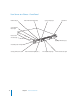
Your Server at a Glance—Front Panel FireWire 400 port Built-in Ethernet link light (Port 2) System activity lights Optical drive System identifier button/light Enclosure lock and status light Apple Drive Module bays (3) On/standby button and light Securing thumbscrews (2) 10 Built-in Ethernet link light (Port 1) Chapter 1 Xserve G5 Overview Drive module activity light Drive module status light
® On/standby button and light Press to turn on the server. Enclosure lock and lock status light The lock secures the enclosure and drive modules in the server. It can be locked and unlocked with the enclosure key supplied with the server. An option in the Security pane of System Preferences lets you inactivate a connected keyboard and mouse when the enclosure lock is engaged. This option is turned off by default. See “Controlling Access to a Connected Keyboard and Mouse” on page 59 for details.
Your Server at a Glance—Back Panel Power socket Ethernet link lights 12 Gigabit Ethernet port(s) System identifier button/light Ethernet activity lights FireWire 800 ports (2) Chapter 1 Xserve G5 Overview Serial console port PCI-X card expansion slots (2) USB 2.
≤ Power socket The power cord connects here; it is held in place by a special clip so that it stays connected when the server is opened in the rack. System identifier button and light The system identifier light turns on if a problem is detected. It also can be turned on manually by pressing the button. This indicator is useful for locating a particular unit in a rack with multiple servers. A duplicate system identifier button and light are on the front panel.
Your Server at a Glance—Interior PCI-X card slots (2) Battery Power supply RAM slots (8) Chassis release latch PCI fan Fan array Chassis release latch 14 Serial number label Chapter 1 Xserve G5 Overview
PCI-X card slots You can install two PCI-X or PCI expansion cards in the two expansion slots, which support 33, 66, 100, and 133 MHz cards. See “Installing a PCI-X Card or PCI Card” on page 78 for more information about installing cards. ECC DDR SDRAM expansion slots Expand your system’s memory up to 8 gigabytes (GB) with error-correcting (ECC), doubledata-rate memory. You can add memory by inserting DDR SDRAM DIMMs in pairs in the memory slots. For more information, see “Adding Memory” on page 75.
Your Cluster Node Server at a Glance Enclosure lock and status light System identifier button/light FireWire 400 port On/standby button and light System activity lights Securing thumbscrews (2) Drive module activity light 16 Built-in Ethernet link light (Port 2) Built-in Ethernet link light (Port 1) Apple Drive Module bay Chapter 1 Xserve G5 Overview Drive module status light
® On/standby button and light Press to turn on the server. Enclosure lock and lock status light The lock secures the enclosure and drive modules in the server. It can be locked and unlocked with the enclosure key supplied with the server. An option in the Security pane of System Preferences lets you inactivate a connected keyboard and mouse when the enclosure lock is engaged. This option is turned off by default. See “Controlling Access to a Connected Keyboard and Mouse” on page 59 for details.
Your Server at a Glance—Mounting Hardware Mounting template Four-post braces Two-post brackets Cage nuts (Metric) Short screws Cage nuts (English) Four-post brackets Short-rack brackets Attachment screws (Metric) 18 Attachment screws (English) Chapter 1 Xserve G5 Overview Enclosure key
Four-post brackets Two rivets on each bracket secure it to the brace and the server’s cover. Four-post braces These two long U-shaped pieces support the back of the server and attach it to the rack. Two-post brackets These two short L-shaped brackets attach to the sides of the server’s enclosure and to the rack. Short-rack brackets These two brackets attach the back of the server to a short rack, 24 or 26 inches deep.
2 Preparing to Install Your Server 2 Before you install the server in a rack, you should carefully consider the placement of the unit in its rack and several factors in the infrastructure that will keep the server operating efficiently. Guidelines for Server Installation To ensure safe and smooth operation of your server, it’s essential that you plan for proper location of the server in its rack, adequate power to the components in the rack, and the appropriate operating environment for the rack.
• To provide access to the server’s back panel and cables, leave at least 24 inches clear behind the server. • If you are installing multiple servers or other components in the rack, place the server so that you can easily open and service it. For example, in a multiplecomponent installation, the heaviest items—such as an uninterruptible power supply—are usually placed at or near the bottom of a rack; servers are often located near the middle of the rack.
Operating Environment The operating environment for the server’s rack must meet certain requirements: • Verify that the temperature range of the rack’s location is within the limits established for the server and all other components. • Make certain that the rack’s location has adequate ventilation to maintain the necessary temperature range. This is particularly important for a rack that is enclosed in a cabinet.
Security Whatever the location of the server and rack, it should be secure. • Make sure that only authorized staff members or technicians can gain access to the rack’s location. • If using a server cabinet that is not in a secure room, be sure that the cabinet is adequately locked and that access to it is limited to authorized staff. • Develop a plan for distributing and controlling keys to the server environment and access codes that allow others to manage servers over the network.
3 Installing Your Server in a Rack 3 This chapter shows you how to install the server in a rack. Xserve G5 is specifically designed for rack mounting. It is not designed for use as a desktop system. Warning: Do not place a monitor on the server or use the top of the server as a shelf in the rack. Any weight on the server’s enclosure could damage the components inside.
Getting Ready to Install As noted previously, you can install the server in a four-post rack of varying depth or a two-post rack. Instructions for these procedures are given below. Preparations for installing are the same regardless of the type of rack you use. Important: Check the documentation for your rack for any special requirements. Before beginning work with the server and rack, make the following preparations.
Determine the Position for the Server in the Rack Review the guidelines for positioning the server in the rack (see “Guidelines for Server Installation” on page 21). Then follow these steps to measure and mark its specific location. 1 Determine the exact position where you want to attach the server and mark it on one side of the rack. Some racks have marks at regular intervals (such as 1U) to aid in positioning a server; others may provide a template to help place the server in the rack.
Preparing the Server for Installation If possible, work with another person as you prepare and install the server in a rack. Follow these steps to prepare the server hardware for installation. 1 Unpack the server from its box and place it on the table. Follow the instructions in the booklet Xserve G5 Quick Start to unpack the server. 2 At the back of the server, write down the serial number from the server’s back panel.
Important: Keep the protector for the optical drive slot and put it in the drive’s slot whenever you move the system from one location to another or pack it for shipping. 6 Loosen the two thumbscrews (one on each side) at the front of the server’s enclosure. With the server resting on a flat, clean, and stable surface, unscrew the two thumbscrews on the front panel. These thumbscrews are “captive” and do not separate from the enclosure.
Hold the front thumbscrews to keep the main part of the server in place as you slide the cover toward the back. With the server resting on a flat, clean, and stable surface, slide the cover completely to the rear. Press these two latches to release the cover from the server and remove it. 8 When the cover is almost off, press the release latches at the sides of the server’s interior to release the cover, then take the cover off. When you’ve removed the cover, set it aside.
9 If necessary, install any optional internal components, such as additional memory or a PCI-X card, in the server. Follow the appropriate instructions in Chapter 6, “Installing or Replacing Server Components,” on page 69. PCI-X card slots (2) RAM slots (8) 10 If necessary, install any additional Apple Drive Modules in the front panel of the server. Follow the instructions in “Installing or Replacing an Apple Drive Module” on page 70.
When you’ve installed optional items, you’re ready to connect the server to the rack. If you have a four-post rack or cabinet that is 29–36 inches deep, proceed to “Installing the Server in a Four-Post Rack or Cabinet” on page 32. If you have a short rack that is 24 or 26 inches deep, go to “Installing the Server in a Short Four-Post Rack” on page 46. If you have a two-post rack, go to “Installing the Server in a Two-Post (Telco) Rack” on page 51.
Follow these steps to attach the server to the rack. 1 Keep the cover of the enclosure level and support it from the center as you slide it into the rack at the desired position. Important: Work with someone else to make sure the cover is supported and square to the rack. The cover must be installed level to avoid changing its shape before the screws are inserted to hold it in place. Have someone support the center of the cover while you attach it to the rack.
Be careful not to overtighten the flange screws. Doing so could change the shape of the cover. Take special care if you are using a power screwdriver or drill. Temporarily place the mounting template over the two posts on the cover. Attach the cover to the two front rack posts using four of the screws provided. Some racks have prethreaded holes and some have square holes that take clips with attached nuts. You may need to insert a clip into the appropriate hole before attaching the screw.
4 Push the rivet head through the hole that’s near the back on the side of the cover. Install the brackets on the inside of the top cover. The forward rivet on each bracket must pass through the hole in the cover. Each bracket must be installed with the rivets oriented high on the bracket. The head of the rivet protrudes through the cover. 5 Position the long, U-shaped brace on the outside of the server’s cover, so that the curved end is near the protruding rivet.
7 Slide the brace forward or backward so that the flat end of the brace is flush with the back post of the rack, and screw the brace’s flange to the post. Attach the cover to the two rear rack posts using four of the screws provided. 8 Attach the second bracket and brace, as described in steps 3 through 7. Note: If your rack is deeper than the server, the braces and brackets extend beyond the server’s back panel to the rack’s posts.
2 Secure the server in the rack by tightening the thumbscrews on the front. Important: Take care not to apply too much pressure on the thumbscrews if you use a power screwdriver or drill. The torque applied to the thumbscrews should not exceed 6.0 inch-pounds, and the rotation speed should not exceed 200 rpm. Tighten the two thumbscrews to secure the server in the rack. To secure the drive modules in the server, use the enclosure key to lock them in place. Remove the plastic optical drive protector.
Important: To open the server with the cables attached, you must install and use the cable-management arm. You can use the cable-management arm only with a four-post rack. If your rack is the same depth as the server (or an inch or so deeper), you attach the cable-management arm to the left rear post of the rack. If your rack is several inches deeper than the server, you attach the cable-management arm to the left brace that supports the back of the server.
The short part of the arm should be closer to the server’s back panel and the elongated holes on the long part of the arm should face the left back post of the rack (as you face the back of the server). Cable-management arm 4 Bunch together the cables and power cord and lay them along the cable-management arm, starting at the server side of the short part of the arm and moving to the side closer to you on the long side of the arm.
Moving the server forward allows you to check the position of the cable-management arm after you mount it. 2 Position the cable-management arm so that the short part is closer to the server’s back panel and the elongated holes on the long part align with the holes on the brace attached to the left post.
6 Connect the cables to the back panel of the server. Important: When connecting Ethernet cables, connect a cable to the lower Ethernet port (port 1) first. Ethernet port 2 2 Ethernet port 1 1 Link lights Activity lights If you connect only one Ethernet cable, make sure to connect it to port 1. Power socket Gigabit Ethernet ports (2) Serial console port FireWire 800 ports (2) USB 2.0 ports (2) 7 Connect the power cord and its retaining clip to the back of the server.
Note: You may need to bend the cord near its plug to fit it into the server. Bending the cord will not affect its operation. Attach the power cord retainer clip to the two loops on the back of the server. Snap the cord into the clip so that it cradles the cord. 8 Connect the other end of the cables to the appropriate devices. 9 Close the server and tighten the thumbscrews to secure it in the rack. 10 After all connections are complete, plug the power cord into a power source.
If the rear posts of your rack are flush with the server’s back panel or within an inch of it, see “Attach the Cable-Management Arm to the Rack” on page 39 for mounting instructions. Follow these steps to attach the arm to the left support brace. 1 At the front of the server, loosen the thumbscrews securing it to the rack and slide the server a few inches forward. Moving the server forward allows you to check the position of the cable-management arm after you mount it.
7 Verify that the arm’s position is correct by moving the arm inward so that it swings under the cover of the server. If the arm hits the cover or is not level as you move it, you need to adjust its position by unscrewing one or both mounting screws and moving the arm up or down slightly until it is level and moves smoothly under the server’s cover. 8 Connect the cables to the back panel of the server. Power socket Gigabit Ethernet ports (2) Serial console port FireWire 800 ports (2) USB 2.
9 Connect the power cord and its retaining clip to the back of the server. If more than one power cord came with your server, use the appropriate cord for the electrical service available at your location. Important: The short power cord provided with some systems is intended for use in a rack that has its own power source. Do not use this cord for any other purpose. Note: You may need to bend the cord near its plug to fit it into the server. Bending the cord will not affect its operation.
Installing the Server in a Short Four-Post Rack Some four-post racks are shorter than the Xserve G5 system. You can install the server in a short rack that is 24 or 26 inches deep using special brackets provided for this purpose. You cannot use the cable-management arm with a short rack. When you install the Xserve G5 system in a short four-post rack, the back of the server extends beyond the rack’s rear posts. Therefore, you cannot install the system in a short enclosed cabinet.
2 Screw the flanges at the front of the cover to the front posts of the rack. Important: Make sure that the cover of the system is at right angles to both posts. Use a right-angle measuring device or object to determine that the cover is square to the posts on both sides. If the cover is not installed squarely, its shape may change slightly and the cover may not hold the server in the correct position. Be careful not to overtighten the flange screws. Doing so could change the shape of the cover.
3 Just beyond the rear post of the rack, position the short-rack bracket beside the cover so that the small pin on the bracket fits into the oblong hole closest to the post. The small pin on the bracket faces inward, toward the cover, and it is near the top of the bracket. The L-shaped flange at one end of the bracket faces away from the cover and is close to the rack’s rear post. Note: One of the short-rack brackets is designed for the left side of the cover and the other fits the right side.
5 Slide the bracket toward the rear post until the bracket’s flange aligns with the post, and use two attachment screws to secure the bracket to the post. Secure the bracket to the rear rack post using two of the attachment screws provided. After the cover has been firmly attached to the rack, tighten the two short screws completely. 6 Tighten the screw that secures the short-rack bracket to the cover.
2 Secure the server in the rack by tightening the thumbscrews on the front. Important: Take care not to apply too much pressure on the thumbscrews if you use a power screwdriver or drill. The torque applied to the thumbscrews should not exceed 6.0 inch-pounds, and the rotation speed should not exceed 200 rpm. Tighten the two thumbscrews to secure the server in the rack. To secure the drive modules in the server, use the enclosure key to lock them in place. Remove the plastic optical drive protector.
Installing the Server in a Two-Post (Telco) Rack The server attaches to a two-post rack at the center of the enclosure, so that the front and back of the server extend beyond the rack. Important: Before installing the server in a two-post rack, make certain that the rack is securely fastened to the floor. Also check the rack’s documentation for any specific installation instructions. Follow these steps to install the server in a two-post rack.
2 Position the cover in the rack at the desired location and screw the flange of the Lshaped bracket to the front of the rack on each side. Important: Be sure to work with another person for this part of the installation. The cover should be held level to avoid changing its shape before the screws are inserted to hold it in place. Attach the cover to the telco rack mounting posts using four of the screws provided. Be careful not to overtighten the flange screws.
4 Secure the server in the rack by tightening the thumbscrews on the front. Important: Take care not to apply too much pressure on the thumbscrews if you use a power screwdriver or drill. The torque applied to the thumbscrews should not exceed 6.0 inch-pounds, and the rotation speed should not exceed 200 rpm. Tighten the two thumbscrews to secure the server in the rack. To secure the drive modules in the server, use the enclosure key to lock them in place. Remove the plastic optical drive protector.
Connect Cables Directly to the Server Once the server is secured in the rack, you can connect the cables and power cord directly to its back and front panels. You must connect the cables and power cord directly if you mount the server in a two-post rack. Follow these steps to connect cables for network connections and peripheral devices directly to the server (without mounting the cable-management arm). 1 Gather the cables and devices you will connect to the server’s back panel.
6 When all cables are in place, connect each one to its intended device. Important: When connecting peripheral devices, be sure to allow adequate space at the front and back of the server for proper airflow and access to the rack for servicing. 7 After all connections are complete, plug the power cord into a power source. Warning: This equipment is intended to be electrically grounded. Your server is equipped with a three-wire grounding plug—a plug that has a third (grounding) pin.
Preparing the Server for Software Setup When the server is installed and secured, you are ready to set up the software. You can configure the server locally or use the remote setup tools. If you want to configure the server software where the server and rack are located, you can do one of the following: • Connect a monitor, keyboard, and mouse to the server.
4 4 Using Your Server When you’ve connected the cables and peripheral devices you plan to use with your server, you can turn it on and set up the software and network services. Starting Up the Server Press the on/standby button at the left side of the server’s front panel to turn it on. On/standby button The power indicator light turns on and the server starts up. Status lights on the front panel indicate network connection, system activity, and drive module use.
Monitoring Status Lights and Other Indicators on the Server The server has a number of built-in sensors that detect and report essential operating factors, such as power, temperature, and condition of several key components. You can monitor the server’s operation using the lights on the unit or using the remote monitoring tools. The server’s status lights are listed in the table below. Indicator Color Description Power White On and OK Security lock Yellow Lock is engaged.
Setting Up a Virtual Local Area Network (VLAN) The Ethernet ports in the Xserve G5 system can support virtual local area networks, or VLANs. A VLAN allows computers and other network devices located on different network sections (or subnets) to act as if they were on the same section. For example, with a virtual LAN, members of the same workgroup who are located on different floors of a building can share the same bandwidth and network devices. Xserve G5 VLAN support conforms to the IEEE standard 802.1q.
Working With an Uninterruptible Power Supply (UPS) If your server is connected to a UPS, you can set an interval before the UPS shuts down the system. You can also revise the script that runs automatically when the UPS shuts down the system. m To set an interval before UPS shutdown of the system: Use the UPS button in the Energy Saver pane of System Preferences to implement a shutdown interval.
To shut down from a network computer without Server Monitor: 1 Open the Terminal application. 2 Log into the Xserve G5 system by typing: ssh root@xxx.xxx.xxx.xxx (where the x’s are replaced by the IP address or DNS name of the system). 3 Type the command: shutdown -h now The system shuts down. If the Server Has a Problem If you discover a problem with the server, you can assess the situation and often solve the problem from a remote computer.
What to Do If . . . If you detect trouble with the server, follow the guidelines below to solve the problem. 62 Problem Try this Server doesn’t start up Start up from the system disc that came with your server. 1. With the power off, hold in the system identifier button while you press the on/standby button. 2. Continue holding in the system identifier button until the top row of blue lights blinks sequentially and the rightmost light in the bottom row turns on. 3. Release the system identifier button.
Problem Try this You can see your Xserve system If your Xserve is on a closed network and your admin computer is on the network but can’t access on both the closed network and another network, your admin it computer will default to the other network when you try to connect to 169.254.x.x addresses. To correct this, set up a 169.254.x.x address on your admin computer so it will have a route to the 169.254 (closed) network.
• Light 5: Begin target disk mode (all drives, including the optical drive, will show up) • Light 6: Restore the system’s default settings (reset NVRAM) • Light 7: Enter Open Firmware (via the serial port if no monitor and keyboard are connected) 4 When the light for the action you want is on, hold in the system identifier button for at least 2 seconds, until all lights in the top row are on. 5 Release the button.
5 Updating or Installing Software on Xserve G5 Systems 5 You can update or install software on your Xserve G5 system in any of several ways. If you have a cluster node model of the Xserve G5 system, you cannot install software from a CD or DVD. You can remove and update your system’s drive module using another system that is compatible with the module, or you can use an externally connected device or network server to install software.
Using a Second Xserve G5 System to Install Server Software This is a simple method for installing or restoring software, but you must have a second Xserve G5 system with an optical drive and a keyboard and monitor connected to do it. You can install software with a second system using the Terminal application and command-line tools. Important: Only use a second Xserve G5 system for this installation. The drive modules from previous models of the Xserve system are not compatible with the Xserve G5 system.
Starting Up From an External FireWire Optical Drive If you have an external optical drive with a FireWire port, you can use it to start up your Xserve G5 system from the Mac OS X Server Install Disc 1. Once you’ve started up from the external drive, you can use Server Assistant on a remote computer to install the software. To start up from an external optical drive: 1 Shut down your Xserve G5 system.
Connecting Another Mac With the Xserve G5 System in Target Disk Mode You can also connect a PowerBook, iBook, Xserve G5, or other Mac directly to your Xserve G5 system. The computer you connect must have a FireWire port and an optical drive, and the Xserve G5 system must be in target disk mode. Note: The default name of the server’s startup volume is Server HD.
6 6 Installing or Replacing Server Components Your server is designed so that you can install or exchange drive modules while the server is operating. The server should be turned off before opening it to install or exchange other key components. When working with the server hardware, always guard against static electricity, which can damage electronic components. Touch a metal surface before handling RAM or an expansion card or working inside the server.
You can also arrange for an Apple-authorized service provider to install or replace components in the server. For details about this service, see the support information that came with your server. Additional support information is available at the Apple Support website: www.apple.com/support. Installing or Replacing an Apple Drive Module The drive modules in the server are hot-pluggable; that is, you can remove one and replace it with another drive while the server is operating.
c Press the handle on the front of the drive module so that the handle pops out. Press the drive module to pop out the handle. d Wait for the upper disk light to go off, then grasp the handle and pull the drive module out of its bay and set it aside. Pull the server drive module out of the server.
3 Press to open the handle of the replacement drive module and slide the module into the empty bay until it is firmly seated. Insert the drive module into the open bay and push on the handle until the module is firmly seated and the handle latches into position. 4 Press the handle so that it is flush with the front panel. 5 The disk status light turns green to indicate normal operation. Important: Be sure to save the blank drive module if you removed one.
3 Touch the metal enclosure to discharge any static electricity. Important: Always discharge static electricity before you touch any parts or install any components inside the computer. To avoid generating static electricity, do not walk around the room until you have finished installing the expansion card, memory, or internal storage device and have closed the computer. 4 Unplug the power cord.
6 Grasp the thumbscrews and use them to slide the server forward. Pull the server out of the rack until it stops. The server’s cover remains in place. The enclosure and components slide forward until the interior is in view.
If you need to remove the server from the rack, press the release latches on each side of the server’s interior, then carefully slide it forward and lift it out of the cover. Press these two latches to release the server from the cover. 7 When you’ve completed your work inside the server, carefully slide it closed and tighten the front thumbscrews to secure it in the rack. Adding Memory The server has eight memory slots (in two banks of four each), at least two of which are filled at the factory.
Note: When purchasing DRAM for use in the server, make sure that the memory conforms to the JEDEC specification. Check with your memory vendor to ensure that the DRAM DIMM supports the correct timing modes and that the Serial Presence Detect (SPD) feature has been programmed properly, as described in the JEDEC specification. You can purchase memory where you bought your server. Follow these steps to install memory in the server. 1 Shut down the server.
Important: Memory DIMMs must be installed in pairs. You place one DIMM in each bank of slots, in a corresponding position (for example, in the empty slot closest to the center of the server in each bank for the first pair, in the slot next closest to the center for the second pair, and so on). Always start with the open slot closest to the center of the server in both banks. DIMMs are already installed in these two slots.
6 Align the DIMM in the slot as pictured and push the DIMM down until the ejectors snap into place. Important: Do not touch the DIMM’s connectors. Handle the DIMM only by the edges. DRAM DIMM (Your DIMM’s shape and components may vary.) The DRAM DIMM is designed to fit into the slot only one way. Be sure to align the notch in the DIMM with the small rib inside the slot. With the ejectors in the open position (as shown), push down on the DIMM until it snaps into place. The ejectors will automatically close.
About PCI-X Cards for the Server The server’s two PCI-X slots accept cards up to 12 inches long. (Some models come with a card installed in one or both slots.) Install only expansion cards that are compatible with Mac OS X and the PCI-X 2.2 standard, or standard PCI cards that are compatible with Xserve G5 systems and Mac OS X. Note: The frequency (often called speed) of both PCI-X slots is governed by the speed of the slower card when two cards are installed.
3 Loosen the thumbscrew on the back panel for the PCI-X slots and swivel open the small metal piece that holds the thumbscrew. You can skip this step if there is already a card in the slot you want to use. Loosen the thumbscrew and swing the small metal plate to its open position. 4 Move to the front of the server and open it to its full length. See “Opening and Closing the Server” on page 72 for details.
Depending on which slot has a card in it and how many cards you want to install, you may need to remove a card to install another PCI-X card in the second (empty) slot. 6 To prepare to install a card, do one of the following: • If you need to remove a card, grasp it on the sides and carefully pull it toward the side of the server. Set the card on a cushioned surface, taking care not to touch the connectors.
8 Align the card’s connector with the expansion slot in the riser and carefully press it into the slot until the connector is inserted all the way into the slot. Attach the PCI card to the PCI riser by pushing it in sideways. Be sure to engage the card in the slot on the back panel. PCI card PCI riser If the PCI card you are installing is full length (12 inches), make sure it fits in one of these two card guides.
9 Close the card retainer on the back panel and tighten its thumbscrew. Swing the small metal plate to its closed position, and tighten the thumbscrew. Warning: If you removed a card from the server and did not install a replacement, be sure to place a slot cover over the empty slot in the back panel. Do not leave an empty slot without a cover. An uncovered slot can affect the airflow that cools the server’s internal components and cause damage. 10 Close the server and reconnect all cords and cables.
3 Open the server to its full length. See “Opening and Closing the Server” on page 72 for details. You can also remove the server from the rack (leaving the cover in place) and install the battery with the server on a sturdy flat surface. 4 Locate the battery holder near the back of the server. Remove the battery by pulling it up and out of its holder. You may need to spread these two tabs slightly apart to release the battery. Spread the tabs gently so they don’t break.
Specifications A Appendix A Processor and Memory Specifications Processor • PowerPC G5 (single or dual) • 256K level 2 cache Random-access memory (RAM) • Minimum of 512 MB of DDR RAM, maximum of 8 GB of RAM in eight DIMM slots • PC3200 error-correcting (ECC), double-data-rate (DDR) Synchronous DRAM (SDRAM) (also described as DDR-400) • 2.
• • • • Media, 10Base-T: Category 3 or higher UTP on 2 pairs up to 100 m Media, 100Base-TX: Category 5 UTP on 2 pairs up to 100 m Media, 1000Base-T: Category 5 and 6 UTP on 4 pairs up to 100 m Channel speeds: IEEE Auto Negotiation of 10Base-T, 100Base-TX, and 1000Base-T FireWire Specifications • Data transfer speed: 100, 200, up to 400, and up to 800 megabits per second (800 Mbps available only on back-panel FireWire ports) • FireWire 400 port (front panel) and two FireWire 800 ports (back panel) Note:
4: DTE ready (DRT CD) 5: Signal ground (SGND) 6: DCE ready (DCR CC) 7: Request to send (RTS) 8: Clear to send (CTS) 9: Ring indicator (RI) Power Supply AC line input • Line voltage/current: 100–240 V alternating current (AC), 5.
Safety, Maintenance, and Ergonomics B Appendix B Important Safety Information For your own safety and that of your equipment, always take the following precautions. Important: The only way to shut off power completely is to unplug the power cord. Make sure at least one end of the power cord is within easy reach so that you can unplug the server when you need to.
Handling Your Computer Equipment Follow these guidelines for handling your computer and its components: • When the server is removed from its rack, set it on a sturdy, flat surface. Important: Do not put a monitor or any other device on top of the server. Essential components are installed in this server, and any weight on top of the case could damage these components. • When connecting or disconnecting a cable, always hold the cable by its connector (the plug, not the cord).
Cleaning Your Equipment Follow these general rules when cleaning the outside of your server: • Use a damp, soft, lint-free cloth to clean the computer’s exterior. Avoid getting moisture in any openings. • Don’t use aerosol sprays, solvents, or abrasives. Cleaning the Server’s Case To clean the case, do the following: 1 Turn off the computer completely and then disconnect the power plug. (Pull the plug, not the cord.) 2 Wipe the surfaces lightly with a clean, soft cloth dampened with water.
Communications Regulation Information CISPR 22 & EN55022 Statement FCC Compliance Statement This equipment has been tested and found to comply with the limits for a class A digital device pursuant to Part 15 of the FCC Rules. These limits are designed to provide reasonable protection against harmful interference when the equipment is operated in a commercial environment.