Service Source iMac iMac (17-inch Mid 2006) and iMac (17-inch Late 2006 CD) 24 April 2007 © 2006 Apple Computer, Inc. All rights reserved.
iMac Contents General Information 5 Product View 5 Note About Images in This Manual 5 Tools Required 6 Serial Number Location 7 Safety 8 Opening the Computer 9 Access Tool Modification 9 EMI Shielding 12 Lower EMI Shield 13 What’s New 16 23 April 2007 16 12 January 2007 16 31 October 2006 16 3 October 2006 16 2 October 2006 16 6 September 2006 16 11 July 2006 17 5 July 2006 17 Take Apart Access Door 19 Memory 21 Front Bezel 24 Camera Board 33 Lower EMI Shield 37 IR Board 39 AirPort Extreme Card 42 Ba
LVDS Display Cable 56 Inverter 61 Speakers 64 Optical Drive 67 Hard Drive 74 Power Supply 79 Logic Board 87 CPU Fan 92 Optical Drive Fan 94 Hard Drive Fan 96 AC Power Inlet 98 Ambient Light Sensor Board 102 Clutch Mechanism 106 AirPort Antenna 110 Camera Cable 113 Chassis 117 Rear Housing 120 Troubleshooting General Information 122 Serial Number 122 Power On Self Test (POST) 122 DDR Memory 123 How to Reset the System Management Controller (SMC) Diagnostic LEDs 125 124 Symptom Charts 127 P
AirPort 144 IR Remote 145 IR Sensor/Receiver 146 Built-in iSight Camera 147 Speakers 149 Mouse 150 Keyboard 151 Error Beep(s) 152 USB 153 Views Upper Exploded View 156 Lower Exploded View 157 Screw Chart 158 Screw Chart Page 1 158 Screw Chart Page 2 159 iv
General Information Product View Note About Images in This Manual Because a pre-production model was used for most of the images shown in this manual, you may notice small differences in appearance between the image pictured and the computer you are servicing. However, although the appearance differs, the steps and sequence are the same unless noted.
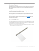
Tools Required The following tools are required to service the computer. Note that a special access card (part 922-7172) is required to open the front bezel.
Serial Number Location iMac serial numbers are located on the bottom of the computer stand. Note: iMac computers using Intel processors will not have the G5 listed in the configuration (as shown below).
Safety Warning: When the iMac is under power, be aware that the power supply contains high voltages that pose a potential hazard to your personal safety. Never work on or near the power supply with the unit powered on, and as a further precaution always make sure the unit is unplugged when working on it with the front bezel removed. WARNING: HIGH VOLTAGE Text or photographs marked by this symbol indicate that a potential hazard to your personal safety exists from a high voltage source.
Opening the Computer Apple authorized, desktop certified technicians only should ever remove the front bezel on the iMac. When the front bezel is removed, be sure to always ground yourself and follow ESD-safe repair practices Removing the front bezel requires using a special access card (part 922-7172) to release latches located inside the upper corners of the front bezel. Slightly bending the upper quarter of the access tool card will help engage the latch more securely.
2. Cut the EMI gasket to the edge of the access card. 3. Using packing tape, or something equivalent, fold the tape over the EMI gasket to attach the gasket to the card.
4. Bend the card at a slight angle at the top to make sure the card makes contact with each latch. 5. Refer to Removing the Front Bezel for the complete procedure.
EMI Shielding The iMac enclosure is wrapped in EMI shielding that is easily torn and damaged. To maintain a properly shielded unit, you must repair all accidental tears and cracks to the shielding by covering them with EMI tape. Order ������������������������������������������������������������ EMI tape, part number 922-4786 (a long, thin strip) or 9225026 (short, wide strips). Cover nicks, such as the those shown below, with EMI tape.
Lower EMI Shield EMI tape covers the top and sides of the display panel, and the lower EMI shield covers the logic board along the bottom of the unit. The EMI tape and lower EMI shield are easily damaged when removed, and removal is necessary in order to access most components within the unit. Should the EMI tape that seals the display, or the EMI shield covering the bottom of the enclosure (see photo below) accidentally tear, use EMI tape (922-4786 or 922-5026) to repair and completely seal the unit.
Pay particular attention to the EMI shielding inside the rear housing, shown below. The EMI shield is easily damaged when replacing modules Lower EMI Shield EMI tape covers the top and sides of the display panel, and the lower EMI shield covers the logic board along the bottom of the unit. The EMI tape and lower EMI shield are easily damaged when removed, and removal is necessary in order to access most components within the unit.
When properly repaired, all edges shown below will be wrapped by EMI tape, and the tape securely adhered to all edges. Use a black stick to flatten the EMI tape tightly and rub out air pockets and wrinkles.
What’s New 23 April 2007 • • The optical drive removal procedure has been updated. Using a screwdriver to release the optical drive tabs is causing damage to the logic board. The updated procedure shows how to remove the optical drive using a needlenose pliers. Additional information on handling slot-load optical drives can be referenced in Kbase article 305282. 12 January 2007 • The “No Power” symptom in Troubleshooting has been updated.
• • • • Logic board (661-4116) Hard Drive (661-4175) Stand (922-7832) Screw, T10, Flat head (922-7749) 11 July 2006 • Updated the screw chart with photos of 922-7654 and 922-7655 5 July 2006 • Introduction: iMac (17-inch Mid 2006) • Troubleshooting LEDs on the logic board • Logic board, dual core 1.
Service Source Take Apart iMac (17-inch Mid 2006), iMac (17-inch Late 2006 CD) © 2005 Apple Computer, Inc. All rights reserved.
Access Door Tools • • • Phillips #2 screwdriver. ESD-safe workstation and mat Soft, clean towel or cloth Preliminary Steps Before you begin, lay the computer down so the panel is face down and the bottom is facing you.
Removing the Access Door 1. Raise the stand and use a Phillips #2 screwdriver to loosen the two captive screws that secure the memory access door. Remove the access door. Replacing the Access Door 1. Make sure the memory ejector tabs are in the closed position before attaching the access door. 2. Position the access door on the rear housing over the memory compartment. 3. Lift the stand out of the way. 4. Use a Phillips #2 screwdriver to tighten the captive screws.
Memory Tools • • • Phillips #2 screwdriver. ESD-safe workstation and mat Soft, clean towel or cloth Preliminary Steps Before you begin, lay the computer down so the panel is face down and the bottom is facing you.
Removing the Memory Important: Always discharge static before you touch any parts such as the memory board. To avoid generating static electricity, do not walk around the room until you have finished replacing the memory. 1. Pull the two levers in the memory compartment toward you. Pull HARD! If a memory module is installed in the slot, pulling the levers will dislodge it. Note: The levers are used to remove memory not to install memory. . Always install memory with your fingers. 2.
Replacing the Memory 1. Make sure the DIMM levers are all the way open. 2. With the computer face down, orient the DIMM with the notch on the left. 3. With your fingers, press the DIMM fully into the slot until you hear a click. After inserting the memory, fold the DIMM levers closed. There will be a slight resistance and you will hear a click when they fold into the closed position. 4. Replace the access door on the memory compartment. 5.
Front Bezel Tools • • Access card tool 922-7172 Torx T8 screwdriver Preliminary Steps Before you begin, follow steps for removing the access door and the memory.
Removing the Front Bezel 1. With the bottom facing toward you use a T8 torx screwdriver to remove the four bezel mounting screws. Note: The screw to the right of the door is longer. 2. Stand the computer upright. 3. Located the access card tool. Bend the upper quarter of the access tool card slightly to engage the front bezel latches. Note: Refer to Access Tool Modification in the General Information chapter if the bezel is difficult to open. Note: Shown in the order they were removed.
4. This picture is intended to show how the access tool disengages the latch. Pushing the tool up the vent on the rear cover releases the latch on the inside of the front bezel. Refer to the next step for the procedure. 5. Start on the left side (looking from the back of the unit). Insert the card to disengage the latch. Squeeze the top of the bezel, that will help take pressure off of the latch and enable it to open easier. As the bezel releases, pull the bezel away from the rear housing.
6. Repeat step 5 to release the locking latch in the right corner. Again, pull the bezel away as the card releases the latch. 7. If the bezel won’t release, pull the bottom of the bezel out a bit and insert the access card again.
8. Repeat step 7 for the left side. 9. Once the access card has been removed, it is safe to open the bezel. Position the unit on an ESD mat, with the bottom facing toward you. Caution: Make sure the memory levers are closed and not protruding from the bezel when removing the bezel.
10. Lift the bottom of the front bezel straight up to remove it, and swing the bezel over onto its top edge so you can disconnect two cables attached to the top of the bezel.
11. Swing the bezel up so you can disconnect the two camera board cables Remove the any kapton tape and disconnect the camera and microphone cables from the camera board.. 12. If replacing a damaged front bezel, remove the camera board.
Replacing the Front Bezel 1. Position the front bezel near the top edge of the unit and connect the two camera board connectors. 2. Make sure the black EMI shielding along the top of the LCD panel is not in the way of the locking mechanisms when you lower the front bezel onto the computer. Use a black stick to press (re-stick) the EMI shielding along the top of the panel. 3. Tuck the cables neatly into the channel on the rear housing.
Note: Shown in the order they were removed. 922-7011, short 922-7749, long 4. Make sure the memory ejector levers are in the closed position (as shown) before lowering the front bezel over the ejectors. 5. Continue to lower the font bezel down and press the top corners of the front bezel to connect the latches. Note: Check that the latches are connected by lifting the front bezel at each corner. 6. Replace the four bezel screws along the bottom of the computer. 7.
Camera Board Tools The only tool required for this procedure is a T6 screwdriver. Preliminary Steps Before you begin, follow steps for removing the access door and front bezel.
Removing the Camera Board 1. The camera board and cables are visible as you lift the front bezel off the computer. 2. Disconnect the camera and microphone cables.
3. Using a T6 screwdriver, peel back the mylar and kapton tape as necessary and remove the two camera board mounting screws. Pull the camera board straight out of the lens aperture in the bezel to remove it.
Replacing the Camera Board 922-7713 1. Carefully align and insert the camera lens until it is snug in the bezel aperture. 2. Install the camera board to the bezel with two mounting screws. 3. Replace the front bezel. 4. Replace the access door.
Lower EMI Shield Tools The only tool required for this procedure is a “black stick” (or other nonconductive nylon or plastic flat-blade tool).
Removing the Lower EMI Shield 1. Carefully peel the lower EMI shield off the bottom edge and side of the rear housing. Use a black stick to help peel back the shield. 2. If replacing a torn or damaged lower EMI shield, peel the lower EMI shield off the bottom edge of the display. Replacing the Lower EMI Shield 1. Position the lower EMI shield over the bottom of the unit so that the holes in the shield are properly aligned. 2.
IR Board Tools • Torx T8 screwdriver (magnetized) Preliminary Steps Before you begin, follow steps for removing the following: • Access door • Front bezel • Lower EMI shield Part Location iMac (17-inch Mid 2006/Late 2006 CD) Take Apart — IR Board 39
Removing the IR Board 1. Using a Torx T8 screwdriver, remove the two IR screws and disconnect the IR cable from the IR board connector. Remove the IR board from its mounting bracket. 922-7655 Replacing the IR Board 1. Install the IR board and two mounting screws. 2. Connect the IR cable to the IR board connector. 3. Replace the lower EMI shield. 4. Replace the front bezel. 5. Replace the access door.
iMac (17-inch Mid 2006/Late 2006 CD) Take Apart — IR Board 41
AirPort Extreme Card Tools The only tool required for this procedure is a Torx T6 screwdriver (magnetized).
Removing the AirPort Extreme Card 1. Disconnect the antenna cable from the AirPort Extreme card connector and remove the two T6 screws securing the card to the logic board. 2. The card will spring up when the screws are removed. Grab the card from the connector end, pull the card from its socket on the logic board.
Replacing the AirPort Extreme Card 922-7010 1. Install the AirPort Extreme card into the socket. 2. Install the two mounting screws securing the card to the logic board. 3. Connect the AirPort antenna cable to the connector closest to the memory slot. 4. Replace the lower EMI shield. 5. Replace the front bezel. 6. Replace the access door.
Battery Tools The only tool required for this procedure is a black stick.
Removing the Battery 1. Pry the battery from the battery slot. Replacing the Battery 1. Slide the battery (with voltage information face up) into the battery holder. 2. Replace the lower EMI shield. 3. Replace the front bezel. 4. Replace the access door.
iMac (17-inch Mid 2006/Late 2006) Take Apart — Battery 47
LCD Display Tools • • • Torx T10 screwdriver Torx T6 screwdriver Black stick (or other nonconductive nylon or plastic flat-blade tool) Preliminary Steps Before you begin, follow steps for removing the following: • Access door • Front bezel • Lower EMI shield Part Location iMac (17-inch Mid 2006/Late 2006 CD) Take Apart — Display Panel 48
Removing the LCD Display 1. Using the black stick, or access tool, carefully peel back the EMI shielding from the left, right, and bottom edges of the computer 2. Using a Torx T6 screwdriver, remove the two LVDS cable connector screws. Disconnect the LVDS display cable from the logic board. Below the LVDS connector, disconnect the inverter cable from the logic board.
3. Peel the EMI tape away from each side of the panel. Using a Torx T10 screwdriver, remove the four panel mounting screws. 4. Pivot the panel up, as shown, then carefully peel the top edge of the panel away from the EMI shield.
Note: If replacing a bad LCD display, you will also need to remove the lower EMI shield (if still attached), the display panel mounting brackets, and the LVDS cable as follows. 5. If attached, peel the lower EMI shield off the bottom edge of the display panel. 6. Using a torx T10 screwdriver, push the tape aside and remove two screws from the left side panel mounting bracket. Repeat for the other side. 7.
8. To access the LVDS cable connector, peel back the black mylar tape that partially covers the LVDS connector. 9. Remove the tape securing the LVDS connector to the panel connector.
10. Pinch together the connector locking levers, and disconnect the LVDS cable connector. 11. Return the panel to Apple.
Replacing the LCD Display 1. Replace the LVDS cable on the rear of the display panel. 2. Secure the LVDS cable with tape. 3. If you are replacing the display, a piece of black mylar is enclosed in the box with the display module. The dotted lines below show the correct placement of the mylar. Note: The LVDS locking lever (on one side) should be covered by the mylar when positioned correctly.
922-7158 922-7023 4. Replace the right panel mounting bracket on the display panel with two screws. 5. Replace the left bracket on the display panel with two screws. 6. Connect the two inverter-to-display cable connectors and tape them to the back of the display panel. Tape the middle inverter cable to the back of the display as well. 7. Turn over the panel. If the lower EMI shield was removed, reattach the lower EMI shield across the bottom of the panel. 8.
LVDS Display Cable Tools No tools are required to remove the LVDS (Low Voltage Differential Signaling) cable.
Remove the LVDS Cable 1. Locate the LVDS cable on the back side of the display panel. Remove the piece of tape (circled) that secure the cable to the panel. To access the connector, peel back the black mylar tape that partially covers the LVDS connector. 2. Remove the tape securing the LVDS connector to the panel connector.
3. Pinch together the connector locking levers, and disconnect the LVDS cable connector.
Replacing the LVDS Cable 1. Position the LVDS cable on the back of the display panel as shown. 2. Connect the LVDS cable connector. When connected correctly the locking levers will secure the connector and it cannot be disconnected without depressing the levers. 3. Secure the LVDS cable to the panel with one strip of tape.
4. Replace the display panel. Note: If you are replacing the display, a piece of black mylar is enclosed in the box with the display module. The dotted lines below show the correct placement of the mylar. The LVDS locking lever (on one side) will be covered by the mylar when positioned correctly. 922-7023 ( 5. Replace the lower EMI shield. 6. Replace the front bezel. 7. Replace the access door.
Inverter Tools Removing the inverter requires using a flat-blade screwdriver Preliminary Steps Before you begin, follow steps for removing the following: • Access door • Front bezel • Lower EMI shield • LCD Display Part Location iMac (17-inch Mid 2006/Late 2006 CD) Take Apart — Inverter 61
Removing the Inverter 1. Remove three pieces of tape that secure the inverter cables to the back of the display panel, and disconnect the two white inverter connectors shown. 2. Using a flat-blade screwdriver as shown, pry up the inverter to remove it from inside the display panel mounting bracket.
Replacing the Inverter 1. Insert the long, black inverter cable through a hole at the back center of the right mounting bracket, and press the sticky side of the replacement inverter onto the back edge of the bracket. 2. Connect the inverter-to-display cables and tape them to the back of the display panel. . 3. Replace the display panel. 4. Replace the lower EMI shield. 5. Replace the front bezel. 6. Replace the access door.
Speakers Tools • • Torx T10 screwdriver (magnetized) Torx T6 screwdriver (magnetized) Preliminary Steps Before you begin, follow steps for removing the following: • Access door • Front bezel • Lower EMI shield • LCD Display Part Location iMac (17-inch Mid 2006/Late 2006 CD) Take Apart — Speaker 64
Removing the Speakers 1. Using a T10 torx screwdriver, remove the screws from the left and right speakers. Replacement Note: The longer of the two speaker mounting screws is used to secure the left speaker; the shorter screw secures the right speaker. 2. Lift the speakers straight up and disconnect the speaker cable under the right speaker.
Replacing the Speakers 1. Connect the speaker cable connector to the logic board. 2. Install the speakers and route the speaker wire above the heatsink and around the fan. 3. Secure the right speaker with the shorter of the two mounting screws. 4. Secure the left speaker with the longer of the two mounting screws. 5. Replace the display panel. 6. Replace the EMI shield. 7. Replace the front bezel. 8. Replace the access door.
Optical Drive Tools • • • Torx T10 screwdriver (magnetized) Torx T6 screwdriver (magnetized) Needlenose pliers (with teeth) Preliminary Step Before you begin, follow steps for removing the following: • Access door • Front bezel • Lower EMI shield • LCD Display Part Location iMac (17-inch Mid 2006/Late 2006 CD) Take Apart — Optical Drive 67
Removing the Optical Drive 1. Disconnect the sensor cable from the temperature sensor on top of the optical drive and remove the two T10 screws from the optical drive clip on the logic board. 2. Note: Make sure to use a needlenose pliers with teeth to remove the optical drive. The pliers must have a textured surface to properly grasp the optical drive release tabs.
3. Locate the black tabs at each side of the plastic optical drive mounting bracket. Starting at the release tab that is furthest from the logic board, grasp the tab with needlenose pliers, and flex the tab toward the optical drive flexible cable. (Note: This graphic shows a different iMac model, but the removal procedure is the same for each model.) Use one finger underneath the edge of the optical drive to gently lift up that corner of the drive.
4. Warning: iMac main logic boards returned with physical damage such as scratches, fractures, or broken or missing components caused by improper servicing may be classified as customer abuse. When using a tool to release the latches, be careful not to apply pressure to the logic board or it may be damaged. While avoiding the logic board, grasp the tab with needlenose pliers, and flex the tab toward the optical drive.
5. Lift the rear of the drive and pull the front bezel of the drive straight back and out of the disc opening in the rear housing. 6. If replacing a bad optical drive, use a T6 torx screwdriver to remove two optical drive board mounting screws. Disconnect and keep the board for installation on the replacement drive. 7. If replacing a bad optical drive, also remove the temperature sensor from the top of the drive. Discard the sensor—the replacement drive comes with a new sensor already installed.
Replacing the Optical Drive 1. If removed, install the optical drive board to the optical drive with two T6 screws. 2. Insert the optical drive “bezel-end-first” into the opening in the housing. Be sure to align the two guide holes in the front bezel with guide posts at each end of the bezel opening. 922-7656 Push down on the black mounting bracket to lock the optical drive securely into place on the chassis.
iMac (17-inch Mid 2006/Late 2006 CD) Take Apart — Optical Drive 73
Hard Drive Tools: • • • Torx T10 screwdriver (magnetized) T8 Flat-blade screwdriver Preliminary Steps Before you remove: • Access door • Front bezel • Lower EMI shield • LCD display Part Location iMac (17-inch Mid 2006/Late 2006 CD ) Take Apart — Hard Drive 74
Remove the Hard Drive 1. Position yourself at the base of the computer closest to the stand. 2. Pull in on the edge of the mounting bracket until you feel it release from the chassis. Pull HARD! The hard drive bracket will release on the end near your hands. 3. Disconnect the hard drive power and data cables. Set the hard drive aside.
4. Note: If you are replacing a bad hard drive, remove the mounting bracket and the mounting pins shown in the following steps before returning the bad drive to Apple. 5. Using a T10 torx screwdriver, remove two screws and the mounting bracket from the drive. 6. Using a T8 torx screwdriver, remove two mounting pins from the other side of the drive.
Replacing the Hard Drive 922-7019 922-7001 1. If necessary, install two mounting pins on side of the hard drive mounting bracket. 2. If necessary, install the mounting bracket to the top of the hard drive with two screws. 3. Connect the hard drive power and data cables. 4. Insert the hard drive mounting pins and position the drive on the chassis. Make sure the hard drive power and data cables are routed correctly and don’t get pinched as you lower the drive into the chassis.
iMac (17-inch Mid 2006/Late 2006 CD ) Take Apart — Hard Drive 78
Power Supply The iMac (17-inch MId 2006/Late 2006 CD) computer was built with two versions of the power supply: • Version 1: iMac (Mid 2006) power supply • Version 2: iMac (Early 2006) power supply This procedure provides instructions for replacing both versions. Note: The power supplies must be replaced like for like.
Part Location Version 1 Power Supply (661-4018) ( Version 2 Power Supply (661-3780) iMac (17-inch Mid 2006/Late 2006 CD) Take Apart — Power Supply 80
About the Power Supply Warning: When the iMac is under power, be aware that the power supply contains high voltages that pose a potential hazard to your personal safety. Never work on or near the power supply with the unit powered on, and as a further precaution always make sure the unit is unplugged when working on it with the front bezel removed. WARNING: HIGH VOLTAGE Text or photographs marked by this symbol indicate that a potential hazard to your personal safety exists from a high voltage source.
Removing the Power Supply Version 1 Power Supply (661-4018) 1. WARNING: HIGH VOLTAGE Disconnect the AC power inlet connector on the left and the power supply-to-logic board connector on the right. Note: The power supply connector is on the underside of the logic board. See the next photo for another view of the connector underneath the logic board. 2. Rotate the computer so that the stand is away from you. Locate the power supply connector underneath the logic board.
3. Using a T8 screwdriver, remove the two self-tapping screws on the left side of the power supply board and the two machine screws on the right side of the board. Note: Self-tapping screw labeled S1 is longer than self-tapping screw S2. 4. Remove the power supply from the enclosure.
Version 2 Power Supply (661-3780) 1. WARNING: HIGH VOLTAGE Disconnect the short AC power inlet connector on the right side of the power supply board, and the power supply-to-logic board connector at the top of the board. 2. Using a T10 screwdriver, Remove the T10 AC power inlet ground-to-chassis screw.
3. Using a T10 screwdriver, remove the three self-tapping screws on the top and left sides of the power supply board and the one machine screw on the lower right corner of the board. 4. Remove the power supply from the enclosure. 5. If you are replacing the power supply-to-logic board cable, disconnect the cable from the logic board and remove the cable from the enclosure. Note: To disconnect the cable, do the following: • Rotate the computer so that the stand is away from you.
Replacing the Power Supply Power Supply (661-4018) 1. WARNING: HIGH VOLTAGE Position the power supply loosely in its mounting location. 2. Connect the power supply-to-AC power inlet cable. Tuck the cable beneath the chassis and away from the hard drive bay. 3. Connect the power supply-to-logic board cable to the underside of the logic board. 4. Install the four power supply screws, starting with the machine screw in the lower right corner of the power supply.
Logic Board Tools Removing the optical drive requires using the following tools: • Torx T10 screwdriver (magnetized) Preliminary Steps Before you begin, follow steps for removing the following: • Access door • Front bezel • Lower EMI shield • LCD display • Hard Drive • Optical drive • Speakers • Memory Part Location iMac (17-inch Mid 2006/Late 2006 CD) Take Apart — Logic Board 87
Removing the Logic Board 1. Disconnect the ten cables from the connectors on the logic board. Note: The speakers would already be removed. 2. Using a T10 torx screwdriver, remove the screws from the logic board. Note the locations of the three self-tapping screws (marked by and “S” in the photo). The rest of the screws are machine screws.
3. Rotate the unit so the power supply is in the bottom right corner and the optical drive is on your left. With a black stick, disconnect the power supply cable on the underside of the logic board. 4. Pull the board toward you and slightly lift the board up. Note: The I/O ports fit tightly into the port hole openings on the rear cover. You may have to fidget with the board a bit to free the ports from the rear cover. Remove the logic board out of the rear housing.
Replacing the Logic Board 1. Pull all cables up and away from the logic board bay and gently place down the logic board so that all screw holes are aligned with screw mounts in the chassis. Replacement Note: The logic board should rest on the screw mounts without any binding or bowing—if it doesn’t, adjust any cables that are interfering with the logic board. 2. Install the optical drive. 3.
5. Replace the hard drive. 6. Replace the speakers. 7. Replace the display panel. 8. Replace the lower EMI shield. 9. Replace the front bezel. 10. Replace the memory. 11. Replace the memory access door.
CPU Fan Tools No tools are required to remove the CPU fan.
Removing the CPU Fan 1. Lift the CPU fan off the white mounting posts. Replacing the CPU Fan 1. Align the CPU fan with the two mounting posts in the rear housing, and push it straight down onto the posts. Note: Route the antenna cable under the fan (as shown above), but pull it aside (to the left side) when installing the logic board. 2. Replace the logic board. 3. Replace the optical drive. 4. Replace the hard drive. 5. Connect the CPU fan cable and the rest of the cables to the logic board. 6.
Optical Drive Fan Tools No tools are required to remove the optical drive fan.
Remove the Optical Drive Fan 1. Lift the optical drive fan straight up and off three mounting posts. Replace the Optical Drive Fan 1. Align and install the optical drive fan on three mounting posts. Push it down snug onto the posts. 2. Replace the logic board. 3. Replace the optical drive. 4. Replace the hard drive. 5. Replace the speakers. 6. Replace the display panel. 7. Replace the lower EMI shield. 8. Replace the front bezel. 9. Replace the memory. 10. Replace the memory access door.
Hard Drive Fan Tools No tools are required to remove the optical drive fan.
Remove the Hard Drive Fan 1. Carefully pull the hard drive fan cable from under the chassis. 2. Lift the hard drive fan straight up and off three mounting posts. Replacing the Hard Drive Fan 1. Route the hard drive fan cable under the metal chassis and above the I/O ports. 2. Align and install the hard drive fan on mounting posts. Push it down snug onto the posts. 3. Replace the logic board. 4. Replace the optical drive. 5. Replace the hard drive. 6. Replace the speakers. 7.
AC Power Inlet Tools Removing the AC power inlet requires using the following tools: • Torx T10 screwdriver (magnetized) Preliminary Steps Before you begin, follow steps for removing the following: • Access door • Front bezel • Lower EMI shield • LCD display • Hard Drive • Optical drive • Speakers • Memory • Logic board • Hard drive fan Part Location iMac (17-inch Mid 2006/Late 2006) Take Apart — AC Power Inlet 98
Removing the AC Line Filter 1. Using a torx T10 screwdriver, remove the three self-tapping screws from the power inlet. 2. Using a torx T10 screwdriver, remove the machine screw from the power inlet ground cable. 3. Peel the EMI tape off the power inlet. 4. Disconnect the power inlet-to-power supply cables and unlace the power inlet cable from beneath the chassis.
Replacing the AC Line Filter 1. Install the AC power inlet on the rear housing screw mounts with three self tapping screws. 2. Install the power inlet ground cable to the chassis with a machine screw. 3. Route the power inlet cable beneath the chassis as shown in the photo above, and connect it to the power supply. 4. Using EMI tape, securely tape the top and bottom edges of the AC power inlet to the rear housing. 5. Replace the hard drive fan. 6. Replace the logic board. 7.
iMac (17-inch Mid 2006/Late 2006) Take Apart — AC Power Inlet 101
Ambient Light Sensor Board Tools No tools are required to remove the ambient light sensor board.
Removing the Ambient Light Sensor Board 1. Remove the rubber bumper from between the chassis and the board. 2. With a black stick, pry the ambient light sensor board from the frame.
Replacing the Ambient Light Sensor Board 1. Press the sticky side of the ambient light sensor board to the bottom inside edge of the rear housing. 2. Install the rubber bumper between the back of the ambient light sensor board and the chassis. 3. Replace the logic board. 4. Replace the optical drive. 5. Replace the hard drive. 6. Replace the speakers. 7. Replace the display panel. 8. Replace the lower EMI shield. 9. Replace the front bezel. 10. Replace the memory. 11.
iMac (17-inch Mid 2006/Late 2006) Take Apart — ALS Board 105
Clutch Mechanism Tools Removing the clutch requires using the following tools: • Torx T10 screwdriver (magnetized) Preliminary Steps Before you begin, follow steps for removing the following: • Access door • Front bezel • Lower EMI shield • LCD display • Hard Drive • Optical drive • Speakers • Memory • Logic board • Hard drive fan Part Location iMac (17-inch Mid 2006/Late 2006 CD) Take Apart — Clutch 106
Removing the Clutch 1. Carefully peel the three pieces of EMI tape up and off the metal clutch cover. 2. Remove the metal clutch cover.
3. Using a T10 torx screwdriver, remove the four clutch mounting screws. 4. Stand up the unit and remove the four T10 clutch-to-stand mounting screws. Separate the clutch from the rear housing and the stand.
Replace the Clutch 1. Make sure the stand is erect and the end of the stand is inserted through the mounting hole in the rear housing. 2. Position the clutch on the stand with the spring at bottom right. Install the four long, clutchto-stand mounting screws. 3. Adjust the clutch so that its chassis mounting holes align, and install the four machine screws that secure the clutch to the chassis. 4. Replace the optical drive. 5. Replace the hard drive fan. 6. Replace the logic board. 7.
AirPort Antenna Tools Removing the wireless antenna requires using the following tools: • Flat-blade screwdriver • Black stick (or other nonconductive nylon or plastic flat-blade tool) Preliminary Steps Before you begin, follow steps for removing the following: • Access door • Front bezel • Lower EMI shield • LCD display • Hard Drive • Optical drive • Speakers • Memory • Logic board • CPU fan Part Location iMac (17-inch Mid 2006/Late 2006 CD) Take Apart — AirPort Antenna 110
Removing the AirPort Extreme Antenna 1. Carefully peel back the tape (circled) and the EMI backing from the top left inside corner of the rear housing as shown below. Peel back just enough EMI backing to access the antenna board. Using a flat-blade screwdriver, pry the antenna board off the rear housing. 2. Remove any tape that secures the antenna cable to the rear housing. 3. Pull the antenna cable through the access hole in the EMI shield at the top, near the antenna board.
Replacing the AirPort Extreme Antenna 1. Locate the antenna mounting channel inside the left corner of the rear housing, and position the antenna board in the channel. Compress the sticky side of the antenna board to the housing until securely fastened. 2. Route the antenna cable through the EMI shield and on top of the EMI. 3. Secure the antenna cable to the housing with two pieces of tape. 4. Replace the CPU fan. 5. Replace the logic board. 6. Replace the DC power supply. 7.
Camera Cable Tools No tools are required to remove the camera cable.
Removing the Camera Cable 1. Disconnect the two camera board cables from the logic board. 2. Disconnect the camera cables and pull the cable through the access hole at the top of the EMI shield. Remove the camera cable from the rear housing.
Replacing the Camera Cable 1. Insert the camera cables through the access hole in the upper EMI shield. Replace any Kapton tape or EMI grounding tape. The EMI tape should secure the cable to the metal chassis. 2. Route the camera cable around the hard drive and under the chassis (as shown). Connect the two cables to the connectors on the logic board.
3. Replace the hard drive (if removed). 4. Replace the optical drive. 5. Replace the display panel. 6. Replace the lower EMI shield. 7. Replace the front bezel. 8. Replace the memory access door.
Chassis Tools Removing the chassis requires using the following tools: • Torx T10 screwdriver (magnetized) Preliminary Steps Before you begin, follow steps for removing the following: • Access door • Front bezel • Lower EMI shield • LCD display • Hard Drive • Optical drive • Speakers • Memory • Logic board • CPU fan • Hard drive fan • Optical fan • AC Power Inlet • Clutch mechanism iMac (17-inch Mid 2006/Late 2006 CD) Take Apart — Chassis 117
Part Location Removing the Chassis 1. With all the other parts removed, use a T10 torx screwdriver to remove the self-tapping screws circled below. Lift the chassis from the rear housing.
Replacing the Chassis 1. Position the chassis on the rear housing and install the self-tapping mounting screws. 2. Replace the clutch mechanism. 3. Replace the AC power inlet. 4. Replace the three fan fans. 5. Replace the power supply. 6. Replace the hard drive. 7. Replace the optical drive. 8. Replace the logic board. 9. Replace the speakers. 10. Replace the display panel. 11. Replace the lower EMI shield. 12. Replace the front bezel. 13. Replace the memory access door.
Rear Housing Tools No tools are required to remove the rear housing in addition to those referenced below.) Remove and Replace the Rear Housing To remove the rear housing, follow steps for removing the parts below. Reverse these steps to replace the rear housing.
Service Source Troubleshooting iMac (17-inch Mid 2006) and iMac (17-inch Late 2006 CD) © 2006 Apple Computer, Inc. All rights reserved.
General Information Serial Number iMac serial number is located on the bottom of the computer stand. Power On Self Test (POST) Intel-based Mac computers rely on a combination of tones and blinking LEDs to display Power On Self Test (POST) error codes. • If the computer detects out-of-specification or no SDRAM or the RAM installed does not meet the appropriate specifications, the screen will remain black but the power LED on the front of the computer will blink once per second to signal the error.
DDR Memory The iMac computer has two SDRAM slots in the bottom of the computer. The iMac ships from the factory with at least 512 MB of DDR2 SDRAM, installed as a 256 MB DIMM in the top slot and a 256 MB DIMM in the bottom slot. (The computer may come with more RAM, depending on how the computer was ordered from Apple.) Although you can install a single SO-DIMM, it is recommended that memory be installed in matched pairs for improved graphics performance.
How to Reset the System Management Controller (SMC) The System Management Controller (SMC) is a chip on the logic board that controls all power functions for your computer. If your computer is experiencing any power issue, resetting the SMC may resolve it. The SMC controls several functions, including: • Telling the computer when to turn on, turn off, sleep, wake, idle, and so forth. • Handling system resets from various commands. • Controlling the fans. Note that resetting the SMC does not reset the PRAM.
Diagnostic LEDs The iMac has three built-in diagnostic LEDs and a front LED on the main logic board (shown below) that can help you to troubleshoot the computer. To Access the LEDs: 1. Follow the take apart instructions to remove the RAM access door, front bezel, and lower EMI shield. 2. Locate the SO-DIMM slot and LVDS video connector. The three troubleshooting LEDs 1, 2, and 3 are located to the right of the LVDS cable connector, under a square of black tape. Peel back the tape to view the LEDs.
LED #1 Indicates that the trickle voltage from the power supply has been detected by the main • logic board. This LED will remain ON whenever the iMac (Mid 2006 17-inch) is connected to a working AC power source. The LED will remain on even when the computer has been shut down or put to sleep. The LED will turn off only if the AC power source is disconnected or the power supply is faulty.
Symptom Charts How to Use the Symptom Charts The Symptom Charts included in this chapter will help you diagnose specific symptoms related to the product. Because cures are listed on the charts in the order of most likely solution, try the cures in the order presented. Verify whether or not the product continues to exhibit the symptom. If the symptom persists, try the next cure. Note: If a cure instructs you to replace a module, reinstall the original module before you proceed to the next cure.
Power Issues No Power The iMac will not turn on. The display remains black and there are no sounds from the fans or drives. 1. Verify the power outlet is good. Plug a different device into the socket to ensure there is power, or plug the iMac into another outlet. Does the iMac power on now? Yes: Resolved. Bad outlet. No: Go on to the next step. 2. Check the power cord. Use a known good power cord. Does the iMac power on now? Yes: Your power cord has failed. Replace the AC power cord.
8. Press the power button. Check to see if LED # 2 comes On, comes on momentarily, or stays Off. LED # 2 is On: The Power Supply is functioning. Go on to the next step. LED # 2 comes on momentarily or stays Off: Replace the Power Supply. 9. At this point in the Power On process, you should hear a boot chime and see the front LED on the computer light up. When the main logic board and LCD panel communicate to deliver video, the front LED should go off, and LED # 3 should be on.
No Video No Video, No Boot Chime, White LED ON (Symptom 1) The iMac will turn on (indicated by the front LED ON), but there is NO boot chime and No Video on the display. The faint sound of the fans, hard drive, and optical drive may also be heard. 1. Follow instructions in the “General Information” chapter to reset the SMC. Does the computer display video after successfully resetting the SMC? Yes: Problem solved. No: Continue to next step. 2.
3. Does the computer display video after successfully resetting the computer’s PRAM? Yes: Restart the computer from the Apple menu and make sure the computer is now working correctly. No: Continue to next step. 4. Make sure the machine is powered off; power off the machine by holding in the Power Button on the rear of the machine. Turn on the machine. Observe the white LED on the front bezel during startup; it should go out after a few moments.
Starts Up to Black Screen or No Video (iMac 17-inch Mid 2006 only) Refer to Knowledge Base article 303870 or follow the procedure below. An iMac (17-inch Mid 2006) may start up to a black screen (with no video). It may also occur if you have just changed the brightness of the display. If this happens, the computer will sound like it’s starting up, but the display stays black.
Display When displaying a single color over the screen area, the LCD panel shows one or more pixels that are not properly lit Active-matrix LCD technology uses rows and columns of addressable locations (pixels) that render text and images on screen. Each pixel location has three separate subpixels (red, green, and blue) that allow the image to be rendered in full color. Each subpixel has a corresponding transistor responsible for turning the subpixel on or off.
Hard Drive Flashing question mark, or an alternating question mark and Mac OS (face or a folder) Note: When troubleshooting hard drive problems it is a good idea, if possible, to back up any important data. Some troubleshooting steps may require erasing the contents of the hard drive. 1. Boot from the system CD that came with the computer, and open Disk Utility. Does the hard drive show in Disk Utility? Yes: Run Repair Disk and Repair Permissions to correct any directory and permissions issues.
System hangs during normal startup process 1. Boot from the system CD that came with the computer. Use Disk Utility to verify the hard drive. 2. Using Disk Utility, reformat the hard drive. 3. Check all cable connections to and from the hard drive. 4. Replace the hard drive data cable. 5. Replace the hard drive. 6. Replace the logic board.
Optical Drive CDs or DVDs don’t show up on the Desktop. 1. Select Preferences from the Finder menu and make sure the option to show CDs, DVDs and iPods is checked: in the General window as shown below.
2. Select System Preferences from the Apple menu and open the CDs & DVDs preferences window. Make sure that audio CDs are set to launch iTunes and movie DVDs set to launch DVD Player when those media are inserted, as shown below. 3. Check that the drive can read discs normally. Insert an audio CD and check whether it shows up on your desktop or launches iTunes. Does the audio CD mount on the desktop or in iTunes? Yes: The drive seems to read CD discs okay. Go on to Step 4.
The computer won’t burn discs. 1. Check whether the drive can read CDs and DVDs normally. Perform the steps above for “CDs or DVDs don’t show up on the Desktop.” 2. Try a test burn by creating a Burn Folder, as follows. • In the Finder, choose “New Burn Folder” from the File menu. • Open the Burn Folder, drag an item inside for testing, and click “Burn” in the upper right corner of the window. • When prompted, insert a blank disc and follow the dialog instructions.
No: Replace the optical drive. Does it burn correctly now? Yes: Problem solved. No: Replace the logic board. Discs won’t insert. 1. Is there a disc already in the drive? Yes: Eject the disc before inserting another. Refer to Knowledge Base article 51008 - “iMac: If You Can’t Eject a CD or DVD, or Open the Drive Tray”. If none of these options will eject the disc, you may have to disassemble the drive to recover the disc.
Optical disc constantly ejects 1. Disconnect all peripheral devices, especially the mouse in cases where the disc is constantly ejecting. Retest. If the issue is resolved, reconnect peripherals one-at-a-time until faulty peripheral is identified. 2. Try cleaning the disc. If the disc is dirty or scratched, it may not mount. Is the issue resolved? Yes: Problem solved. No: Try a different disc. If the issue persists, go on to the next step. 3.
Fan Sound Fans running at full speed after the computer turns on The customer may have entered a diagnostic mode that causes the fans to run at full speed.* Restarting the system will not restore normal fan operation. To solve the problem, the user or technician should do the following: 1. Shut down the system. 2. Disconnect the power cord and wait 15 seconds. 3. Reconnect the power cord and wait 5 seconds. 4. Power on the system.
sound is related to one of the components. Go to step 4. The sound varies: Under normal conditions rotating blowers will make a slight hum that varies in relationship with their rotational speed and the amount of air that they are moving. Let’s see if this is indeed the case. Go to Next Step. 3. Are the fans making a normal humming sound that increases/decreases in relation to processor usage? As the fans increase their speed to cool the system the sound level will increase.
remove the access door, front bezel, and EMI shield. Stand up the computer, plug it in, and start it up by pressing the external power button. As the machine starts up, listen carefully to each of the three fans, and see if you can locate the fan from which the objectionable ticking, whistling, or squealing sound is coming. The CPU fan is the left-most fan, the hard drive fan is in the center, and the optical drive fan is on the right. Can you pinpoint the fan making the sound? Yes: Replace the noisy fan.
AirPort Not able to connect wirelessly with AirPort 1. From the Apple menu, choose About this Mac. 2- Click on More Info. System Profiler should open. 3- In System Profiler, in the column on the left, look under Network for a line called “AirPort Card”. Select that line. 4- Does the section to the right say “No Information Found”? Yes: The computer doesn’t realize it has an AirPort card installed. Go to step. 5 No: The iMac recognizes that it has an AirPort card installed. Go to step 6.
IR Remote Remote won’t communicate with system applications such as iTunes or iPhoto, or with the optical drive. Make sure of the following when using the Apple Remote: • You are within 30 feet of the front of the computer. • You have an unobstructed line-of-sight to the front of the computer. • You are pointing the lens end of the Apple Remote directly at the front of the computer. • The computer is powered on and awake.
IR Sensor/Receiver Supported applications do not respond to input from the remote control. 1. Perform the checks above under “IR Remote” to verify that the Apple Remote is functioning correctly, and retest. Do supported applications now respond to input from the IR remote? Yes: Problem resolved. No: Go to the next step. 2. Verify that the IR Sensor can be seen in the Apple System Profiler. Open the Apple System Profiler and click on the “USB” section.
Built-in iSight Camera The built-in camera is not recognized. 1. Boot the iMac to the desktop and launch iChat AV. Note: You do not need to be connected to a network to use iChat AV to troubleshoot. Verify that the correct versions of Mac OS X and iChat AV are installed. Reinstall or update software as needed. 2. Open the iChat AV preferences and click on the ‘Video’ icon. Verify whether the camera is recognized by the iChat AV software.
bandwidth limitations when using iChat over the internet. Instruct the customer to use the iChat AV connection doctor feature to verify that there is sufficient bandwidth to have a video iChat session without a significant degradation of image quality. No: The camera may not be functioning normally. Replace the camera board in the front bezel and retest. Camera recognized but no audio 1. Open the System Preferences window and click on Sound. 2.
Speakers Can’t hear sound from the speakers. 1. Disconnect any external microphones, speakers, or headphones. 2. Access System Preferences and select Sound. In the Sound pane, select Output and make sure the Internal speakers are selected as the device for sound output, the Output volume is adequate, and Mute is not selected. Do you have sound now? Yes: Problem resolved. No: Go to the next step. 3. Reset parameter RAM. Press Command-Option-P-R during startup but before “Welcome to Macintosh” appears.
6. If the speakers did not solve the problem, replace the logic board. Mouse My mouse doesn’t work at all. 1. Turn over the mouse and check the if the red LED on the underside of the mouse. Is the LED lit? Yes: The mouse has power. Try using the mouse on another surface. Non-reflective, opaque surfaces without repetitive patterns work best. The surface should be clean, but not shiny. Optical mice won’t work on glass, mirrored surfaces, glossy materials or mouse pads with pictures.
Keyboard Certain keys or none of the keys on the keyboard function. 1. Unplug all devices from your computer, including your mouse and keyboard as well as printer, scanner, external hard drives, and hubs. (Warning: Some devices may require you to perform steps before it is safe to unplug them, e.g., external storage devices.) Be sure to unplug your hub, if you have one. 2. Plug your keyboard into the back of your computer firmly and securely.
6. Close the System Preferences. Try typing a few characters. Did is solve the problem? Yes: Problem solved. No: Replace the keyboard. The USB port on my keyboard doesn’t work. 1. Unplug all devises from your keyboard. 2. Plug your Apple mouse into the left USB port on your keyboard. Does your mouse work when it’s plugged into this port? Yes: Now plug the mouse into the right port. Does it work? Yes: Try a known good keyboard. No: Try a known good mouse to rule out the mouse. Then go to step 3.
USB A USB device doesn’t work 1. Please unplug all of your USB devices from your iMac except your Apple Keyboard and Apple mouse. 2. Now plug your device directly into the back of your iMac. Does it work as expected now? Yes: Your device works when plugged directly into the computer. This indicates a conflict with one of the other USB devices. You can test by gradually adding your devices back and seeing where the issue occurs, then contacting the manufacturer of the device(s)) for assistance.
iMac (17-inch (Mid 2006/Late 2006 CD) Troubleshooting — Symptom Charts 154
Service Source Views iMac (17-inch Mid 2006) and iMac (17-inch Late 2006 CD) © 2006 Apple Computer, Inc. All rights reserved.
Upper Exploded View iMac (17-inch Mid 2006) and iMac (17-inch Late 2006 CD) Lower EMI Shield 922-7653 Camera Board 661-3811 Front Bezel 922-7243 Access Door 922-7246 LCD Display, 17 Inch 661-4020 LVDS Cable 922-7642 Left Bracket 922-7078 Optical Temp.
Lower Exploded View Optical Drive Fan 922-7062 CPU Fan 922-7641 HD Mounting Bracket 922-7057 HD Power Cable 922-7646 HD SATA Cable 922-7645 Hard Drive Fan 922-7643 Hard Drive 661-3943 80 GB, 7200 661-4175 160 GB, 7200 Hard Drive Pins 922-7001 Camera Cable / Microphone 922-7675 Clutch 922-7074 Wireless Antenna 922-7649 IR Board 922-7639 Chassis 922-7247 IR Cable 922-7648 Not shown: EMI tape 922-5026 EMI tape 922-4786 Rear Cover 922-7657 AC Power Inlet 922-7155 Stand 922-7651 (Mid 2006) 922-7832 (Lat
Screw Chart Screw Chart Page 1 iMac (17-inch Mid 2006/Late 2006 CD) 922-6800 T10 Logic board to rear cover (3) 922-6842 Note: Screws are not to scale.
Screw Chart Page 2 922-7020 T10 922-7023 T10 922-7066 T10 Clutch mechanism to chassis((4) LCD assembly to rear cover via left and right brackets (4) Power supply to rear chassis (2) 922-7067 922-7068 922-7069 T10 T10 T10 Left speaker to rear cover (1) Right speaker to rear cover(1) AC power inlet ground to chassis (1) 922-7158 922-7159 922-7654 T8 T8 T10 Left and right LCD bracket to LCD (4) Power supply to (top right corner) rear chassis (1) Power supply to (bottom left corner) re
iMac (17-inch Mid 2006/Late 2006 CD) Views 160