Service Source iMac (17-inch Flat Panel, 1GHz) © 2003 Apple Computer, Inc. All rights reserved.
iMac (17-inch Flat Panel, 1GHz) -1
Service Source Take Apart iMac (17-inch Flat Panel, 1GHz) © 2003 Apple Computer, Inc. All rights reserved.
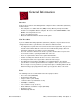
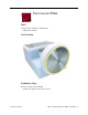
General Information Overview Some of the key features that distinguish this computer from the earlier iMac (Flat Panel) models include: • This computer uses double-data rate (DDR) memory. Memory from previous iMac models is not compatible with this computer. Do not use older SDRAM DIMMs or SODIMMs even if they fit into the slot. • There is an audio line in jack. • Bluetooth and AirPort Extreme Card are CTO options.
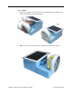
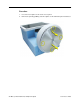
Service Stand 1. Support the computer by neck and the base (A). Gently position the computer in the service stand with the flat panel facing up (B). 2. Note: The base of the computer can be rotated when servicing internal parts.
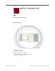
User Access Plate Tools This procedure requires the following tools: • Phillips #0 screwdriver Part Location Preliminary Steps Before you begin, do the following: • Position the computer in the service stand.
Procedure 1. Loosen the four captive screws on the access panel. 2. Remove the panel by grabbing onto two captive screws and lift the panel off the base.
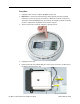
AirPort Extreme Card Tools This procedure requires no tools. Part Location Preliminary Steps Before you begin, do the following: • Position the computer in the service stand. • Remove the user access plate.
Procedure 1. Unplug all cables from the computer except the power cord. 2. Important: To avoid electrostatic discharge, always ground yourself by touching metal before you touch any parts or install any components inside the computer. To avoid static electricity building back up in your body, do not walk around the room until you have completed the installation and closed the computer. 3. Touch a metal surface inside the computer to ground yourself. 4. Unplug the power cord. 5.
Memory, SO-DIMM (userinstallable) Tools No tools are required for this procedure. Part Location Preliminary Steps Before you begin, do the following: • Position the computer in the service stand. • Remove the user access plate. Note: DIMMs used in this slot should be a low-profile PC2100 (DDR266) SO-DIMM. Only the SO-DIMM slot is accessible by the user.
Procedure 1. Unplug all cables from the computer except the power cord. 2. Important: To avoid electrostatic discharge, always ground yourself by touching metal before you touch any parts or install any components inside the computer. To avoid static electricity building back up in your body, do not walk around the room until you have completed the installation and closed the computer. 3. Touch a metal surface inside the computer to ground yourself. 4. Unplug the power cord. 5.
6. Allow the memory to pop up slightly, and pull it out of the memory slot.
Bottom Housing Tools This procedure requires the following tools: • Torx-15 screwdriver Part Location Preliminary Steps Before you begin, do the following: • Position the computer in the service stand. • Remove the user access plate.
Procedure 1. When opening the bottom housing, rotate the base so the optical drive door is on the right. (This position is less stressful on the internal cables when the bottom is open). 2. Remove the four torx screws. Replacement Note: These torx screws must be tightened to at least 17 in.-lbs. If you do not have a torque driver, you will have to make sure these screws are tightened by hand FIRMLY, BUT NOT FORCIBLY.
3. Gently open the bottom housing in the direction of the arrow. Disconnect the cables.
4. Disconnect the following: A Grounding screw B Bluetooth connector (if present) C AirPort connector D AC line filter connector E TMDS video connector F Inverter, speaker, fan connector G Optical cable and connector H Hard drive cable and connector I Power Supply connector 5. Set the bottom housing aside. Warning: Whenever the bottom housing is opened for service, you must do two things: 1.
Thermal Paste Application Tools This procedure requires the following tools: • Plastic stylus or plastic spatula to remove the old thermal paste • Plastic stylus or plastic spatula to spread the thermal paste • Thermal paste (922-4757) Part Location 14 - iMac (17-inch Flat Panel, 1GHz) Take Apart Thermal Paste Application
Procedure 1. Thoroughly clean the original thermal film from the mating surfaces (circled below) of the bottom housing and thermal pipe. Use a plastic stylus to scrape the surfaces clean. Note: Do not use an abrasive material or liquid cleaner. 2. Squeeze a ball of thermal paste onto the mating surfaces of the thermal pipe.
3. Replace the bottom housing. Warning: The bottom housing has four torx screws that must be tightened to at least 17 in.-lbs. Use a torque driver (service tool 076-0899) to ensure that the thermal pipe is firmly mated with the top base. If you do not have a torque driver, you must make sure the screws are tightened by hand FIRMLY, BUT NOT FORCIBLY.
RJ-11 Modem Filter Board Tools This procedure requires the following tools: • Torx-6 screwdriver Part Location Preliminary Steps Before you begin, do the following: • Position the computer in the service stand. • Remove the user access plate. • Remove the bottom housing.
Procedure 1. Remove two screws and disconnect the cable from the modem. 2. Remove the RJ-11 board from the I/O port. Warning: Whenever the bottom housing is opened for service, you must do two things: 1.You must clean the original thermal film from all thermal interface mating surfaces, and reapply thermal paste to the mating surfaces on the thermal pipe. 2. You must tighten the four torx screws on the bottom housing to a minimum of 17 in.-lbs.
Modem Tools This procedure requires the following tools: • Torx-8 screwdriver Part Location Preliminary Steps Before you begin, do the following: • Position the computer in the service stand. • Remove the user access plate. • Remove the bottom housing.
Procedure 1. Remove two screws and disconnect the cable. 2. Lift the modem board from the connector on the logic board. Warning: Whenever the bottom housing is opened for service, you must do two things: 1.You must clean the original thermal film from all thermal interface mating surfaces, and reapply thermal paste to the mating surfaces on the thermal pipe. 2. You must tighten the four torx screws on the bottom housing to a minimum of 17 in.-lbs.
Memory (factory-installed) Tools This procedure requires the following tools: • No tools are required Part Location Preliminary Steps Before you begin, do the following: • Position the computer in the service stand. • Remove the user access plate. • Remove the bottom housing.
Procedure 1. Push down on the ejector tabs to release the memory module. 2. Pull the memory up and out of the slot. Important: Make sure that the memory installed on the logic board is compatible with the system. The computer accepts double-data rate (DDR) SDRAM DIMMs. DIMMs used in this slot must fit the following specification: PC2100 SDRAM DDR266 DIMMs for 133 MHz systems. Warning: Whenever the bottom housing is opened for service, you must do two things: 1.
Battery Tools This procedure requires the following tools: • No tools are required Part Location Preliminary Steps Before you begin, do the following: • Position the computer in the service stand. • Remove the user access plate. • Remove the bottom housing.
Procedure 1. Using a flatblade screwdriver, gently pry the battery from the battery holder. Warning: Whenever the bottom housing is opened for service, you must do two things: 1.You must clean the original thermal film from all thermal interface mating surfaces, and reapply thermal paste to the mating surfaces on the thermal pipe. 2. You must tighten the four torx screws on the bottom housing to a minimum of 17 in.-lbs.
Logic Board Tools This procedure requires the following tools: • Phillips #2 screwdriver (for the plastic screw) • Torx-15 screwdriver Part Location Note: The battery, RJ-11 board, AirPort card, modem, I/O port covers, and memory (on the top and the bottom of the logic board) need to be removed from the logic board before returning the board to Apple for service. Preliminary Steps Before you begin, do the following: • Position the computer in the service stand. • Remove the user access plate.
Procedure 1. Remove the three torx screws (metal) and one plastic screw.
2. Grab the logic board by the battery retainer and the hard drive connector. Lift the board slightly and pull back to release the board from the bottom housing and I/O ports. Note: The I/O port covers may come out with the logic board when it’s removed. 3. Remove the I/O port covers from the logic board. Warning: Whenever the logic board is separated from the bottom housing, you must install new thermal pads to three surfaces on the bottom housing.
Bluetooth Board, Wireless Tools This procedure requires the following tools: • Phillips #2 jeweler’s screwdriver Part Location Preliminary Steps Before you begin, do the following: • Position the computer in the service stand. • Remove the user access plate. • Remove the bottom housing. • Remove the RJ-11 board. • Remove the logic board.
Procedure 1. Ground yourself. Remove the AirPort card and SO-DiMM memory (if present). 2.
3. Remove the two screws (circled below) on the Bluetooth board. Peel back the Kapton tape to release the Bluetooth antenna. Note: You don’t have to disconnect the Bluetooth antenna (shown by the arrow) from the board. 4. Next, lift the Bluetooth board from the connector on the logic board. Warning: Whenever the logic board is separated from the bottom housing, you must install new thermal pads to three surfaces on the bottom housing.
I/O Port Covers Tools This procedure requires the following tools: • No tools are required Part Location Preliminary Steps Before you begin, do the following: • Position the computer in the service stand. • Remove the user access plate. • Remove the bottom housing. • Remove the RJ-11 board • Remove the logic board.
Procedure 1. Gently pull the I/O port covers off the logic board. Warning: Whenever the bottom housing is opened for service, you must do two things: 1.You must clean the original thermal film from all thermal interface mating surfaces, and reapply thermal paste to the mating surfaces on the thermal pipe. 2. You must tighten the four torx screws on the bottom housing to a minimum of 17 in.-lbs. Use a torque driver (service tool 076-0899) to ensure that the thermal pipe is firmly mated with the top base.
AirPort Antenna Extension Cable Tools This procedure requires the following tools: • No tools are required Part Location Preliminary Steps Before you begin, do the following: • Position the computer in the service stand. • Remove the user access plate. • Remove the bottom housing. • Remove the RJ-11 board • Remove the logic board.
Procedure 1. Release the extension cable from the plastic cable clips to remove the cable from the bottom housing. Replacement Note: Be careful not to pinch the antenna extension cable when replacing it. Warning: Whenever the bottom housing is opened for service, you must do two things: 1.You must clean the original thermal film from all thermal interface mating surfaces, and reapply thermal paste to the mating surfaces on the thermal pipe. 2.
Thermal Pad Installation Tools • No tools are required. • Thermal pad kit (076-0925) Part Location Warning: Whenever the logic board is separated from the bottom housing, you must install new thermal pads to two surfaces on the bottom housing. Failure to apply these pads whenever the logic board is separated from the bottom housing could cause these parts to overheat and could damage internal components.
Procedure 1. Remove the old thermal pads from the bottom housing. Note: If you don’t see the two thermal pads on the bottom housing, check the under side of the logic board. The thermal pads may stick to the logic board. Always remove the old thermal pads, and install new pads if you are taking the unit apart to this level. 2. Using the thermal pad kit, remove the clear protective backing from the new thermal pads. 3. Place the new thermal pads on the bottom housing.
AC Line Filter Tools This procedure requires the following tools: • Torx-10 screwdriver Part Location Preliminary Steps Before you begin, do the following: • Position the computer in the service stand. • Remove the user access plate. • Remove the bottom housing. • Remove the RJ-11 board. • Remove the logic board.
Procedure 1. Peel the black insulator on the bottom housing back to access the AC line filter screws. 2. Remove two screws and lift the AC line filter from the bottom housing. Note: The port plug may fall out of the AC filter port when you remove the AC line filter. Replace the plug into the opening on the bottom housing before reinstalling the AC line filter.
Warning: Whenever the bottom housing is opened for service, you must do two things: 1.You must clean the original thermal film from all thermal interface mating surfaces, and reapply thermal paste to the mating surfaces on the thermal pipe. 2. You must tighten the four torx screws on the bottom housing to a minimum of 17 in.-lbs. Use a torque driver (service tool 076-0899) to ensure that the thermal pipe is firmly mated with the top base.
Drive Carrier Assembly (Optical and Hard Drive) Tools This procedure requires the following tools: • Torx-10 screwdriver Part Location Preliminary Steps Before you begin, do the following: • Position the computer in the service stand with the door facing up. • Remove the user access plate. • Remove the bottom housing.
Procedure 1. Rotate the base unit so the optical drive door is facing to the right. 2. Remove six screws; two on the EMI shield (with copper tape) and four attaching the drive to the Faraday cage (chassis). Carefully lift the shield and copper tape off the drive. Replacement Note: When replacing the drive EMI shield, be sure to use the two shorter screws.
3. Remove the Airport and Bluetooth antennas from the plastic clip on the side of the drive carrier.
4. Grasp the carrier by the top and bottom edges. Wiggle the drive carrier out of the chassis pulling the carrier in the direction of the arrow. Note: The carrier fits snugly into the chassis. 5. Disconnect the two power cables; one attaches to the optical drive and the other attaches to the hard drive.
6. To remove the hard drive from the carrier, peel the white wrapper up to access the screws (two on each side). Remove the screws, disconnect the data cable, and remove the hard drive out of the carrier. 7. To remove the optical drive, remove four screws (shown by dashed lines), disconnect the optical drive data cable (see lower arrow), and slide the optical drive out of the carrier.
Warning: Whenever the bottom housing is opened for service, you must do two things: 1.You must clean the original thermal film from all thermal interface mating surfaces, and reapply thermal paste to the mating surfaces on the thermal pipe. 2. You must tighten the four torx screws on the bottom housing to a minimum of 17 in.-lbs. Use a torque driver (service tool 076-0899) to ensure that the thermal pipe is firmly mated with the top base.
Power Supply Tools This procedure requires the following tools: • Torx-10 screwdriver Part Location Preliminary Steps Before you begin, do the following: • Position the computer in the service stand and rotate the door to the right. • Remove the user access plate. • Remove the bottom housing. • Remove the drive carrier assembly.
Procedure 1. Remove the two power supply screws circled below.
2. Open the optical drive door as shown. Support the metal plate and power supply as you remove the four screws. Important: The two screws near the door hinge are shorter than the other power supply screws. Failure to replace the shorter screws into their correct location will scratch the top housing. See step 4, Replacement Note.
3. Lift the power supply and metal shield out of the chassis (Faraday cage). 4. Replacement Note: When replacing the metal shield (see picture above) that sits on top of the power supply, install the two shorter screws near the optical door. If the longer screws are installed by mistake, the screws will scratch the inside of the housing (circled below).
Warning: Whenever the bottom housing is opened for service, you must do two things: 1.You must clean the original thermal film from all thermal interface mating surfaces, and reapply thermal paste to the mating surfaces on the thermal pipe. 2. You must tighten the four torx screws on the bottom housing to a minimum of 17 in.-lbs. Use a torque driver (service tool 076-0899) to ensure that the thermal pipe is firmly mated with the top base.
Optical Drive Door Tools This procedure requires the following tools: • Torx-10 screwdriver • Needlenose pliers Part Location Preliminary Steps Before you begin, do the following: • Position the computer in the service stand. • Remove the user access plate. • Remove the bottom housing. • Remove the drive carrier assembly.
Procedure 1. Remove four screws on the power supply shield. Set the shield aside. Important: The two screws near the door hinge are shorter than the other power supply screws. Failure to replace the shorter screws to their correct location will scratch the top housing. See the Power Supply topic, step 4, Replacement Note, for a picture of what happens when the wrong screws are inserted in the wrong location.
2. Slide the optical door guide off the chassis and the door hinge tabs (circled). 3. Carefully remove the two door springs with a needlenose pliers.
4. Remove the door hinge screws. 5. Open the door.
6. Slide the door and hinge off the chassis. Warning: Whenever the bottom housing is opened for service, you must do two things: 1.You must clean the original thermal film from all thermal interface mating surfaces, and reapply thermal paste to the mating surfaces on the thermal pipe. 2. You must tighten the four torx screws on the bottom housing to a minimum of 17 in.-lbs. Use a torque driver (service tool 076-0899) to ensure that the thermal pipe is firmly mated with the top base.
Speaker, Internal Tools This procedure requires the following tools: • Torx-10 screwdriver Part Location Preliminary Steps Before you begin, do the following: • Position the computer in the service stand. • Remove the user access plate. • Remove the bottom housing. • Remove the drive carrier assembly.
Procedure 1. Loosen the two screws enough to slide the speaker off the metal posts. Disconnect the speaker cable. Warning: Whenever the bottom housing is opened for service, you must do two things: 1.You must clean the original thermal film from all thermal interface mating surfaces, and reapply thermal paste to the mating surfaces on the thermal pipe. 2. You must tighten the four torx screws on the bottom housing to a minimum of 17 in.-lbs.
Fan Tools This procedure requires the following tools: • Torx-15 screwdriver Part Location Preliminary Steps Before you begin, do the following: • Position the computer in the service stand. • Remove the user access plate. • Remove the bottom housing. • Remove the drive carrier assembly.
Procedure 1. Remove the two fan screws and disconnect the fan connector. 2. Pull the fan out of the chassis (Faraday cage). Note: The replacement fan includes the mounting bracket. Warning: Whenever the bottom housing is opened for service, you must do two things: 1.You must clean the original thermal film from all thermal interface mating surfaces, and reapply thermal paste to the mating surfaces on the thermal pipe. 2. You must tighten the four torx screws on the bottom housing to a minimum of 17 in.
Power Supply Insulators Tools No tools are required for this procedure. Part Location Note: Insulator color and transparency may vary from those shown above. Preliminary Steps Before you begin, do the following: • Position the computer in the service stand. • Remove the user access plate. • Remove the bottom housing. • Remove the drive carrier assembly. • Remove the power supply.
Procedure 1. Carefully pull the insulators from the chassis (Faraday cage). These are attached to the chassis with double-sided tape. Warning: Whenever the bottom housing is opened for service, you must do two things: 1.You must clean the original thermal film from all thermal interface mating surfaces, and reapply thermal paste to the mating surfaces on the thermal pipe. 2. You must tighten the four torx screws on the bottom housing to a minimum of 17 in.-lbs.
Fan Retainer Bracket (under fan) Tools This procedure requires the following tools: • Torx-10 screwdriver Part Location Preliminary Steps Before you begin, do the following: • Position the computer in the service stand. • Remove the user access plate. • Remove the bottom housing. • Remove the drive carrier assembly. • Remove the power supply. • Remove the fan.
Procedure 1. Remove the four screws connecting the fan bracket to the chassis (Faraday cage). 2. Lift the fan bracket out of the chassis. Note the orientation of the neck cables (see below) in the fan bracket before removing the cables. For orientation purposes, the drive door would be on the right.
Warning: Whenever the bottom housing is opened for service, you must do two things: 1.You must clean the original thermal film from all thermal interface mating surfaces, and reapply thermal paste to the mating surfaces on the thermal pipe. 2. You must tighten the four torx screws on the bottom housing to a minimum of 17 in.-lbs. Use a torque driver (service tool 076-0899) to ensure that the thermal pipe is firmly mated with the top base.
Fan Gasket Tools No tools are required for this procedure. Part Location Preliminary Steps Before you begin, do the following: • Position the computer in the service stand. • Remove the user access plate. • Remove the bottom housing. • Remove the drive carrier assembly. • Remove the power supply. • Remove the fan. • Remove the fan retainer bracket.
Procedure 1. Remove the fan retainer bracket and turn it over. Gently peel the fan gasket off the back of the fan bracket. Warning: Whenever the bottom housing is opened for service, you must do two things: 1.You must clean the original thermal film from all thermal interface mating surfaces, and reapply thermal paste to the mating surfaces on the thermal pipe. 2. You must tighten the four torx screws on the bottom housing to a minimum of 17 in.-lbs.
Cap, Neck Spoke Retainer Tools This procedure requires the following tools: • Torx-10 screwdriver Part Location Preliminary Steps Before you begin, do the following: • Position the computer in the service stand. • Remove the user access plate. • Remove the bottom housing. • Remove the drive carrier assembly. • Remove the power supply. • Remove the fan.
Procedure 1. Before removing the neck cap screws, note the cable routing, including the location of the empty spoke. 2. Note: There are five screws on the neck cap. For this step, remove only the three silver screws and the neck cap. (The two black screws secure the neck to the base.
Warning: Whenever the bottom housing is opened for service, you must do two things: 1.You must clean the original thermal film from all thermal interface mating surfaces, and reapply thermal paste to the mating surfaces on the thermal pipe. 2. You must tighten the four torx screws on the bottom housing to a minimum of 17 in.-lbs. Use a torque driver (service tool 076-0899) to ensure that the thermal pipe is firmly mated with the top base.
Chassis (Faraday Cage) Tools This procedure requires the following tools: • Torx-10 screwdriver • Torx-8 screwdriver for the logo screw Part Location Preliminary Steps Before you begin, do the following: • Position the computer in the service stand. • Remove the user access plate. • Remove the bottom housing. • Remove the drive carrier assembly.
• • • • Remove the power supply. Remove the fan. Remove the plastic cable retainer (under the fan). Remove the neck spoke retainer cap. Procedure 1. Pull the neck cables/white spokes out of their slots and into a bundle. Bundle the neck cables to one side. Supporting the base, remove the two black screws that connect the neck to the Faraday base.
2. Carefully feed the neck cables through the hole in the Faraday cage. Important: The Faraday cage is very heavy and has sharp edges; handle with care.
3. Pull the outer shell (with Faraday attached) away from the neck.Note: There is no need to remove the outer shell from the Faraday unless you are replacing the antenna or the outer shell. If you are removing the shell from the Faraday cage, go on to the next step. 4. Note: Perform this step only if you are replacing the antenna or the outer shell. Remove one screw in the base of the Faraday cage to separate the shell from the Faraday cage.
Replacement Notes: Faraday cage: Look at the exploded view diagram during reassembly. First, attach the Faraday top cover to the top (OUTSIDE) of the Faraday cage as shown below; the Faraday top cover is keyed. Next, thread the neck cables through the hole in the Faraday cage and install the Faraday cage into the top plastic housing. Replace the screw that holds the plastic housing to the chassis. Attach the black neck cap screws to connect the neck to the chassis.
AirPort Antenna Tools This procedure requires the following tools: • Torx-8 screwdriver Part Location Preliminary Steps Before you begin, do the following: • Position the computer in the service stand. • Remove the user access plate. • Remove the bottom housing. • Remove the drive carrier assembly. • Remove the power supply. • Remove the power supply insulators. • Remove the optical drive door. • Remove the internal speaker. • Remove the fan.
• • • • Remove the fan bracket under the fan. Remove the neck spoke retainer cap. Remove the blind mate connector screws. Remove the Faraday cage.
Procedure 1. Remove the mounting screw and unclip the board from the Faraday cage. Remove any tape, and carefully separate the antenna board cable from the Faraday cage. 2. Remove the second mounting screw to unclip the antenna from the Faraday cage.
Warning: Whenever the bottom housing is opened for service, you must do two things: 1.You must clean the original thermal film from all thermal interface mating surfaces, and reapply thermal paste to the mating surfaces on the thermal pipe. 2. You must tighten the four torx screws on the bottom housing to a minimum of 17 in.-lbs. Use a torque driver (service tool 076-0899) to ensure that the thermal pipe is firmly mated with the top base.
2. Feed the antenna wires through the hole in theFaraday cage and position the wires against the Faraday cage (as shown). Make sure that the wires lay flat against the inside of the Faraday cage.. 3. Place the copper tape over the wires making sure the wires lay flat. Press the copper tape securely against the Faraday cage. 4. Reassemble the computer and return the system to the customer.
Housing, Outer Shell, Plastic Tools This procedure requires the following tools: • Torx-10 screwdriver Part Location Preliminary Steps Before you begin, do the following: • Position the computer in the service stand. • Remove the user access plate. • Remove the bottom housing. • Remove the drive carrier assembly. • Remove the power supply. • Remove the power supply insulators. • Remove the optical drive door. • Remove the fan. • Remove the fan bracket under the fan.
• Remove the neck spoke retainer cap. • Remove the blind mate connector screws.
Procedure 1. Remove the two black screws that connect the neck to the base. 2. Carefully feed the neck cables through the hole on the vent cap shown below.
3. Next, carefully separate the outer plastic housing from the neck. 4. Remove one screw in the base of the Faraday cage to separate the white outer shell from the Faraday cage.
Warning: Whenever the bottom housing is opened for service, you must do two things: 1.You must clean the original thermal film from all thermal interface mating surfaces, and reapply thermal paste to the mating surfaces on the thermal pipe. 2. You must tighten the four torx screws on the bottom housing to a minimum of 17 in.-lbs. Use a torque driver (service tool 076-0899) to ensure that the thermal pipe is firmly mated with the top base.
Display, Flat Panel Tools This procedure requires the following tools: • 1.5 mm hex tool • Torx-10 screwdriver Important: If you are replacing the display, be sure to install the new display shield and EMI gaskets that come with the new LCD panel. Installation instructions are included with the new display panel Part Location Preliminary Steps Before you begin, do the following: • Position the computer in the service stand.
Procedure 1. Remove three screws that connect the back cover to the flat panel LCD display.
2. Support the back cover and pull back the display (as shown) to separate it from the base.
3. Caution: The power on LED cable (labelled A below) is fragile. When disconnecting display cables, be sure to raise the TOP SIDE of the display only. Carefully raise the TOP SIDE of the display and disconnect the inverter cable (B) and remove the TMDS cables (C) from the metal cable clip. Note: Enlarge the page to view the graphic at a larger size. 4. Raise the display to access the TMDS connector. Peel back the black tape.
5. Disconnect the TMDS connector by squeezing the clip (1) on each side of the connector. Gently pull the cable (2) out of the slot. 6. Caution: The power on LED cable (labelled A below) is fragile. Raise the top of the display to access the power on LED (A below) and microphone (B below) cables. Peel back the tape and disconnect the cables.
7. Remove four screws that connect the LCD display panel to the display bezel. Peel back the tape on the EMI shield to remove the LED (A) and microphone (B) cables from the display. 8. Remove the display from the bezel. Replacement Note: If you are replacing the display, be sure to install the new display shield and EMI gaskets that come with the new LCD panel. Installation instructions are included with the new display panel. 9.
Replacing the Display 1. After connecting the display cables, position the display into the rear housing. Place the display into the rear housing, sliding it into position, pushing it in the direction of the arrows. Note: The display mates with tabs/slots in the rear housing. If the display doesn’t fit properly and you can’t install the three screws along the bottom of the housing, check that the display is properly seated in the rear housing. 2.
3. Check the alignment of the rear housing and the flat panel display. If the display doesn’t slide into the tabs/slots on the rear housing, a white line shows across the back of the rear housing (see below). 4. A properly installed display will have no white line showing across the back of the rear housing (see below), and the three display-to-housing screw holes align perfectly.
Inverter Tools This procedure requires no tools. Part Location Preliminary Steps Before you begin, do the following: • Position the computer in the service stand. • Remove the flat panel display.
Procedure 1. Remove the tape (circled below) and disconnect the cables. Peel back the edge of the EMI shield to access the foil on the inverter. 2. Peel the foil off the inverter (A). Pull the inverter off the edge of the display panel (B).
LED Note: Do not remove the LED from the bezel. The LED is part of the display bezel (9225297); it cannot be ordered separately. Important: The LED does not light up when the power is on; however, the LED should pulse when the computer is in Sleep mode. Part Location Preliminary Steps Before you begin, do the following: • Remove the flat panel display.
Microphone Note: Do not remove the microphone from the bezel. The microphone is part of the display bezel (922-5297); it cannot be ordered separately. Part Location Preliminary Steps Before you begin, do the following: • Remove the flat panel display.
Back Cover, Display Tools This procedure requires the following tools: • Torx-10 screwdriver Part Location Preliminary Steps Before you begin, do the following: • Position the computer in the service stand. • Remove the flat panel display.
Procedure 1. Note the position of the inverter (A), TMDS (B), microphone (C), and LED (D) cables. Remove four screws that secure the metal wire deflector and the base assembly to the back cover. Remove the wire deflector. 2. Remove tape from the neck cables and pull them through the hole in the back cover. Note: The hole in the back cover is notched; align the wide TMDS connector with these notices to pull it through the back cover.
Neck Assembly Tools This procedure requires the following tools: • Torx-10 screwdriver Part Location Preliminary Steps Before you begin, do the following: • Position the computer in the service stand. • Remove the user access plate. • Remove the bottom housing. • Remove the drive carrier assembly. • Remove the power supply. • Remove the power supply insulators. • Remove the fan.
• • • • • • • Remove the fan bracket. Remove the neck spoke retainer cap. Remove the blind mate connector screws. Remove the Faraday cage. Remove the outer plastic housing. Remove the flat panel display. Remove the back cover Procedure The neck assembly is attached to the computer base at one end and to the flat panel display at the other end. To remove the neck assembly from the computer, follow all the take-apart procedures.
Neck Assembly iMac (17-inch Flat Panel, 1GHz) Take Apart - 101
Service Source Troubleshooting iMac (17-inch Flat Panel, 1GHz) © 2003 Apple Computer, Inc. All rights reserved.
General Information Overview: Some of the key features that distinguish this computer from the earlier iMac (Flat Panel) models include: 1. The diagnostic test points have moved on the bottom of the logic board. They are now located near the AirPort Extreme Card slot. Refer to the topic, “Diagnostic Test Points” in this chapter for more information. 2. This computer uses double-data rate (DDR) memory; PC2100 DDR 266. Memory from previous iMac models is not compatible with this computer.
have new thermal paste applied each time the bottom housing is removed. If the mating surfaces are not cleaned and thermal paste is not used, the CPU may overheat and become damaged. There is no exception to this. Note: Most service procedures require that the bottom housing is removed. Refer to “Thermal Paste Application” mentioned later in this chapter or in the Take Apart chapter. 3.
Logic Board, Top General Information iMac (17-inch Flat Panel, 1GHz) Troubleshooting - 3
Logic Board, Bottom 4 - iMac (17-inch Flat Panel, 1GHz) Troubleshooting General Information
I/O Ports The PMU Chip The PMU (Power Management Unit) is a microcontroller chip that controls all power functions for the computer. The PMU (location shown below) is a computer within a computer. It has memory, software, firmware, I/O, two crystals, and a CPU. Its function is to: • Tell the computer to turn on, turn off, sleep, wake, idle, etc. • Manage system resets from various commands. • Maintain parameter RAM (PRAM). • Manage the real-time clock.
Resetting the PMU on the Logic Board Resetting the PMU (Power Management Unit) on the logic board can resolve many system problems. Whenever you have a unit that fails to power up, you should follow this procedure before replacing any modules. 1. Disconnect the power cord. 2. Remove the user access panel from the bottom of the computer. 3. Press the PMU reset switch (located under the protective cover, next to the test points) once on the bottom side of the logic board and then proceed to step 3.
Diagnostic Test Points The iMac has four test points and one ground pad on the bottom of the logic board (next to the PMU and AirPort Extreme Card). These test points are accessible under the customer access panel via small cutouts in the plastic shielding (see below). These test points provide an easy troubleshooting tool for common problems. To use each test point, put the positive probe of your voltmeter on the test point, and the negative probe on the ground pad.
Logic Board Battery Important: Apple highly recommends removing the battery when handling the logic board. Make sure to use proper ESD protection when handling modules. The battery on the logic board controls the stored system settings, such as date and time. It is only necessary to test the battery when you can’t power on the computer, or the date and time are reset every time the AC power is removed.
4. Connect the power cord and power up the system again. Warning: Whenever the bottom housing is opened for service, you must do two things: 1. You must clean and reapply thermal paste to the thermal pipe surface. 2. You must tighten the four torx bolts on the base unit to a minimum of 17 in.– lbs. Failure to follow either of these steps could cause the computer to overheat nd damage internal components. Refer to the next topic, “Thermal Paste Application” for detailed information.
Thermal Paste Application The following instructions explain how to apply thermal paste to the thermal pipe in the iMac (17-inch Flat Panel, 1GHz) computer. Failure to follow these instructions could cause the computer to overheat and damage internal components.
Procedure 1. Thoroughly clean the original thermal film from the four mating surfaces circled below. Use a plastic stylus to scrape the surfaces clean. Note: Do not use an abrasive material or liquid cleaner. 2. Squeeze a drop of thermal paste onto the thermal pipe locations circled below. 3. Close the bottom housing. Warning: The bottom housing has four torx screws that must be tightened to at least 17 in.-lbs.
Thermal Pad Replacement Instructions Whenever the logic board is separated from the bottom housing, you must install new thermal pads to three surfaces on the bottom housing. The thermal pads help cool components on the logic board. Failure to apply these pads whenever the logic board is separated from the bottom housing could cause these parts to overheat.
Symptom Charts How to Use the Symptom Charts The Symptom Charts included in this chapter will help you diagnose specific symptoms related to the product. Because cures are listed on the charts in the order of most likely solution, try the cures in the order presented. Verify whether or not the product continues to exhibit the symptom. If the symptom persists, try the next cure. Note: If you have replaced a module, reinstall the original module before you proceed to the next cure.
No Power No fan, no hard drive noise, and the screen is black. 1. Verify the power outlet is good. Plug a different device into the socket to ensure there is power, or plug computer into another outlet. 2. Check the power cord. Use a known good power cord. 3. Check connection of the power cord on both ends. Verify that the plug is securely plugged into both the A/C outlet and back of the computer. 4. Remove keyboard, mouse, and other peripherals such as speakers. 5.
11. Remove the bottom housing. Check that all the cables on the logic board are securely connected. Pay special attention to the video connector. Power on the unit again. If you still have no power, go on to the next step. Warning: Whenever the bottom housing is opened for service, you must do two things: • You must clean the original thermal film from the surfaces joining the thermal interface layer and reapply thermal paste to the thermal pipe.
No Video Screen is dark, fan is running and the hard drive is spinning. You may hear the startup chime as well. 1. Reset parameter RAM. Press Command-Option-P-R during startup before “Welcome to Macintosh” appears. 2. The system software could be damaged. Start up from the system CD that came with the computer. 3. Remove the user access panel on the bottom of the computer. With the unit powered on, check if a red LED is visible in the access door. If the red LED is on, power is on.
No LED LED on the display bezel does not light up Note: The LED does not light up when the power is on; however, the LED should pulse when the computer is in Sleep mode. 1. Put the computer into Sleep mode. Allow the machine to remain in sleep mode for one minute and then wake the computer to ensure the computer is waking from sleep mode. Does the LED pulse now? If yes, there is nothing wrong with the LED. If no, replace the display bezel (922-5297) shown below.
Display LED on the display bezel does not light up Note: The LED does not light up when the power is on; however, the LED should pulse when the computer is in Sleep mode. 1. Put the computer into Sleep mode. Does the LED pulse now? If yes, there is nothing wrong with the LED. If no, replace the display bezel (922-5297). The LED is attached to the display bezel and cannot be ordered separately. Display Tilt Screen tilts to the left or the right even after a manual adjustment.
3. Loosen the screws under the metal cable retainer and tilt the screen the opposite direction of the tilt. 4. While holding the display bezel in the level position, tighten the screws. 5. Replace the panel and check that the display is now horizontally level. Important: If you are replacing the display, be sure to install the new display shield and any EMI gaskets that may come with the new LCD panel.
When displaying a single color over the screen area, the LCD panel shows one or more pixels that are not properly lit Active-matrix LCD technology uses rows and columns of addressable locations (pixels) that render text and images on screen. Each pixel location has three separate subpixels (red, green, and blue) that allow the image to be rendered in full color. Each subpixel has a corresponding transistor responsible for turning the subpixel on or off.
Hard Drive Hard Drive won’t mount to the desktop 1. Disconnect any connected peripherals. 2. Boot from the system CD that came with the computer and see if the hard drive mounts on the desktop. 3. Launch Drive Setup and update the hard drive driver. 4. If no hard drive is found in Drive Setup, verify the hard drive cable connections. 5. Replace the hard drive cable. 6. Replace the hard drive. 7. Replace the logic board. Flashing question mark appears on the screen 1.
Optical Drive Optical drive won’t mount to the desktop 1. Try cleaning the disc. If it is dirty or scratched, it may not mount. 2. Try a different disc. 3. Boot from Apple Hardware Test (hold down the “C” key at startup) or boot from the system install CD (use Startup Manager, hold down the Option key at startup). 4. Perform a clean install with the CD that came with the computer. 5. Replace the optical drive cable. 6. Replace the optical drive. 7. Replace the logic board.
Sound Out No sound from either internal or external speakers 1. Verify volume setting is correct in system preferences. 2. Replace the external speakers or headphone in question with a known-good device. 3. Reset parameter RAM. Press Command-Option-P-R during startup before “Welcome to Macintosh” appears. 4. Verify internal speaker cable is connected. 5. Replace the internal speaker. 6. Replace the logic board.
Sound In No sound is recorded 1. Check setup of the system preferences for the microphone. 2. Check the microphone cable connection. 3. Replace the internal microphone. 4. Replace the neck assembly.
Error Beep(s) Computer beeps at startup. 1. RAM expansion DIMMs for the iMac must be PC133 compliant and use SDRAM devices. If the user installs a DIMM that uses EDO or SGRAM devices, the computer will beep several times when the user attempts to restart the computer. 2. Refer to “Power-On Self Test” mentioned earlier in this chapter.
Modem No modem dial tone 1. Verify known-good analog (not digital) telephone line. 2. Verify known-good RJ-11 telephone cable. 3. Verify RJ-11 cable is not plugged into Ethernet port. 4. Inspect RJ-11 connector and modem port for pin damage. 5. Verify RJ-11 cable is firmly installed in the modem port. 6. Verify correct modem driver is installed and the correct CCL is selected. If the problem persists, reinstall system software. 7. Open the bottom housing.
I/O Ports Difficulty Plugging in an Ethernet Cable Note: The Ethernet port on an iMac (Flat Panel, 1GHz) has a special mechanism to prevent modem cables from accidentally being inserted. In some cases, this mechanism can cause difficulty when attempting to plug in an Ethernet cable. 1. Verify that you are plugging into the Ethernet port. See graphic below. 2. Notice that the port has two metal tabs (circled below) which prohibit the use of a modem cable. 3.
Service Source Upgrades iMac (17-inch Flat Panel, 1 GHz) © 2003 Apple Computer, Inc. All rights reserved.
Memory, SO-DIMM Tools • #0 Phillips screwdriver. Part Location This computer uses double-data rate (DDR) memory. Memory from previous iMac models is not compatible with this computer. Do not use older SDRAM DIMMs or SO-DIMMs even if they fit into the slot. Note: This procedure describes installing a SO-DIMM memory module in the useraccessible slot.
Procedure Opening the Computer Warning: The computer must be turned off before RAM modules are removed or inserted. To remind you, a red LED is visible in the access door. If the red LED is on, power is on, and must be turned off before changing RAM modules. 1. Shut down the computer. 2. Unplug all cables from the computer except the power cord. 3. Lay the computer down on a soft cloth.
4. Loosen the four captive screws at the base of the computer and gently remove the access panel.
Important: To avoid electrostatic discharge, always ground yourself by touching metal before you touch any parts or install any components inside the computer. To avoid static electricity building back up in your body, do not walk around the room until you have completed the installation and closed the computer. 5. Touch a metal surface inside the computer. 6. Unplug the power cord.
Installing the Memory Module Note: If you are replacing a defective memory module, rather than adding a module, remove the defective module before proceeding. 1. Line up the notch on the memory module with the notch on the memory slot. Important: Do not push the slot clips (on each side) when inserting memory. They are used to remove memory from the slot, not to insert memory. These clips are fragile and could break. 2. Gently insert the memory module into the slot.
Closing the Computer 1. Replace the access panel and the four screws. 2. Reconnect all cables and restart the computer. Warning: Never turn on the computer unless all of its internal and external parts are in place and it is closed. Operating the computer when it is open or missing parts can damage your computer or cause injury.
AirPort Extreme Card Tools • #0 Phillips screwdriver to remove the user access panel.
Opening the Computer Warning: Always shut down your computer before opening it to avoid damaging its internal components or causing injury. Shut down the computer and wait five minutes before continuing. 1. Unplug all cables from the computer except the power cord. 2. Lay the computer down on a soft cloth.
3. Loosen the four captive screws at the base of the computer and gently remove the access panel.
Important: To avoid electrostatic discharge, always ground yourself by touching metal before you touch any parts or install any components inside the computer. To avoid static electricity building back up in your body, do not walk around the room until you have completed the installation and closed the computer. 4. Touch a metal surface inside the computer. 5. Unplug the power cord.
Installing the AirPort Extreme Card Note: If you are replacing a defective AirPort Extreme Card, rather than adding a card, remove the defective card before proceeding. 1. Connect the AirPort antenna to the AirPort Extreme Card. 2. Insert the card into the AirPort Extreme slot. Push the card until you hear it click into the slot.
Closing the Computer 1. Replace the access panel and tighten the four captive screws. 2. Reconnect all cables and restart the computer. Warning: Never turn on the computer unless all of its internal and external parts are in place and it is closed. Operating the computer when it is open or missing parts can damage your computer or cause injury.
AirPort Extreme Card iMac (17-inch Flat Panel, 1GHz) Upgrades - 13
Service Source Views iMac (Flat Panel, 1GHz) © 2003 Apple Computer, Inc. All rights reserved.
Exploded View, (1GHz) Top Housing, Base 922-5797 Fan Gasket 922-4762 Fan Bracket 922-5092 Chassis (Faraday) 922-5803 Cap, Spoke 922-5314 Insulators 922-4691(Front) 922-4690 (Rear) Antenna 922-5795 Speaker 922-4678 Fan 922-4677 Shield, DVD, EMI 922-4692 Cable, Hard Drive (not shown) 922-5793 Cable , Optical Drive (not shown) 922-5794 Drive Carrier 922-5802 Optical Drive Shield Kit 076-1054 Copper Tape 922-4722 RJ-11 Board 922-4701 Modem 661-2587 Battery 922-4760 Logic Board 1GHz 661-2795 Antenna Exten
Display Panel, (1GHz) Housing, Rear Display (Back Cover and Shield) 922-5299 Deflector, Wire, Display 922-5300 Inverter Assembly 922-5298 17" LCD Display 661-2715 Bezel, Display 922-5297 Neck Extension (for 17" Display) 661-2825 2 Views
I/O Ports Views - 3
Screw Matrix Locator 1 of 7 Bottom Housing Bolts (4) T-15, 922-5104 Grounding Screw to Faraday (1) T-15, 922-4714 Drive Carrier to Faraday (4) T-10, 922-4709 Power Supply (4) T-10, 922-4709 4 Views
Screw Matrix Locator 2 of 7 Speaker (2) T-10, 922-4709 Hard Drive to Carrier to Assy (4) T-10, 922-5105 Optical Drive to Carrier Assy (4) T-10, 922-5107 Power Supply Shield (2) T-10, 922-4707 Views - 5
Screw Matrix Locator 3 of 7 Metal DVD Shield (2) T-10, 922-4707 Fan (2) T-15, 922-4710 Door Hinge (2) T-10, 922-5108 6 Views
Screw Matrix Locator 4 of 7 Bluetooth Board (2) Phillips #1, 922-xxxx Faraday Under Logo (1) T-8, 922-4706 White Plastic Cap 2 Black T-10, 922-5110 White Plastic Cap 3 Silver T-10, 922-5111 Views - 7
Screw Matrix Locator 5 of 7 White, Plastic Neck Cable Retainer (4) T-10, 922-5112 PostScript error ( LCD Bezel (3) 1.