Apple Technician Guide iMac (20-inch, Early/Mid 2009) iMac (20-inch, Early 2009), iMac (20-inch, Mid 2009) Updated: 2009-05-01
Apple Inc. © 2009 Apple Inc. All rights reserved. Under the copyright laws, this document may not be copied, in whole or in part, without the written consent of Apple. Every effort has been made to ensure that the information in this document is accurate. Apple is not responsible for printing or clerical errors. Apple 1 Infinite Loop Cupertino, CA 95014-2084 USA + 1 408 996 1010 www.apple.com Apple, the Apple logo, Mac, and Macintosh are trademarks of Apple Inc., registered in the U.S.
iMac (20-inch, Early/Mid 2009) Manual Updates 7 Updated 28 April 2009 7 Manual introduced 3 March 2009 7 Basics Overview 9 Product Features 9 Differences Between Models 9 Product Configuration 10 Serial Number Location 10 Troubleshooting General Troubleshooting 12 Update System Software 12 Firmware Updates 12 Troubleshooting Theory 12 Hardware vs.
Non-Uniform Brightness 43 Cosmetic Defects 44 Uncategorized Symptoms 44 Mass Storage 45 Hard Drive Not Recognized 45 Hard Drive Read/Write Error 47 Hard Drive Noisy 48 Optical Drive Not Recognized 50 Optical Drive Won’t Accept/Eject Media 51 Optical Drive Read/Write Error 53 Optical Drive Not Performing to Specifications Optical Drive Noisy 55 Uncategorized Symptoms 57 Communications 54 58 AirPort/Bluetooth Issues 58 AirPort Card Kernel Panic 60 Ethernet Port/Device Issue 61 Wireless Input Device Doesn
Cleaning Tool Resources 91 Cleaning & Handling the Glass Panel 92 Do’s and Don’ts 92 Handling a Broken Glass Panel 92 Safety 93 Logic Board Handling 94 ESD Precautions 95 ESD Guidelines 95 Reassembly Steps 96 Images in This Guide 96 Screw Sizes 96 Access Door 97 Memory 98 Glass Panel 100 Removal 101 Reassembly 102 Front Bezel 106 Camera 109 Battery 111 IR (Infrared) Board (Early 2009 only) AirPort Extreme Card 115 Bluetooth Board (Early 2009 only) LCD Panel 119 LVDS Cable 123 Hard Drive 125
Right Speaker 151 Audio Board 153 Logic Board 156 Removal 157 Reassembly 158 Handling Logic Boards 160 Hard Drive Fan 161 Hard Drive Data Cable Mechanism Cover Stand 163 164 165 Mechanism 167 Chassis 169 Cable, DC, Power Supply/SATA/Inverter Removal 173 Reassembly 175 Camera Cable 178 Microphone Cable Rear Housing 180 182 Views Exploded Views 184 iMac (20-inch Early 2009), Part 1 184 iMac (20-inch, Early 2009), Part 2 185 iMac (20-inch, Mid 2009), Part 1 186 iMac (20-inch, Mid 2009), Pa
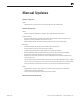
Manual Updates Updated 1 May 2009 Views: • Exploded Views: Corrected rear housing information for Mid 2009 model. Updated 28 April 2009 Basics: • Added section about differences between Early 2009 and Mid 2009 models. Troubleshooting: • General Troubleshooting: Added sections about Apple Hardware Test and Apple Service Diagnostic, how to determine which version to use. • Block Diagram: Added note that Mid 2009 model does not have IR or Bluetooth.
Apple Technician Guide Basics iMac (20-inch, Early/Mid 2009) © 2009 Apple Inc. All rights reserved.
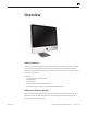
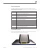
Overview Product Features The iMac (20-inch, Early 2009) and iMac (20-inch, Mid 2009) computers have the same overall look as the previous generation aluminum iMac. Distinguishing exterior features are Mini DisplayPort (instead of mini DVI port) and 4 USB ports (instead of 3) on the rear, and a tapered front edge on the stand. New features: • Increased processor speed: 2.66GHz • Mini DisplayPort • 4 USB 2.
Product Configuration To confirm the configuration from the Apple menu, choose About This Mac. The processor listing will show the speed of the processor followed by the processor type. The following table shows the configuration at introduction: Feature Specification Processor 2.
Apple Technician Guide Troubleshooting iMac (20-inch, Early/Mid 2009) © 2009 Apple Inc. All rights reserved.
General Troubleshooting Update System Software Important: Whenever possible before beginning troubleshooting, ensure the latest software and firmware updates have been applied. Firmware Updates Firmware is the name given to software that is written into memory circuits such as flash memory, that will hold the software code indefinitely, even when power is removed from the hardware. Firmware on Intel Mac computers is designed to be updated if necessary through a software update.
Apple Hardware Test There are two versions of Apple Hardware Test (AHT) for the iMac (20-inch, Early 2009). To identify which version of AHT to use, check the third, fourth, and fifth digits in the system serial number. See examples below. • Apple Hardware Test 3A156 to be used on systems with the third, fourth, and fifth serial number digits below 913.
Starting Up in Safe Mode A Safe Boot is a special way to start Mac OS X when troubleshooting. Safe Mode is the state Mac OS X is in after a Safe Boot: 1. Make sure the computer is shut down. 2. Press the power button. 3. Immediately after you hear the startup tone, press and hold the Shift key. Note: The Shift key should be held as soon as possible after the startup tone but not before. 4. Release the Shift key when you see the screen with the gray Apple and progress indicator (looks like a spinning gear).
Resetting the System Management Controller (SMC) The System Management Controller (SMC) is a chip on the logic board that controls all power functions for your computer. If your computer is experiencing any power issue, resetting the SMC may resolve it. The SMC controls several functions, including: • telling the computer when to turn on, turn off, sleep, wake, idle, and so forth; • handling system resets from various commands; and • controlling the fans. Note that resetting the SMC does not reset the PRAM.
Diagnostic LEDs The iMac has built-in diagnostic LEDs on the main logic board that can help you to troubleshoot the computer. The LEDs are located to the right of the battery (see photo below). LED #1 Indicates the trickle voltage from the power supply has been detected by the logic board. This LED will remain ON whenever the iMac is connected to a working AC power source. The LED will remain on even when the computer has been shut down or put to sleep.
Sensor and Fan Connector Locations Ambient temp sensor and fan connector locations are shown below. Ensure cables are correctly routed and the sensors and fans are properly connected. If a sensor or fan is faulty or not connected, Apple Hardware Test will generate an error code.
Block Diagram Refer to this diagram to see how modules are interrelated. Note the iMac (20-inch, Mid 2009) does not have IR or Bluetooth. 12V in 20” AC Inlet AC/DC Optical Drive Temperature Sensor SATA II Temperature Sensor Inverter Microphone Camera Hard Drive SATA II USB 2.0 ODD Fan Temperature Sensor Display HD Fan Temperature Sensor MLB USB 2.0 PCIe x1 USB 2.0 Antenna Power Button IR Sensor DDR3-1066 CPU Fan Speaker 2009-05-01 Ambient Temperature Sensor SO-DIMM Bluetooth 802.
Symptom Charts Follow the steps in the order indicated below. If an action resolves the issue, retest the system to verify. Note: A compilation of Quick Check tables is available at: http://service.info.apple.com/QRS/en/quickreference.
2. Remove front bezel and locate diagnostic LED’s on logic board. Plug power cord into system. Verify whether diagnostic LED #1 turns ON. Yes Trickle voltage being supplied by power supply. Go to step 3. No Replace power supply. 3. Press power button while monitoring diagnostic LED’s. Does diagnostic LED #2 turn ON and remain ON after pressing the power button? Yes Power supply functioning and logic board detects supply voltages. Jump to Won’t Start Up symptom flow. No Go to step 5. 4.
Won’t Start Up Quick Check Symptoms Quick Check Won’t Start Up • No startup chime. • Error tones during startup. • Grey screen with fan noise, or other noise. • Will not progress beyond Apple logo or spinning gear. 1. Isolate OS by starting up from original install media for the computer, the same make and model computer in Target Disk Mode, or compatible known-good OS on an external drive. Both AirPort and Bluetooth services are available when booted from the Install disk. 2.
3. Remove the coin battery on the logic board, and leave out for approximately 1 minute. Then reinstall the battery. This will reset the logic board. Does the computer startup properly now? Yes Issue resolved by logic board reset. Measure DC voltage on the battery touching the battery with the red probe, and grounding with the black probe. If voltage is 2.7v or less, replace the battery. See KBase article http://support.apple. com/kb/HT3250 for details on using a digital multi-meter. No Go to step 4.
Intermittent Shutdown Quick Check Symptoms Quick Check Intermittent Shutdown • Powers off during startup. • Powers off during desktop use. • Computer restarts spontaneously. • Powers off when waking from sleep. 1. Isolate OS by starting up from original Install media for the computer, the same model computer in Target Disk Mode, or compatible known-good OS on an external drive. Both AirPort and Bluetooth services are available when booted from the Install disc. 2.
2. With known-good AC power cord and AC outlet, does the unit continue to shutdown? Yes Go to step 3. No AC power cord/ outlet issue. Issue resolved. 3. Disconnect the hard drive power cable from the hard drive and start the machine from the Install DVD, the same make and model computer in Target Disk Mode, or compatible known-good OS on an external drive. Does the computer continue to shutdown? Yes Go to step 4. No Possible bad software or hard drive. Go to Hard Drive Not Recognized symptom flow.
Kernel Panic, System Crashes Quick Check Symptoms Quick Check Kernel Panic, System Crashes • Kernel panic on startup or desktop use. • System freeze during use. • System freeze upon wake from sleep. 1. Isolate OS by starting up system from original Install media for the computer, the same make and model computer in Target Disk Mode, or compatible known-good OS on an external drive. Both AirPort and Bluetooth services are available when booted from the Install disc. 2.
3. Use known-good SDRAM in the system. Does the computer start without kernel panic now? 2009-05-01 Yes Install user’s SDRAM and test. If kernel panic repeats, replace SDRAM. Verify that the correct SDRAM is being used. No Go to step 4. 4. Remove AirPort card and test. Does the computer start without kernel panic now? Yes Go to AirPort Card Kernel Panic symptom flow. No Go to step 5. 5.
No Video Unlikely cause: hard drive, optical drive, speakers, camera, microphone Quick Check Symptoms Quick Check No Video • No image. • Backlight failure. 1. Check brightness setting. 2. For no-video issues, connect an external display to verify whether iMac video circuitry is functioning. If image appears on external display go to Backlight Issue/No Backlight symptom flow. 3. Reset SMC. Deep Dive Check Result 1. Verify boot chime present and fans running when system powered ON.
Corrupted Video Unlikely cause: power supply, hard drive, optical drive, fans, speakers, camera, microphone Quick Check Symptoms Quick Check Corrupted Video • Text and graphics appear fuzzy • Image corrupted 1. Set System Preferences/Display LCD panel to native resolution. Non-native resolutions are unable to produce optimal clarity. 2. Make sure all relevant software updates have been applied. Graphics driver updates may be included with software updates. 3.
2009-05-01 3. Remove logic board, inspect connectors for damage or corrosion then reinstall. Verify whether issue still occurs. Yes Replace logic board. Go to step 4. M04 No Issue likely caused by poor connection. Return computer to user. M04 4. Verify whether issue is still present with replacement logic board installed. Yes Return to step 1 and retest. X04 No Issue resolved with replacement logic board. Return computer to user. M04 5.
Burnt Smell/Odor Unlikely cause: speakers, microphone, enclosure Quick Check Symptoms Quick Check Burnt Smell/Odor • Burning smell • Unusual odor 1. Verify source of smell/odor is emanating from the system. 2. If system is new refer to KBase article http://support.apple.com/kb/TA22044 for information on new computer odors. 3. Disconnect all third-party devices and confirm whether the odor is being generated by the device. 4. Inspect air intake and air outlets for obstructions.
3. Can the source of the odor be located using nose? Yes Replace affect module(s) and retest system. No Contact Apple for assistance if you feel that there is a possible safety issue with the computer that has not been resolved in the previous steps. P08 Uncategorized Symptoms Quick Check Symptoms Quick Check Uncategorized Symptoms • Unable to locate appropriate symptom code. 1. Make sure system is plugged into a known-good outlet. 2.
Display Backlight Issue/No Backlight Unlikely cause: hard drive, optical drive, speakers, camera, microphone Quick Check Symptoms Quick Check Backlight Issue/No Backlight • No image • Partial backlight failure • Backlight flickers • Display dim 1. Check System Preferences > Displays > Brightness control setting is above minimum. 2. For no-image issues connect an external display to verify whether iMac video circuitry is functioning. Go to No Video symptom flow if no image is visible on external display.
2009-05-01 4. Verify if LCD backlight is ON by looking for faint glow from display when viewed in darkened room with brightness set at maximum. Yes Internal LCD panel backlight is functioning. Go to step 6. No Go to step 5. 5. Shine bright (low heat) flashlight onto the front of the LCD. With the system powered ON verify whether a faint image is visible. Yes LCD panel functional but backlight is not ON.
Noise / Unstable Flickering Unlikely cause: camera, microphone Quick Check Symptoms Quick Check Noise / Unstable Flickering • Unstable image • Flickering image • Humming noise from display • High frequency noise from display 1. Verify that intake vent on the bottom of the system is not obstructed. 2. Inspect system for 3rd party software that is being used to set fan speeds to a higher than normal RPM.
4. Power ON system and verify whether the issue still occurs. 2009-05-01 Yes If connections are secure and the display is still flickering, go to step 5. No Issue was caused by a poor connection between display and logic board or inverter. Return computer to user. 5. Shine bright (low heat) flashlight into the front of the LCD. Verify if an image is being displayed when flickering issue is occurring. Yes Image present but backlight is flickering. Replace inverter then retest.
LCD Image Issues Unlikely cause: power supply, hard drive, optical drive, fans, speakers, camera, microphone Quick Check Symptom Quick Check LCD Issues • Incorrect/missing colors • Distorted/blurred image • Pixel anomalies • Vertical/horizontal lines • Non-uniform brightness 1. Allow display to reach normal operating temperature for about 15 minutes before evaluating front-of-screen performance. 2. Check display preferences for use of custom display profile. 3. Check brightness setting. 4.
Incorrect/Missing Colors Unlikely cause: power supply, hard drive, optical drive, fans, speakers, camera, microphone Quick Check Symptoms Quick Check Incorrect/Missing Colors • Wrong color display • Color/contrast issues 1. Allow display to reach normal operating temperature for about 15 minutes before evaluating front-of-screen performance. 2. Verify that System Preferences/Display settings are configured to use the default display profile. 3.
Distorted/Blurred Image Unlikely cause: power supply, hard drive, optical drive, fans, speakers, camera, microphone Quick Check Symptoms Quick Check Distorted/Blurred Image • Text and graphics appear fuzzy • Image corrupted 1. Set System Preferences/Display LCD panel to native resolution. Non-native resolutions are unable to produce optimal clarity. 2. Clean outside surface of glass panel using provided cleaning cloth. 3. Boot from install DVD to determine whether potential software issue exists.
2009-05-01 5. Remove LVDS cable from LCD panel and logic board and carefully verify whether there is damage to the cable or connectors. Yes Replace LVDS cable. No Reinstall LVDS cable. Go to step 6. 6. Verify whether issue is still visible after reinstalling LVDS cable. Yes Replace LCD panel. Go to step 7. No Issue resolved with replacement logic board. Return computer to user. 7. Verify whether issue is still present with replacement LCD panel installed. Yes Return to step 1 and retest.
Pixel Anomalies Unlikely cause: logic board, power supply, hard drive, optical drive, fans, speakers, camera, microphone Quick Check Symptoms Quick Check Pixel Anomalies • Dark dot anomalies • Bright dot anomalies • Debris on inside surface of glass panel • Debris on surface of LCD panel 1. Clean outside surface of glass panel using provided cleaning cloth. 2. For information about pixel anomalies, see kBase article: http://support.apple.com/kb/HT1721 Deep Dive Check 2009-05-01 Result Action 1.
Vertical/Horizontal Lines Unlikely cause: power supply, hard drive, optical drive, fans, speakers, camera, microphone Quick Check Symptoms Quick Check Vertical/Horizontal Lines • Vertical lines • Horizontal lines 1. Boot from install DVD to determine whether potential software issue exists. 2. Verify if issue is visible on an external display. Deep Dive Check 2009-05-01 Result Action Code 1. Boot from Install DVD and verify whether issue is still visible. Yes Go to step 2.
2009-05-01 6. Verify whether issue is still visible after reinstalling LVDS cable. Yes Replace LCD panel. Go to step 7. No Issue resolved with replacement logic board. Return computer to user. 7. Verify whether issue is still present with replacement LCD panel installed. Yes Return to step 1 and retest. No Issue resolved with replacement LCD panel. Return computer to user.
Non-Uniform Brightness Unlikely cause: power supply, hard drive, optical drive, fans, speakers, camera, microphone Quick Check Symptoms Quick Check Non-Uniform Brightness • Brightness not uniform • Color not-uniform 1. Verify System Preferences > Displays > Brightness level control is set above minimum. 2. Allow 15 minutes for backlight bulbs to reach normal operating temperature and output before evaluating display. 3.
Cosmetic Defects Quick Check Symptoms Quick Check Cosmetic Defects to LCD • Cracked LCD • Scratched LCD polarizer • Scorched or melted LCD • LCD impact damage • Foreign material on LCD or back side of glass panel. 1. Determine whether damage was caused by user environment, accidental damage, or abuse. If applicable, inform the user that Apple does not warrant damage caused by accident, abuse, misuse, flood, fire, earthquake, or other external causes. For more information refer to: http://www.apple.
Mass Storage Hard Drive Not Recognized Unlikely cause: LCD panel, power supply, fans, speakers, camera, microphone Quick Check Symptoms Quick Check Drive Not Recognized (H01) Drive No Boot (H02) • Flashing Question Mark • Boots to Grey Screen • Boots to Blue Screen 1. Use a known-good mouse. A stuck mouse button will not allow boot. 2. Boot from Install DVD. Verify S.M.A.R.T. status of drive using Disk Utility. 3. Repair disk using Disk Utility. 4. Erase disk and reinstall Mac OS using Install DVD. 5.
2009-05-01 5. Inspect hard drive SATA and power cables and connectors for bent pins, or other damage to the cable. Yes Replace damaged cable. Go to step 8. H04 No Go to step 6. 6. Reseat SATA and logic board hard drive connections and verify whether computer starts up. Yes Go to step 8. No Replace SATA cable. Go to step 8. 7. Test with known-good hard drive. Verify that system boots successfully and that Disk utility ‘Verify’ function reports no errors. Yes Install user drive. Go to step 9.
Hard Drive Read/Write Error Unlikely cause: LCD panel, power supply, fans, speakers, camera, microphone Quick Check Symptoms Quick Check Drive Read/Write Error (H03) Drive Bad Sector/Defective (H05) Drive Formatting Issues (H07) • Cannot save documents • Read/write error message • Hang when accessing or saving data 1. Boot from Install DVD. Verify S.M.A.R.T. status of drive using Disk Utility. 2. Repair disk using Disk Utility. 3. Erase disk and reinstall Mac OS using Install DVD. 4.
7. Reboot computer. Verify that system boots successfully and that Disk Utility ‘Verify’ function reports no errors. Yes Issue resolved. Return system to user. No Go to step 6. 8. Reboot computer. Verify that system boots successfully and that Disk Utility ‘Verify’ function reports no errors. Yes Issue resolved. No Hard drive appears to be defective Go to step 9. 9. Replace user hard drive.
2009-05-01 3. Restart the computer. Verify whether the noise is still present. Yes Go to step 6. No Data error issue resolved by Disk Utility. Return system to user. 4. Erase disk and reinstall Mac OS using Install DVD. Verify that installation process completes. Note: Make sure data has been backed up before erasing hard drive. Yes Go to step 3. No Replace hard drive. Go to step 5. 5. With replacement hard drive installed reboot computer. Verify whether noise is still present.
Optical Drive Not Recognized Unlikely cause: LCD panel, power supply, fans, speakers, camera, microphone Quick Check Symptoms Quick Check Drive Not Recognized/Mount (J05) • Discs inject and eject, but do not appear in Finder 1. Use Apple System Profiler Serial-ATA section to see if the optical drive and any inserted media appears. 2. Check Finder Preferences and make sure “CD’s, DVD’s and iPods” is checked under “Show these items on the desktop” in the General section. 3. Check both CD and DVD media.
5. Connect original optical drive to known-good SATA cable. Do both types of media reliably read now? Yes SATA cable issue. Replace SATA cable. Go to step 6. No Go to step 2. 6. Test read compatible knowngood CD and DVD media (Install DVD). Verify media is recognized and reads reliably. Yes Issue resolved. No Replace optical drive.
2009-05-01 3. Connect known-good optical drive to SATA cable. Verify that known-good optical drive is listed in the System Profiler device tree. Yes Go to step 4. No Suspect SATA cable. Go to step 7. 4. With known-good optical drive installed, test for media inject/ eject. Verify drive accepts and ejects known-good media. Yes Known-good optical drive resolved inject/eject issue. Replace optical drive. No Go to step 7. 5. Inspect optical drive slot during disc insert/ eject.
Optical Drive Read/Write Error Unlikely cause: LCD panel, power supply, fans, speakers, camera, microphone Quick Check Symptoms Quick Check Drive Read/Write Data Error (J03) • Errors when writing optical media. • Errors when reading optical media. • Hang when accessing or preparing to write data. 1. Test optical media in another drive of the same type in the same type of computer to rule out media issue. 2. Check with known-good discs like the Install discs that came with the computer. 3.
5. Connect original optical drive to known-good SATA cable. Do both types of media reliably read now? Yes SATA cable issue. Replace SATA cable. Go to step 6. X03 No Replace optical drive. J03 6. Test write data to compatible CD and DVD media. Verify burned media is recognized and reads reliably. Yes Issue resolved. No Replace optical drive.
3. Connect known-good optical drive to SATA cable. Do both types of media reliably read now? Yes SATA cable and port on logic board good. Go to step 5. No Replace SATA cable and test (X03). If issue persists, replace logic board (M19). Go to step 6. 4. Connect original optical drive to known-good SATA cable. Do both types of media reliably read now? Yes SATA cable issue. Replace SATA cable. Go to step 6. X03 No Replace optical drive. J03 5. Test write data to compatible CD and DVD media.
Deep Dive Check 2009-05-01 Result Action Code 1. Test both CD and DVD media. Can drive read both CD media and DVD media? Yes Go to step 6. No Drive has a laser issue. Replace the optical drive. If both types media fail, go to step 3. 2. Reseat SATA cable connections at logic board and optical drive. Do both types of media read reliably now? Yes Go to step 6. No Go to step 4. 3. Connect known-good optical drive to SATA cable.
Uncategorized Symptoms Check Result 1. Verify whether existing symptom code applies to the issue reported by the user. 2009-05-01 Action Yes Jump to appropriate symptom code flow. No Document reported failure and send feedback to smfeedback6@apple.com stating that a suitable symptom code wasn’t found. Provide as much detail as possible.
Communications AirPort/Bluetooth Issues Quick Check Symptoms Quick Check AirPort/Bluetooth Issues • Unable to join networks or pair devices • AirPort card not available • Intermittent device or connection dropouts • Limited wireless range 1. Verify that AirPort or Bluetooth is turned ON and for AirPort issues make sure that a network is selected. 2. For AirPort, check if the wireless access point requires special connection and encryption protocols. 3.
2009-05-01 2. Ensure that antenna cable(s) are connected properly and not damaged, and all software updates available for AirPort/ Bluetooth have been installed. Do connection issues persist? Yes AirPort, go to step 3. Bluetooth, go to step 4. No Issue resolved. 3. Create a computer-tocomputer network with another Macintosh computer using AirPort. See kBase article http://docs.info.apple.com/ article.html?path=AirPort/5.0/ en/ap2110.html. Can you connect successfully? Yes Network or channel issue.
AirPort Card Kernel Panic Quick Check Symptoms Quick Check AirPort Card Kernel Panic • Kernel panic on startup • Kernel panic or freezing while attempting to connect to wi-fi networks • Kernel panic while transferring data on wi-fi networks 1. Isolate OS by starting up from original Install media for the computer, the same model computer in Target Disk Mode, or compatible known-good OS on an external drive. AirPort service is available when booted from the Install disc. 2.
Ethernet Port/Device Issue Unlikely cause: LCD display, power supply, hard drive, optical drive, fans Quick Check Symptoms Quick Check Ethernet Port/Device Issue • No ethernet device present • Unable to access network resources • Ethernet device shows no connection • Ethernet device unable to an IP address • Slow network performance 1. Check the ethernet cable for damage, try a known-good ethernet cable – CAT5 or better recommended for 100Mbps+ connections. 2.
3. Connect the computer to another Macintosh computer using CAT5 ethernet cable. See kBase article http:// docs.info.apple.com/article. html?path=Mac/10.5/en/8429. html. Can you connect successfully? Yes Ethernet communication good. Go to step 4. No If same ethernet cable and computer connects to a known-good computer of same model, replace logic board. 4. Check for speed and duplex issues on the network. Open System Preference > Network; click the Advanced button, then the Ethernet tab.
Deep Dive Check 2009-05-01 Result Action 1. Without any wired input devices connected, start the computer. Does the computer show the Bluetooth Mouse Setup assistant? Yes Bluetooth hardware is active. Go to step 4. No Inspect and reseat Bluetooth cable to Bluetooth card. Replace a damaged cable. Go to step 2. 2. Restart the machine without any wired input devices attached. Does the computer show the Bluetooth Mouse Setup assistant? Yes Bluetooth hardware is active. Go to step 4.
Wireless Input Device Loses Connection Quick Check Symptoms Quick Check Wireless Input Device Loses Connection • Wireless keyboard, mouse, or other wireless input device loses connection. 1. Remove and reinstall the batteries for the device. 2. Check that device is powering on. 3. Use known-good batteries with the device. 4. Ensure other devices pair and keep connection without issue. If not, go to AirPort/Bluetooth Issues symptom flow. 5.
2009-05-01 5. Log into new Admin User account. With the device on, run the Bluetooth Setup Assistant. Can you successfully pair the device with the New User? Yes User-based issue. Troubleshoot software on User account. No repair needed. No Remove the following file: / Library/Preferences/com. apple.Bluetooth.plist Go to step 6. 6. Restart the computer. With the device on, run the Bluetooth Setup Assistant. Can you successfully pair the device? Yes Go to step 7.
Uncategorized Symptoms Quick Check Symptoms Quick Check Uncategorized Symptoms • Unable to locate appropriate symptom code. 1. Verify System Preferences/Network settings are configured appropriately to support communication method. 2. For ethernet connection issues verify that the cable being used functions when used with another known-good system. 3. For wireless connection issues review user environment to determine whether possible interference from other 2.
Input/Output Devices Apple Remote Inoperable Unlikely cause: LCD display, power supply, hard drive, optical drive, fans Quick Check Symptoms Quick Check Apple Remote Inoperable • Apple Remote doesn’t bring up Front Row • Apple Remote doesn’t control iTunes • Apple Remote doesn’t control computer volume 1. Make sure you’re using the Apple Remote within 30 feet of the computer, and have an unobstructed line-of-sight to the computer. 2.
4. After clicking “Unpair”, does the computer now respond to the Apple Remote? Yes Pairing issue. Issue resolved. No Possible IR board issue. Go to step 5. 5. Open the Apple System Profiler. Selecting USB, do you see “IR Receiver” listed? Yes IR Receiver reporting on USB bus. Check for lens block. Go to step 6. No Inspect and reseat IR cable to IR board. If necessary, replace damaged IR cable. Go step 7. 6. After clearing lens, does the computer now respond to the Apple Remote? Yes Lens blocked.
Deep Dive Check 2009-05-01 Result Action Code 1. Verify that boot chime is present when system is powered on. Note: make sure audio output preferences are not set to mute. Yes Go to step 2. No Audio board not detected by system. Reseat audio board, then replace audio board if problem persists. 2. Launch System Preferences and select Sound/Input options. Verify that system’s Internal Microphone is selected. Yes Go to step 3. No Select display’s internal microphone. Retest. 3.
Audio: Built-in Speakers Have Distorted Sound Unlikely cause: LCD display, power supply, hard drive, optical drive, fans Quick Check Symptoms Quick Check Audio: Built-in Speakers Have Distorted Sound • No audio from one or both speakers • Audio from speakers distorted 1. Launch System Preferences and select Sound/ Output options. Verify that the sound output option is set to system’s internal speakers and the balance control is set to the center position. 2.
4. Inspect LEFT and RIGHT speaker cones and speaker connection cable for damage. Do speakers have visible damage? Yes Replace damaged speaker. Retest. M09 No Go to step 5. 5. Install known-good speaker into location where distorted sound was heard. Verify that sound quality improves. Yes Speaker bad. Replace speaker and retest. M09 No Suspect speaker amplifier. Replace audio board.
2009-05-01 2. Launch System Preferences and select Sound/Output options. Set speaker balance 100% to LEFT speaker then play a sound file. Verify that sound is generated by the LEFT speaker and that the sound quality is acceptable. Yes LEFT speaker and amplifier circuitry OK. Go to step 3. No Go to step 6. 3. Set speaker balance 100% to RIGHT speaker then play a sound file. Verify that sound is generated by the RIGHT speaker and that the sound quality is acceptable.
Camera Issues Unlikely cause: LCD display, power supply, hard drive, optical drive, fans, speakers, microphone Quick Check Symptoms Quick Check Camera Issues • Camera not detected • No green LED for camera • Excessive blooming • Poor white balance • Poor focus • Green image • Image distortion 1. Launch System Profiler and confirm that system’s USB hub and built-in camera are visible. 2. Verify camera lens and glass panel are clean and free of contaminants.
FireWire Devices Not Recognized Unlikely cause: LCD display, power supply, hard drive, optical drive, fans Quick Check Symptoms Quick Check FireWire Devices Not Recognized • FireWire external drive not recognized • FireWire printer not recognized 1. For external FireWire drives, make sure any external power source is plugged in and operating to isolate a power issue with the device. 2. Test with a known-good FireWire device to isolate a failed peripheral issue. 3.
2009-05-01 4. Is the FireWire device recognized with a known-good FireWire cable on the user’s computer? Yes FireWire cable issue. Issue resolved. No FireWire device may need additional power. Use a powered FireWire hub. If the issue persists, check for any firmware updates for the FireWire device. Go to step 5. 5. Using a powered FireWire hub, and having installed any software or firmware update for the device, is the FireWire device recognized now? Yes Device recognized.
USB Devices Not Recognized Unlikely cause: LCD display, power supply, hard drive, optical drive, fans Quick Check Symptoms Quick Check USB Devices Not Recognized • USB wired keyboard/mouse not recognized • USB external drive not recognized • USB printer not recognized 1. For printers and external USB drives, make sure any external power source is plugged in and operating to isolate a power issue with the device. 2. The iMac has 4 USB ports on the rear of the computer.
3. Are known-good mouse and keyboard recognized? 2009-05-01 Yes Test original mouse and keyboard. Replace if still not recognized. Go to step 5. No External USB ports not functioning. Replace logic board. 4. With no USB devices connected, restart the computer. Did Bluetooth Mouse Setup assistant launch after startup? Yes Bluetooth detected via Internal USB. Go to step 3. No Bluetooth not recognized via internal USB. Internal and external USB not functioning. Replace logic board. 5.
Wired Keyboard Does Not Function Properly Unlikely cause: LCD display, power supply, hard drive, optical drive, fans Quick Check Symptoms Quick Check Wired Keyboard Does Not Function Properly • Some or all keys on the keyboard don’t work • Eject key or Caps Lock key doesn’t seem to work • Some keys don’t work as expected 1. The iMac has 4 USB ports on the rear of the computer. Make sure to try each port to isolate a particular port malfunction. 2.
4. Open System Preferences > Speech. Is “Speak selected text when the key is pressed” enabled? Yes The key combination to speak text cannot be used for any other purpose. Either disable or change to a more rare key combination (including Shift, Command, Option and Control). No Go to step 6. 5. With optical media in the drive, hold the Media Eject key. Does the disc eject normally and the eject symbol appear? Yes Media Eject key delay. No repair necessary.
Keyboard: Specific Keys Do Not Respond Unlikely cause: LCD display, power supply, hard drive, optical drive, fans Quick Check Symptoms Quick Check Keyboard: Specific Keys Do Not Respond • One or more keys do not respond when pressed • Key sticks • Keycap missing 1. If wireless keyboard is being used verify that it is properly paired with the system. Jump to Wireless Input Device Doesn’t Pair symptom flow to resolve pairing issues. 2.
Deep Dive Check Result 1. Does the computer recognize at all the keyboard or mouse when plugged into the rear USB ports on the back of the iMac? Yes Test in all USB ports to ensure all USB ports working as expected. Replace logic board for any rear port failures. Replace keyboard for any keyboard USB port failures. Go to step 2. No Go to USB Devices Not Recognized symptom flow. 2. Is keyboard working as expected? Yes Go to step 3. No Go to Wired Keyboard Does Not Function Properly. 3.
Uncategorized Symptoms Quick Check Symptoms Quick Check Uncategorized Symptoms • Unable to locate appropriate symptom code. 1. Verify that external I/O device (where applicable) works on another system. 2. For third party I/O devices make sure necessary software is installed and up to date, and that the device is supported with the user’s system. Deep Dive Check Result 1. Verify whether existing symptom code applies to the issue reported by the user.
Mechanical Noise/Hum/Vibration Unlikely cause: LCD panel, glass panel, enclosure, cables Quick Check Symptoms Quick Check Noise/Hum/Vibration • Buzzing noise • Rattling noise • Ticking noise • Squeaking noise 1. Verify the vents on the bottom and back of the computer are free of dust and other obstructions that might inhibit proper airflow. 2. Launch Applications/Utilities/Activity Monitor. Determine whether an application or process is consuming a high percentage of CPU bandwidth.
Deep Dive Check Result 1. Run Apple Hardware Test from system or Install DVD. Did AHT generate any errors? Yes Go to Apple Hardware Test (AHT) Error Codes table to decode error. Follow instructions in table for resolving error, then retest. No Go to step 2. Yes Reset SMC by disconnecting power cord for ~15 seconds, then retest. If issue continues go to step 3. No Go to step 5. Yes Suspect issue with optical drive or the media being used.
2009-05-01 7. Reinstall fans while carefully ensuring that there are no cables routed under or near fan assembly that might cause interference with the fan blades. After reassembling system verify that the noise issue is resolved. Yes Noise issue resolved. Suspect issue cause by interference from wiring or possible distortion or fan housing when installed in system. Proper reassembly resolved issue. No Go to step 8. 8. Temporarily remove LCD display then power ON system.
Fan Failures / Thermal Issues Unlikely cause: speakers Quick Check Symptoms Quick Check System Runs Hot • System feels very hot • Fan(s) not operating • Fan(s) running fast • System is noisy 1. Verify the vents on the bottom and back of the system are free of dust and other obstructions that might inhibit proper airflow. 2. Verify the computer is not exposed to direct sunlight which may heat up the enclosure, making it feel hot to the touch. 3.
Does noise sound like one or more fans running faster than expected? Remove fans and rotate the blades. Verify that fan blades spin smoothly without interference from fan housing and that the fan blades are all intact. Yes Fans running fast. Reset SMC by disconnecting power cord for ~15 seconds then retest. If issue continues go to step 3. No Go to step 3. Yes Go to step 7. No Replace affected fan(s).
Uncategorized Symptoms Check 1. Verify whether existing symptom code applies to the issue reported by the user. 2009-05-01 Result Action Yes Jump to appropriate symptom code flow. No Document reported failure and send feedback to smfeedback6@apple.com stating that a suitable symptom code wasn’t found. Provide as much detail as possible.
Apple Technician Guide Take Apart iMac (20-inch, Early/Mid 2009) © 2009 Apple Inc. All rights reserved.
General Information General Tools The following tools are required to service the computer: • ESD-safe workstation, including an ESD mat and wrist or heel strap • ESD bags • Magnetized Torx T10 screwdriver • Magnetized Torx T8 screwdriver • Magnetized Torx T6 screwdriver • Magnetized Phillips #2 screwdriver • Black stick (nylon probe, Apple part #922-5065) or other non-conductive nylon or plastic flat-blade tool • EMI tape (Apple part #922-8691) • Soft, clean towel or cloth (to protect the display and remov
Cleaning Tools Starter Kit The following tools are offered in the starter kit (076-1277): • Suction cups, 1 pair • Gloves, lint-free, anti-static, 2 pairs • Sticky silicone roller (6-inch) to clean the glass panel • Sticky sheets to clean the silicone roller, 2 pads • Polishing cloths, clean, anti-static, optical-grade micro-fiber “terry” style, 5 cloths • Microfoam bag to store the glass panel, 5 bags • ESD bag for LCD panel storage, 5 bags Cleaning Tool Resources Note: Apple Retail technicians should ref
Cleaning & Handling the Glass Panel Follow the cleaning procedures in this manual to ensure the glass panel is free of dust and other particles before returning the computer to the customer. • The glass panel is not tempered and will break into sharp pieces of mishandled. A scratched or broken glass panel is not covered under warranty. • Removing the glass panel requires special tools such as lint-free gloves, rubber suction cups, microfoam storage bags, and the iKlear cleaning solution.
Safety Warning: HIGH VOLTAGE: The AC/DC power supply PCB remains powered up whenever the system is plugged in, whether or not the system has been turned on. Use extreme caution when troubleshooting the system with the front bezel removed. • Don’t work alone. In the event of an electrical shock it is important to have another individual present who can provide assistance. • Keep one hand in your pocket when working on any iMac system that is plugged in.
Logic Board Handling IMPORTANT: Always use two hands to support the logic board and heatsink. Handling the board incorrectly could flex the board and damage the chips and circuitry. Never handle the board by the heatsink.
ESD Precautions Static electricity, a normal and natural phenomenon, builds up on your body as you walk around. In fact, static electricity is created any time two dissimilar materials rub against each other (such as shoes and carpet) and then pull apart. The word “static” simply means that the electrical charge builds up on one of the two materials because it has nowhere to go.
all Apple replacement modules in their ESD-safe packaging until you need them. 7. Do not wear polyester clothing or bring plastic, vinyl, or Styrofoam into the work environment. The electro-static field surrounding these materials can’t be totally removed. 8. If possible, keep the humidity in the service area between 70% and 90%, and use an ion generator. Charge levels are reduced (but not eliminated) in high-humidity environments.
Access Door First Steps • • • • • Shut down computer. Wait 10 minutes. Unplug all cables and the power cord. Put on ESD strap. Place computer face down on a clean, soft, lint-free cloth so the bottom is facing you. Tools • • • ESD wrist strap Clean, lint-free cloth Phillips #2 screwdriver Removal 1 Loosen captive Phillips #2 screw. 2 Remove access door (922-8186).
Memory First Steps Remove: • Access Door Tools • • • ESD wrist strap Clean, lint-free cloth Black stick 2009-05-01 iMac (20-inch, Early/Mid 2009) Take Apart — Memory 98
Removal 1 Untuck tab in memory compartment (a black stick can help) and pull it to eject installed memory module. Reassembly 1 Orient notch on memory module with notch in memory slot. 2 Press memory module fully into slot until you hear a click. 3 Fold black plastic tab over each memory module. 4 Replace access door and tighten captive screw.
Glass Panel First Steps • • • • Shut down computer. Wait 10 minutes. Unplug all cables and the power cord. Put on ESD strap. Caution: The glass panel is not tempered and will break into sharp pieces if mishandled. A scratched or broken glass panel is not covered by warranty. How to handle a broken glass panel Important: This procedure requires special tools, which are offered individually or as part of a cleaning kit.
Removal Glass panel is held in place by magnets in front bezel. 1 Lay computer on its back and press clean suction cups in opposite corners on glass panel. Apple strongly recommends wearing clean, lint-free gloves whenever handling the glass panel, to reduce cleaning required on reassembly. Handling and cleaning tips for the glass panel. 2 Lift panel straight up and off.
3 Remove suction cups and slide glass into protective microfoam bag (922-8259). Reassembly 1 Remove protective covering from silicone roller and sticky sheet. 2 Clean silicone roller by rolling it back and forth a few times on sticky sheet. If sticky sheet looks dirty, use a new one. If roller is no longer tacky, wash it in warm soapy water. If tackiness does not return, replace silicone roller.
3 Wearing clean gloves, set display in upright position to minimize settling of dust. 4 Roll silicone roller over LCD panel to remove any particles. 5 Remove glass panel from microfoam bag. 6 Clean INSIDE of glass panel with the silicone roller to remove dust. Note: If fingerprints or oils are on inside of glass, clean first with isopropyl alcohol.
7 Note alignment pins on inside of glass panel. Caution: Pins can break off if glass panel is removed or installed at an improper angle. 8 Wearing clean gloves, place glass directly onto unit. Magnets will catch it and hold it in place. Make sure the glass is flush with the rear housing after it is reinstalled.
9 Clean outside of glass panel with a clean microfiber cloth. If necessary, use a small amount of iKlear polish. Wipe glass until there is no longer any residue or haze. 10 Once glass has been cleaned and polished, inspect glass for any remaining dust, fingerprints, or a hazy residue. If there are contaminants trapped between LCD panel and glass panel, repeat cleaning procedure above before returning unit to user.
Front Bezel First Steps Remove: • Access Door • Glass Panel Tools • • ESD wrist strap Torx T8 screwdriver 2009-05-01 iMac (20-inch, Early/Mid 2009) Take Apart — Front Bezel 106
Removal 1 Lay computer down with rear cover and stand on a soft, protective surface. 2 Remove T8 screws: (8) 922-8206, 13mm (4) 922-8207, 25mm Reassembly Note: The 4 longer screws attach along bottom of bezel. 3 Slowly lift bezel from top, without straining microphone cable.
4 Unwrap any Kapton tape and disconnect microphone cable from cable extension at top of front bezel. 5 Lift front bezel off rear housing. Reassembly Note: Secure bottom part of front bezel first and then lower top part, the reverse of the action shown here.
Camera First Steps Remove: • Access Door • Glass Panel • Front Bezel Tools • • ESD wrist strap Torx T8 screwdriver 2009-05-01 iMac (20-inch, Early/Mid 2009) Take Apart — Camera 109
Removal 1 Remove T10 screws: (2) 922-8850 2 Lift camera bracket out of rear housing. 3 Unwrap Kapton tape covering camera cable and connector. 4 Disconnect camera cable from camera board.
Battery First Steps Remove: • Access Door • Glass Panel • Front Bezel Tools • • ESD wrist strap Black stick 2009-05-01 iMac (20-inch, Early/Mid 2009) Take Apart — Battery 111
Removal 1 Use a black stick to pry battery from battery socket on logic board. Reassembly 1 Make sure battery socket is open and free of dust. 2 Press battery (9228892) into socket with engraved markings (+ side) facing up.
IR (Infrared) Board (Early 2009) First Steps Remove: • Access Door • Glass Panel • Front Bezel Note: iMac (20-inch, Mid 2009) model does not have an IR Board.
Removal 1 Remove T6 screws: (2) 922-8579 2 Disconnect IR cable (922-8832) from logic board. 3 Lift IR board and cable off logic board. Replacement Note: If installing a new IR board, transfer IR cable from old board to new board.
AirPort Extreme Card First Steps Remove: • Access Door • Glass Panel • Front Bezel Tools • • ESD wrist strap Torx T6 screwdriver 2009-05-01 iMac (20-inch, Early/Mid 2009) Take Apart — AirPort Extreme Card 115
Removal 1 Remove T6 screw: (1) 922-8579 2 Disconnect 2 antenna cables. Note: The antenna cables and connectors are very delicate and should be carefully removed by pulling on the connector rather than the cable. If an antenna cable is damaged, replace rear housing. Reassembly Note: Either cable can be attached to either connector with no change in performance. 3 Hold AirPort card by edges and pull it out of the slot.
Bluetooth Board (Early 2009) First Steps Remove: • Access Door • Glass Panel • Front Bezel Note: iMac (20-inch, Mid 2009) model does not have a Bluetooth Board.
Removal 1 Remove T6 screw: (1) 922-8579 2 Disconnect blue antenna cable. Note: The antenna cable and connector are very delicate and should be carefully removed by pulling on the connector rather than the cable. If the antenna cable is damaged, replace rear housing. 3 Disconnect black cable (922-8836) from logic board. 4 Lift Bluetooth board off logic board. Replacement Note: If installing a new Bluetooth board, transfer black cable from old board to new board.
LCD Panel First Steps Remove: • Access Door • Glass Panel • Front Bezel Tools • • • • • ESD wrist strap lint-free gloves Torx T6 screwdriver Torx T8 screwdriver ESD bag to store LCD panel 2009-05-01 iMac (20-inch, Early/Mid 2009) Take Apart — LCD Panel 119
Removal 1 Remove T6 screws from LVDS connector: (2) 922-8579 2 Remove T8 screws: (8) 922-8172 3 Disconnect LCD temp sensor cable from bottom left of the logic board. 4 Disconnect LVDS cable from right side of the logic board by pulling on black tab.
5 Grasp LCD panel at bottom edge and slowly tilt up. 6 Disconnect 4 inverter cable connectors on right side under LCD panel. Note: Pull connectors straight out. DO NOT pull on wires. Reassembly Note: Tuck inverter cables into open cavities in rear housing. Otherwise LCD panel may not lower into place correctly. 7 Lift LCD panel up and off rear housing.
Replacement Note: If installing a new LCD panel, disconnect LVDS cable and transfer to new panel. Secure with black cable stays. A replacement LCD panel includes display temp sensor cable & retaining clip, mounting brackets, foam strips & gaskets, and 2 black cable stays. Reassembly Note: Image at right shows a map of connectors on bottom left of logic board. LCD temp sensor cable connects to the center bottom of the 4 connectors.
LVDS Cable First Steps Remove: • Access Door • Glass Panel • Front Bezel • LCD Panel Tools • ESD wrist strap 2009-05-01 iMac (20-inch, Early/Mid 2009) Take Apart — LVDS Cable 123
Removal 1 Lay LCD panel face down on a clean, soft cloth. 2 Peel up 2 strips of black tape from LVDS cable on back of LCD panel. Save strips for use when reinstalling. 3 Remove clear tape from LVDS cable where it attaches to LCD panel. 4 Disconnect LVDS cable by pressing in on the side release clips (1) and then gently pull down (2).
Hard Drive First Steps Remove: • Access Door • Glass Panel • Front Bezel • LCD Panel Tools • • ESD wrist strap Torx T10 screwdriver (only needed if installing a new replacement hard drive) 2009-05-01 iMac (20-inch, Early/Mid 2009) Take Apart — Hard Drive 125
Removal 1 Disconnect hard drive temp sensor cable from top of logic board. Replacement Note: If installing a new hard drive, also peel back foam and disconnect temp sensor cable. Save cable to install on new hard drive, which will include the clip and a new foam gasket. 2 Release black plastic clip (922-8854): (1) rotate clip towards hard drive; and (2) swing clip up towards optical drive.
3 Slide pin of black plastic clip out of hole in chassis frame. Reassembly Note: Insert pin in hole and lower retaining clip until it snaps into second hole. 4 Lift hard drive up slightly to disconnect power and data cables from hard drive.
5 Slide 2 pins on the side of hard drive out of 2 rubber grommets in chassis, and remove hard drive assembly from computer. 6 If installing a new hard drive, transfer the following to the replacement drive: temp sensor cable (2) T10 screws 922-8580 • • • (2) T10 pins 922-7001 The screw pins go on the side closest to the power & data cable connectors.
Hard Drive Sensor Cable First Steps Remove: • Access Door • Glass Panel • Front Bezel • LCD Panel Tools • ESD wrist strap 2009-05-01 iMac (20-inch, Early/Mid 2009) Take Apart — Hard Drive Sensor Cable 129
Removal 1 Disconnect temp sensor cable from its connector on top of logic board. 2 Peel back foam gasket on top of hard drive and disconnect sensor cable from retaining clip (9228183). Note: Image at right shows a map of connectors on top of logic board. Hard drive sensor cable connects to the furthest left of the 3 connectors. Hard drive sensor has a 3-pin connector. Optical drive sensor has a 2-pin connector. Hard drive fan has a 4-pin connector.
Optical Drive First Steps Remove: • Access Door • Glass Panel • Front Bezel • LCD Panel Important: When servicing optical drive, handle it by edges only. Pressing elsewhere on drive could damage internal mechanism.
Removal 1 Remove T10 machine screws: (2) 922-6842 2 Carefully peel back strip of EMI mesh tape from rear housing. Reassembly Notes: Make sure EMI mesh does not cover any of the slot-load opening on rear housing. Also, make sure 4 inverter cables do not get trapped under optical drive. 3 Wiggle optical drive data cable connector away from optical drive. A black stick may be helpful.
4 Disconnect temp sensor cable from connector on top edge of logic board. 5 Lift optical drive out of rear housing. Warning: Handle optical drive by the edges only! Pressing or squeezing elsewhere could damage its internal mechanism. Replacement Note: If installing a new optical drive, peel back foam gasket and disconnect temp sensor cable from retaining clip on reverse side of drive.
Optical Drive Sensor Cable First Steps Remove: • Access Door • Glass Panel • Front Bezel • LCD Panel • Optical Drive Tools • ESD wrist strap 2009-05-01 iMac (20-inch, Early/Mid 2009) Take Apart — Optical Drive Sensor Cable 134
Removal 1 On reverse side of optical drive, peel back foam gasket and remove temp sensor cable (922-8827) from retaining clip (9228183). Note: Image at right shows a map of connectors on top of logic board. Optical drive sensor cable connects to the middle one of the 3 connectors. Hard drive sensor has a 3-pin connector. Optical drive sensor has a 2-pin connector. Hard drive fan has a 4-pin connector.
Optical Drive Fan First Steps Remove: • Access Door • Glass Panel • Front Bezel • LCD Panel Tools • ESD wrist strap 2009-05-01 iMac (20-inch, Early/Mid 2009) Take Apart — Optical Drive Fan 136
Removal 1 Disconnect cable from logic board. 2 Lift fan off 3 guide posts in the rear housing.
Optical Drive Data Cable First Steps Remove: • Access Door • Glass Panel • Front Bezel • LCD Panel • Optical Drive • Optical Drive Fan Tools • ESD wrist strap 2009-05-01 iMac (20-inch, Early/Mid 2009) Take Apart — Optical Drive Data Cable 138
Removal 1 Disconnect cable from logic board above audio board. 2 Lift cable from adhesive securing it to rear housing.
Inverter First Steps Remove: • Access Door • Glass Panel • Front Bezel • LCD Panel • Optical Drive Tools • • ESD wrist strap Torx T10 screwdriver 2009-05-01 iMac (20-inch, Early/Mid 2009) Take Apart — Inverter 140
Removal 1 Remove T10 screws: (2) 922-8251 2 Disconnect inverter power connector (pull in direction of hard drive). 3 Lift inverter cover and inverter board out of rear housing.
Power Supply First Steps Remove: • Access Door • Glass Panel • Front Bezel • LCD Panel Warning: HIGH VOLTAGE: Use extreme caution when working around the power supply, which contains a high-voltage capacitor that may remain charged for several minutes even when the computer is unplugged. Never touch the leads on the top side of the power supply, especially those near the warning sign.
Removal 1 Remove T10 screws: (2) 922-6800, self-tap (2) 922-6842, machine Reassembly Note: Install self-tapping screws on left side and machine screws on right side. 2 • • • 3 Disconnect 3 cables: large DC power supply cable small 2-pin ground connector AC inlet cable (protruding from pressure wall) Lift power supply out of rear housing.
Reassembly Note: Make sure pressure wall is in place. If it was removed, slip pressure wall over 2 posts on chassis and replace 2 screws.
Left Speaker First Steps Remove: • Access Door • Glass Panel • Front Bezel • LCD Panel Tools • • ESD wrist strap Torx T10 screwdriver 2009-05-01 iMac (20-inch, Early/Mid 2009) Take Apart — Left Speaker 145
Removal 1 Remove T10 screw: (1) 922-8249 2 Disconnect speaker cable from audio board. Reassembly Note: Tuck speaker cable under cable clip on CPU fan and route as shown. 3 Lift speaker up and out of computer.
Ambient Temp Sensor Cable First Steps Remove: • Access Door • Glass Panel • Front Bezel Tools • ESD wrist strap 2009-05-01 iMac (20-inch, Early/Mid 2009) Take Apart — Ambient Temp Sensor Cable 147
Removal 1 Disconnect ambient temp sensor cable (922-8826) from logic board. 2 Release cable from retaining clip on side of CPU fan. Note: Image at right shows a map of connectors on bottom left of logic board. Ambient temp sensor cable connects to the furthest left of the 4 connectors.
CPU Fan First Steps Remove: • Access Door • Glass Panel • Front Bezel • LCD Panel • Left Speaker • Ambient Temp Sensor Cable Tools • ESD wrist strap 2009-05-01 iMac (20-inch, Early/Mid 2009) Take Apart — CPU Fan 149
Removal 1 Disconnect cable from logic board near memory slots. 2 Lift fan straight up and off 3 guideposts in rear housing. Note: Image at right shows a map of connectors on bottom left of logic board. CPU fan cable connects to the furthest right of the 4 connectors.
Right Speaker First Steps Remove: • Access Door • Glass Panel • Front Bezel • LCD Panel Tools • • ESD wrist strap Torx T10 screwdriver 2009-05-01 iMac (20-inch, Early/Mid 2009) Take Apart — Right Speaker 151
Removal 1 Remove T10 screw: (1) 922-8208 2 Disconnect cable from audio board. 3 Lift speaker up and out of computer.
Audio Board First Steps Remove: • Access Door • Glass Panel • Front Bezel • LCD Panel • Right Speaker Tools • • ESD wrist strap Torx T6 screwdriver 2009-05-01 iMac (20-inch, Early/Mid 2009) Take Apart — Audio Board 153
Removal 1 • • • Disconnect 3 cables: left speaker (5-pin) microphone (3-pin) audio-to-logic board (922-8835) Right speaker cable (4-pin) should have been previously disconnected.
3 Remove EMI tape on back side of board. 4 Lift audio board off logic board.
Logic Board First Steps Remove: • Access Door • Glass Panel • Front Bezel • LCD Panel • Right Speaker Note: The iMac (20-inch, Mid 2009) does not have an IR Board or Bluetooth Board. Note: The audio board is part of the logic board. If returning logic board to Apple, make sure audio board is attached to old logic board.
Removal 1 Disconnect 16 cables from logic board. 1. hard drive temp 2. optical drive temp 3. hard drive fan 4. ambient temp 5. power button 6. CPU fan 7. power 8. hard drive data 9. AirPort antenna 10. AirPort antenna 11. camera (routes over, not under, the logic board.) 12. Bluetooth antenna (Early 2009 only) 13. left speaker 14. microphone 15. optical drive fan 16.
4 Lift logic board up and out of rear housing. Important: Always handle logic board by edges of circuit board only. Never handle by heatsink or metal frame! Reassembly If you removed logic board to access another module, reassembly is an exact reversal of the steps. If installing a new replacement logic board, note 4 things: 1 Verify that tamper indicator labels on front and back of heatsink assembly are intact. If labels have been removed or tampered with, the logic board is not eligible for exchange.
2 • • • • Transfer the following items from old logic board to new logic board: memory DIMMs AirPort card For the Early 2009 model, also transfer: Bluetooth board and cable IR board and cable 3 Replace 2 pieces of EMI tape onto I/O ports and rear housing as shown. The EMI tape is included in the box with a new logic board. 4 Important: Make sure to return old logic board with audio board attached.
Handling Logic Boards 1 IMPORTANT: Always use 2 hands to support logic board and heatsink. Handling board incorrectly could flex board and damage chips and circuits. 2 Never handle board by heatsink.
Hard Drive Fan First Steps Remove: • Access Door • Glass Panel • Front Bezel • LCD Panel • Right Speaker • Logic Board Tools • ESD wrist strap 2009-05-01 iMac (20-inch, Early/Mid 2009) Take Apart — Hard Drive Fan 161
Removal 1 Lift fan straight up and off the 3 guideposts. Note: Image at right shows a map of connectors on top of logic board. Hard drive fan cable connects to the furthest right of the 3 connectors. Hard drive sensor has a 3-pin connector. Optical drive sensor has a 2-pin connector. Hard drive fan has a 4-pin connector.
Hard Drive Data Cable First Steps Remove: • Access Door • Glass Panel • Front Bezel • LCD Panel • Right Speaker • Hard Drive • Logic Board Removal 1 Remove clear tape securing cable to chassis. 2 Lift cable out of computer.
Mechanism Cover First Steps Remove: • Access Door • Glass Panel • Front Bezel • LCD Panel • Right Speaker • Logic Board • Hard Drive • Hard Drive Fan Removal 1 Peel up EMI tape from top and bottom of mechanism cover. 2 Lift cover off mechanism. .
Stand First Steps Remove: • Access Door • Glass Panel • Front Bezel • LCD Panel • Right Speaker • Logic Board • Hard Drive • Hard Drive Fan • Mechanism Cover Tools • • ESD wrist strap Torx T10 screwdriver 2009-05-01 iMac (20-inch, Early/Mid 2009) Take Apart — Stand 165
Removal 1 Remove T10 screws: (7) 922-8209 2 Lift stand off 2 pins on mechanism. 3 Carefully separate stand from mechanism and rear housing. Replacement Note: If installing a new replacement stand, transfer U-shaped black plastic piece with serial number to new stand.
Mechanism First Steps Remove: • Access Door • Glass Panel • Front Bezel • LCD Panel • Right Speaker • Logic Board • Hard Drive • Hard Drive Fan • Mechanism Cover • Stand Tools • • ESD wrist strap Torx T10 screwdriver 2009-05-01 iMac (20-inch, Early/Mid 2009) Take Apart — Mechanism 167
Removal 1 Remove T10 screws: (4) 922-8849 2 Peel back EMI mesh tape on mechanism. 3 Lift mechanism off chassis.
Chassis First Steps Remove: • Access Door • Glass Panel • Front Bezel • LCD Panel • Right Speaker • Logic Board • Power Supply • Hard Drive • Hard Drive Fan • Hard Drive Data Cable • Optical Drive • Optical Drive Fan • Mechanism Cover • Stand Tools • • ESD wrist strap Torx T10 screwdriver 2009-05-01 iMac (20-inch, Early/Mid 2009) Take Apart — Chassis 169
Removal 1 Slide AC connector out from under the pressure wall. The pressure wall does not need to be removed. 2 Remove T10 screws: (3) 922-8250, at top; slightly longer, slightly larger head (6) 922-6850 (1) 922-7069, ground Reassembly Note: Secure green/yellow grounding cable from AC inlet to chassis with short, stubby ground screw.
3 If mechanism is still installed, peel back EMI mesh tape on mechanism attached to rear housing. Note: Mechanism can stay attached to chassis if you removed them to get to lower modules. 4 Lift chassis out of rear housing. Reassembly Reassembly is an exact reversal of the steps, with two notes: 1 Make sure the DC power supply/ SATA/ inverter cable is properly routed in rear housing before replacing chassis. Position cable between black tabs on rear housing.
Cable, DC, Power Supply/SATA/Inverter First Steps Remove: • Access Door • Glass Panel • Front Bezel • LCD Panel • Right Speaker • Logic Board • Power Supply • Hard Drive • Hard Drive Fan • Hard Drive Data Cable • Optical Drive • Optical Drive Fan • Mechanism Cover • Stand • Chassis Tools • • ESD wrist strap Torx T10 screwdriver 2009-05-01 iMac (20-inch, Early/Mid 2009) Take Apart — Cable, DC, Power Supply/SATA/Inverter 172
Removal 1 Tape microphone cable to top of rear housing, to keep it out of the way 2 Disconnect inverter cable.
3 Remove clear Kapton tape securing DC power cable to rear housing.
5 Before removing cable, note how it routes between black guideposts in rear housing. Reassembly 1 Install DC power cable into rear housing as shown above in removal step 5. 2 In top left corner of rear housing, position cable between black guideposts and secure cable with clear Kapton tape. Route inverter power cable off to the right.
3 In the middle of rear housing, continue laying cable between black guideposts and secure cable with clear Kapton tape. 4 Position plastic cable guide (with foam) over the cable. 5 Replace T10 screw: (1) 922-6800 Note: Make sure cable guide is flush with rear housing. If cable guide is not seating properly, double check that cable is situated properly between black guideposts.
6 Toward bottom of rear housing, continue laying cable between black guideposts and secure cable with clear Kapton tape. 7 Secure inverter cable to rear housing with clear Kapton tape. 8 Reconnect cable to inverter. 9 Continue with reassembly of chassis and other removed modules.
Camera Cable First Steps Remove: • Access Door • Glass Panel • Front Bezel • LCD Panel • Right Speaker • Logic Board • Power Supply • Hard Drive • Hard Drive Fan • Hard Drive Data Cable • Optical Drive • Optical Drive Fan • Mechanism Cover • Stand • Chassis • Camera Tools • • ESD wrist strap Torx T10 screwdriver 2009-05-01 iMac (20-inch, Early/Mid 2009) Take Apart — Camera Cable 178
Removal 1 Remove EMI tape securing cable to rear housing. 2 Remove clear tape securing cable. 3 Remove T10 screws on cable bracket in middle of rear housing: (2) 922-6800 4 Note cable routing in rear housing before removing cable.
Microphone Cable First Steps Remove: • Access Door • Glass Panel • Front Bezel • LCD Panel • Right Speaker • Logic Board • Power Supply • Hard Drive • Hard Drive Fan • Hard Drive Data Cable • Optical Drive • Optical Drive Fan • Mechanism Cover • Stand • Chassis • Camera Tools • • ESD wrist strap Torx T10 screwdriver 2009-05-01 iMac (20-inch, Early/Mid 2009) Take Apart — Microphone Cable 180
Removal 1 Remove EMI tape securing cable to rear housing. 2 Remove clear tape securing cable. 3 Remove T10 screws on cable bracket in middle of rear housing: (2) 922-6800 4 Note cable routing in rear housing before removing cable.
Rear Housing First Steps Remove: • Access Door • Glass Panel • Front Bezel • LCD Panel • Right Speaker • Left Speaker • CPU Fan • Logic Board • Power Supply • Hard Drive • Hard Drive Fan • Hard Drive Data Cable • Optical Drive • Optical Drive Fan • Optical Drive Data Cable • Inverter • Mechanism Cover • Stand • Mechanism With all other modules removed, rear housing is the remaining assembly.
Apple Technician Guide Views iMac (20-inch, Early/Mid 2009) © 2009 Apple Inc. All rights reserved.
Exploded Views iMac (20-inch Early 2009), Part 1 Front Bezel 922-8847 Glass Panel 922-8848 LCD Panel, 20” 661-4983 LVDS Cable 922-8828 Clip, Hard Drive 922-8854 Cable, HD Data 922-8825 Clip, Temp Sensor 922-8183 Hard Drive Fan 922-8843 CPU Fan 922-8842 Cable, Ambient Temp Sensor 922-8826 Speaker, Left 922-8839 2009-05-01 Power Supply 661-4987, 180W Hard Drive, SATA, 7200rpm 661-4842, 320 GB 661-4843, 640 GB 661-4844, 1 TB Cable, HD Temp Sensor 922-8831 Optical Drive, 8x 661-4845 Cable, ODD Temp Sensor
iMac (20-inch, Early 2009), Part 2 Audio Board 922-8838 Cable, Audio to Logic Board 922-8835 Camera 922-8845 Cable, IR 922-8832 AirPort Card (US/CA/LA) 661-4906 Bluetooth Board 922-8823 Cable, Bluetooth 922-8836 Logic Board, 2.
iMac (20-inch, Mid 2009), Part 1 Front Bezel 922-8847 Glass Panel 922-8848 LCD Panel, 20” 661-4983 LVDS Cable 922-8828 Clip, Hard Drive 922-8854 Cable, HD Data 922-8825 Clip, Temp Sensor 922-8183 Hard Drive Fan 922-8843 CPU Fan 922-8842 Cable, Ambient Temp Sensor 922-8826 Speaker, Left 922-8839 2009-05-01 Power Supply 661-4987, 180W Hard Drive, SATA, 7200rpm 661-4841, 160 GB Cable, HD Temp Sensor 922-8831 Optical Drive, 8x 661-4845 Cable, ODD Temp Sensor 922-8827 Cable, ODD Data 922-8824 Optical Fan
iMac (20-inch, Mid 2009), Part 2 Audio Board 922-8838 Cable, Audio to Logic Board 922-8835 AirPort Card (US/CA/LA) 661-4906 Camera 922-8845 Logic Board 661-5193 Battery, 3v 922-8892 SDRAM, DDR3-1066, SO-DIMM 661-5194 1GB 661-5195 2GB Inverter Cover 922-8853 Inverter 922-8844 Mechanism Cover 922-8220 Microphone Cable 922-8830 Camera Cable 922-8829 Cable, DC/ Power Supply/ SATA/ Inverter 922-8837 Rear Housing 922-xxxx (unknown at time of writing) Access Door 922-8186 Mechanism 922-8967 Stand 922-9012
Screw Chart Note: Screws are not to scale.
922-8173 T10 922- 8175 T8 922-8209 T10 Logic board (1) Logic board (2) Stand to mechanism (7) 922-8849 T10 922-8250 T10 922-6850 T10 Mechanism to chassis (4) Chassis, at top (3) Chassis (6) 922-7069 T10 Chassis, ground to AC inlet (1) 2009-04-28 iMac (20-inch, Early/Mid 2009) Views — Screw Chart 189
Internal Views A view inside the computer with the front bezel removed. A view inside the computer with the front bezel and LCD panel removed.
A view inside the rear housing with all main modules removed. A view of the back of the LCD panel.
I/O Ports The input/output ports on the back of the computer are: 1. Headphone-out/optical digital audio-out 2. Audio-in/optical digital audio-in 3. (4) USB 2.0 4. FireWire 800 5. Gigabit Ethernet 6.
Feedback We want your feedback to help improve this and future Technician Guides! Please email any comments to: smfeedback6@apple.