Service Source iMac (Early 2006 20-inch) Updated 13 November 2006 © 2006 Apple Computer, Inc. All rights reserved.
iMac (Early 2006 20-inch) Contents What’s New 5 Manual Updates 5 iMac (Early 2006 20-inch) Product Features 6 Take Apart General Information 10 Product View 10 How to identify your iMac 11 What’s New 12 Tools Required 14 Orientation 14 Serial Number Location 14 Safety 15 Opening the Computer 16 Access Tool Modification 16 EMI Shielding 19 Access Door 22 Memory 24 Front Bezel 28 Camera Board 36 Lower EMI Shield 42 IR Board 45 LCD Display Panel 50 Speakers 58 AirPort Extreme Card 64 Bluetooth Card
Power Supply, AC/DC 84 Logic Board 90 AC Line Filter 101 Fan, Hard Drive 105 Fan, Optical Drive 109 Fan, CPU 112 Power Supply, DC/DC, Inverter 115 Ambient Light Sensor Board 118 Cable, Camera and IR 121 Bluetooth Antenna 124 AirPort Antenna 128 Clutch Mechanism 132 Chassis 136 Rear Housing 139 Stand 142 Troubleshooting General Information 147 Serial Number Location 147 Power On Self Test (POST) 147 DDR Memory 148 Symptom Charts 149 How to Use the Symptom Charts 149 Power Issues 150 No Video 152
Mouse 175 Keyboard 176 Error Beep(s) 177 USB 178 Views iMac (Early 2006 20-inch)—Upper Exploded View 181 iMac (Early 2006 20-inch)—Lower Exploded View 182 Screw Chart 183 Screw Chart : iMac (Early 2006 20-inch): page 1 183 Screw Chart: iMac (Early 2006 20-inch) page 2 184 iv
What’s New Manual Updates 13 November 2006 • The DC/DC power supply was incorporated into the “No Power” troubleshooting steps. October 2006 • • 31 October 2006: Troubleshooting has been updated with a new symptom, “Fans running at full speed after computer turns on.” Note: The customer may have entered a diagnostic mode that causes the fans to run at full speed. This symptom is very easy to resolve at the customer level.
iMac (Early 2006 20-inch) Product Features Logic board • • • Intel Core Processor 1.83 and 2.0 GHz No troubleshooting LEDs Battery is located on the top side of the logic board AirPort Extreme and Bluetooth • • Separate antennas Separate parts: AirPort Extreme and Bluetooth boards Memory • • SO-DIMM DDR2 667 MHz, memory slot Memory ejector levers are visibly different from the iMac G5 (iSight) models and should be used as shown in the Take Apart section.
iMac (Early 2006) — What’s New
iMac (Early 2006) — What’s New
Service Source Take Apart iMac (Early 2006 20-inch) © 2006 Apple Computer, Inc. All rights reserved.
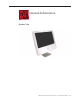
General Information Product View iMac (Early 2006 20-inch) Take Apart — General Information 10
How to identify your iMac On the bottom of your iMac stand, you’ll find a label with the serial number printed on it: This label also provides other information, including the computer configuration and an “EMC” number (EMC No.). The EMC number is unique for different iMac models; just make note of the EMC number on the bottom of your computer and refer to the step #1 below to identify your model. 1. The EMC number for the Intel Core Duo model is 2105 for the 20-inch and 2104 for the 17inch. 2.
What’s New March 2006 • • • A Screw Chart was added. Access tool modification instructions were added. Refer to Opening the Computer in this chapter. Troubleshooting symptom added: No audio from internal speakers (may hear putt-putt). February 2006: Memory • The photographs have been updated in the memory chapter What’s Different on this iMac? Logic board • • • Intel Core Processor 1.83 and 2.
• Updated procedures for formatting hard drives (See Drive Formatting for Intel-based Macs.
Tools Required The following tools are required to service the computer. Note that a special access card (part 9227172) is required to open the front bezel.
Safety Warning: When the iMac (Early 2006) is under power, be aware that the power supply contains high voltages that pose a potential hazard to your personal safety. Never work on or near the power supply with the unit powered on, and as a further precaution always make sure the unit is unplugged when working on it with the front bezel removed. WARNING: HIGH VOLTAGE Text or photographs marked by this symbol indicate that a potential hazard to your personal safety exists from a high voltage source.
Opening the Computer Apple authorized, desktop certified technicians only should ever remove the front bezel on the iMac (Early 2006). When the front bezel is removed, be sure to always ground yourself and follow ESD-safe repair practices Removing the front bezel requires using a special access card (part 922-7172) to release latches located inside the upper corners of the front bezel. Slightly bending the upper quarter of the access tool card will help engage the latch more securely.
2. Cut the EMI gasket to the edge of the access card. 3. Using packing tape, or something equivalent, fold the tape over the EMI gasket to attach the gasket to the card.
4. Bend the card at a slight angle at the top to make sure the card makes contact with each latch. 5. Refer to Removing the Front Bezel for the complete procedure.
EMI Shielding The iMac enclosure is wrapped in EMI shielding that is easily torn and damaged. To maintain a properly shielded unit, you must repair all accidental tears and cracks to the shielding by covering them with EMI tape. Order ������������������������������������������������������������ EMI tape, part number 922-4786 (a long, thin strip) or 9225026 (short, wide strips). Pay particular attention to the EMI shielding inside the rear housing, shown below.
Lower EMI Shield EMI tape covers the top and sides of the display panel, and the lower EMI shield covers the logic board along the bottom of the unit. The EMI tape and lower EMI shield are easily damaged when removed, and removal is necessary in order to access most components within the unit. Should the EMI tape that seals the display, or the EMI shield covering the bottom of the enclosure (see photo below) accidentally tear, use the EMI tape (922-4786 or 922-5026) to repair and completely seal the unit.
When properly repaired, all edges shown below will be wrapped by EMI tape, and the tape securely adhered to all edges. Use a “black stick” to flatten the EMI tape tightly and rub out air pockets and wrinkles.
Access Door Tools • • • Phillips #2 screwdriver ESD-safe workstation and mat Soft , clean towel or cloth Preliminary Steps Before you begin, lay the computer down so the panel is face down and the bottom is facing you.
Removing the Access Door 1. Raise the stand and use a Phillips #2 screwdriver, to loosen the two captive access door screws. Warning: The ambient light sensor is located to the left. Don’t mistake the ambient light sensor for a screw. Sticking a screw driver or other sharp object in the ambient light sensor could damage the computer. 2. Remove the access door. Replacing the Access Door 1. Position the access door on the rear housing over the memory compartment. 2. Lift the stand out of the way. 3.
Memory Tools • • Phillips #2 screwdriver ESD mat, soft , clean towel or cloth Preliminary Steps Before you begin, lay the computer down so the panel is face down with the bottom is facing you; and remove the access door.
Removing the Memory 1. After removing the access door, touch the metal frame around the memory compartment to discharge any static electricity from your body. Important: Always discharge static before you touch any parts such as the memory board. To avoid generating static electricity, do not walk around the room until you have finished replacing the memory. 2. Pull the two levers in the memory compartment toward you. If a memory module is installed in the slot, pulling the levers will dislodge it.
Replacing the Memory 1. Make sure the DIMM levers are all the way open. 2. With the computer face down, orient the DIMM with the notch on the left. 3. With your fingers, press the DIMM fully into the slot until you hear a click. After inserting the memory, fold the DIMM levers closed. There will be a slight resistance and you will hear a click when they fold into the closed position. 4. Replace the access door on the memory compartment. 5.
iMac (Early 2006 20-inch) Take Apart — Memory 27
Front Bezel Tools This procedure requires the following tools: • Torx T8 screwdriver • Access card tool 922-7172 Preliminary Steps Before you begin, remove the access door.
Removing the Front Bezel 1. Position unit on rear cover with the stand facing you. 2. Tilt up the front bezel and remove four screws along the bottom. Warning: The ambient light sensor is located in the second hole from the right. Don’t mistake the ambient light sensor for a screw. Sticking a screwdriver or other sharp object in the ambient light sensor could damage the computer. 3. Locate the access card. Bending the upper quarter of the access tool card will help engage the latch.
4. This picture shows how the access tool works. Pushing the tool up the vent on the rear cover releases the latches on the inside of the front bezel. Refer to the next step for the procedure. 5. Start on the left side (looking from the back of the unit). As you insert the card to disengage the latch, squeeze the top of the bezel, that will help take pressure off of the latch and enable it to open easier. As the bezel releases, pull the bezel away from the rear housing.
6. Repeat step 5 to release the locking latch in the right corner. Again, pull the bezel away as the card releases the latch. 7. If the bezel won’t release, pull the bottom of the bezel out a bit and insert the access card again.
8. Repeat step 7 for the left side. 9. Once the access card has been removed, it is safe to open the bezel. Position the unit on an ESD mat, with the bottom facing toward you. Lift up the top of the bezel and pull it up and slightly toward you. Caution: Make sure the memory eject levers are not protruding from the access door when you lift the bezel up.
10. Swing the bezel up so you can disconnect two cables on the camera board at the top of the bezel. 11. Remove the any kapton tape and disconnect the camera and microphone cables from the camera board. 12. Lift the front bezel off the computer. If replacing a damaged front bezel, also remove the camera board. Note the microphone is part of the front bezel assembly.
Replacing the Front Bezel 1. Make sure the black EMI shielding along the top of the LCD panel is not in the way of the locking mechanisms when you lower the front bezel onto the computer. Use a black stick to press (re-stick) the EMI shielding along the top of the panel. 2. Connect the camera and microphone cables (on the camera board) to the cables sticking out of the top of the computer.
3. Tuck the cables neatly into the channel on the rear housing. 4. Press the memory ejector levers into the closed position. 5. Continue to lower the font bezel down and press the top corners of the front bezel to connect the latches. Note: Check that the latches are connected by lifting the front bezel at each corner. 6. Replace the four bezel mounting screws along the bottom of the computer. 7. Replace the access door; tighten the two captive screws.
Camera Board Tools • • Torx T6 screwdriver ESD mat, soft , clean towel or cloth Preliminary Steps Before you begin, remove the access door and front bezel.
Removing the Camera Board 1. The camera board and cables are visible as you lift the front bezel off the computer. 2. Disconnect the camera and microphone cables.
3. Remove the two T6 screws on the camera board. 4. Peel back the clear mylar material to free the microphone cable from the camera board.
5. Remove the camera board from the front bezel.
Replacing the Camera Board 1. Replace the camera board on the front bezel. Carefully align and insert the camera lens until it is snug in the bezel aperture 2. Replace the two screws on the camera board. Route the microphone cable under the clear mylar. 3. Connect the camera and microphone cables.
4. Tuck the camera board cables neatly into the channel on the rear housing. 5. Position the memory ejector levers into the closed position. 6. Continue to lower the font bezel down over the pull rings (in the memory compartment) and then lower the top corners of the front bezel so they connect with the magnetic latches. Note: check that the latches are connected by lifting the front bezel at each corner. 7. Replace the bezel screws along the bottom of the computer. 8.
Lower EMI Shield Tools The only tool required for this procedure is a black stick (or other nonconductive nylon or plastic flat-blade tool).
Removing the Lower EMI Shield 1. Carefully peel the lower EMI shield off the bottom edge of the rear housing. Use a black stick to help peel back the shield. 2. Gently lift the EMI shield to rest of the way to expose the other modules.
Replacing the Lower EMI Shield 1. Position the lower EMI shield over the bottom of the unit so that the holes (for the IR board and the LED) in the shield are properly aligned. 2. Press the sticky, edge of the EMI shield onto the bottom side of the display panel. The crease in the EMI shield should align with the edge of the panel. 3. Fold down the EMI shield and press it firmly over the bottom edge of the rear housing.
IR Board Tools The only tool required for this procedure is a Torx T6 screwdriver.
Removing the IR Board 1. Disconnect the IR cable and the two T6 screws on the IR board. Lift the IR board from its mounting bracket. 2. Using a Torx T6 screwdriver, remove the two IR board mounting screws. Remove the IR board mounting bracket from the logic board.
3. Note: If you are replacing the IR cable, you must remove the optical drive and disconnect the cable from the logic board.
Replacing the IR Board 1. If removed, route the IR cable as shown below and make sure the cable is connected to the logic board near the optical drive and to the IR board near the memory. 2. Install the IR board mounting bracket, IR board, and screws.
3. Replace the lower EMI shield. 4. Position the memory eject levers into the closed position. 5. Replace the front bezel. 6. Replace the access door.
LCD Display Panel Tools • • • Torx T6 screwdriver.
Removing the Display Panel 1. Peel the bottom of the EMI shield off the frame. 2. Peel the EMI shield up all the way.
3. Using the access tool, a black stick, or your fingers, peel the black EMI tape off the right and left sides of the panel. 4. Using the access tool or black stick, peel back the black EMI tape stuck along the entire length of the top panel.
5. Using a Torx T6 screwdriver, remove the two LVDS connector screws. Pull the black tab on the connector to disconnect the LVDS cable from the logic board. 6. Using a Torx T10 screwdriver, remove the four panel mounting screws.
7. Lift the panel up just enough to see the inverter cables on the left side (Note: this shows the iMac G5 computer, but the procedure is the same). 8. Disconnect the two panel-to-inverter cables on the bottom left side of the display. Replacement Note: The cable connectors are marked with dots to indicate “right-side-up”.
9. Raise the panel up the rest of the way to locate the two inverter cables on the top left side of the display. Replacement Note: The cable connectors are marked with dots to indicate “right-side up”. 10. Lift the panel off the computer. Note: If replacing the display panel, remove the lower EMI shield (if still attached), the display panel mounting brackets, and the LVDS cable from the back of the display panel before returning the module to Apple.
Replacing the Display Panel 1. Replace the LVDS cable on the rear of the display panel. 2. If removed, replace the metal panel mounting brackets to each side of the display. 3. Connect the four inverter-to-display cable connectors. Remember the connectors are keyed; dot-side-up. 4. Replace the display panel with four mounting screws. 5. Connect the LVDS cable connector to the logic board and secure it with two screws. 6.
iMac (Early 2006 20-inch) Take Apart — Display Panel 57
Speakers Tools • Torx T10 screwdriver Preliminary Steps Before you begin, remove the following: • Access door • Front bezel • Lower EMI shield • Display Panel Part Location iMac (Early 2006 20-inch) Take Apart — Speakers 58
Removing the Speakers 1. Using a T10 torx screwdriver, remove the screws from the left and right speakers. Replacement Note: The longer of the two speaker mounting screws is used to secure the left speaker; the shorter screw secures the right speaker. 2. Note the speaker cable routing before removing the speakers. The speaker wire runs around the AirPort Extreme card and above the heatsink.
3. Lift the speakers up and out of the computer. See the next photo for disconnecting the speaker. 4. Under the right speaker, disconnect the speaker cable from the logic board.
Replacing the Speakers 1. Connect the speaker cable to the logic board. 2. Install the speakers and route the speaker wire above the heatsink and around the AirPort Extreme card. 3. Secure the right speaker with the smaller of the two mounting screws. 4. Secure the left speaker with the longer of the two mounting screws. 5. Replace the display panel. 6. Replace the lower EMI shield. 7. Replace the front bezel. 8. Replace the access door.
iMac (Early 2006 20-inch) Take Apart — Speakers 62
iMac (Early 2006 20-inch) Take Apart — Speakers 63
AirPort Extreme Card Tools • Torx T6 screwdriver Preliminary Steps Before you begin, remove the following: • Access door • Front bezel • Lower EMI shield Part Location iMac (Early 2006 20-inch) Take Apart — AirPort Extreme Card 64
Removing the AirPort Extreme Card 1. Using a T6 torx screwdriver, remove the two screws and disconnect the gray antenna from the AirPort Extreme card. 2. The board pops up when the screws are removed. Pull the AirPort Extreme card out of the slot in the direction of the arrow.
Replacing the AirPort Extreme Card 1. Align the AirPort Extreme card with the slot on the logic board. Insert the board into the slot. 2. Replace the two AirPort Extreme card screws. 3. Connect the antenna cable to the lower connector on the AirPort Extreme card. 4. Replace the lower EMI shield. 5. Replace the front bezel. 6. Replace the access door.
Bluetooth Card Tools • Torx T6 screwdriver Preliminary Steps Before you begin, remove the following: • Access door • Front bezel • Lower EMI shield • Speakers Part Location iMac (Early 2006 20-inch) Take Apart — Bluetooth Card 67
Removing the Bluetooth Card 1. Using a T6 torx screwdriver, remove the two T6 screws on the Bluetooth card and disconnect the antenna from the card. 2. Lift the card off the logic board.
Replacing the Bluetooth Card 1. Press the Bluetooth card onto the logic board connector. Note: Make sure the card and antenna are securely connected before installing the speakers. 2. Connect the Bluetooth antenna to the Bluetooth card. 3. Replace the two T6 Bluetooth card screws. 4. Replace the speakers and speaker screws. 5. Replace the lower EMI shield. 6. Replace the front bezel. 7. Replace the access door.
Optical Drive Tools • • • Torx T10 screwdriver Torx T6 screwdriver Flat-blade screwdriver Preliminary Steps Before you begin, remove the following: • Access door • Front bezel • Lower EMI shield • Display Panel Part Location iMac (Early 2006 20-inch) Take Apart — Optical Drive 70
Removing the Optical Drive 1. Looking at the circles below, starting with the top circle, do the following: Peel back the silver EMI tape going from the chassis frame to the optical drive, remove the two T6 screws on the optical drive flex cable, disconnect the flexible cable and the optical drive sensor cable from the logic board. Caution: Never press down on or grasp the body of the optical drive. Pressing or squeezing the body of the optical drive could damage the mechanism.
2. Locate the black release levers on the mounting bracket. Using a flat-blade screwdriver as shown, press straight down at the base of the release lever, while pushing the release lever toward the center of the drive. Pressing down disengages the lever from the chassis. Repeat the process to unhook the other release lever. Refer to step 4 for another visual aide. 3. Repeat the release process on the second lever.
4. This photo shows the optical drive out of the computer so you can visualize how the clips move. Pressing down (#1) releases the clips (#2) outward from the metal chassis. Caution: Never press down on or grasp the body of the optical drive when removing or installing it. Pressing or squeezing the body of the optical drive could damage the mechanism. 5. If replacing the optical drive, use a T6 torx screwdriver to remove two flex cable screws attaching to the optical drive.
6. If replacing the optical drive, disconnect the sensor cable from the optical sensor located on the underside of the optical drive. Transfer the sensor cable to the replacement drive. 7.
Replacing the Optical Drive 1. Install the flex cable to the optical drive with two T6 screws. 2. Insert the optical drive bezel into the rear housing, lining up the bezel with the slot opening (#1) . Be sure to align the two guide holes in the front bezel with guide posts at each end of the drive access hole. Push down on the mounting brackets (#2) to lock the optical drive securely into place on the chassis. Caution: Never press down on or grasp the body of the optical drive when installing it.
3. Connect the optical sensor cable to the logic board, attach the flex cable and secure it with the T6 screws, and reattach the silver EMI tape. 4. Replace the display panel. 5. Replace the lower EMI shield. 6. Replace the front bezel. 7. Replace the access door.
Hard Drive Tools • Torx T10 screwdriver Preliminary Steps Before you begin, remove the following: • Access door • Front bezel • Lower EMI shield • Display Panel Part Location iMac (Early 2006 20-inch) Take Apart — Hard Drive 77
Removing the Hard Drive 1. Remove the two T10 screws attaching the hard drive to the DC/DC inverter board 2. Disconnect the hard drive sensor cable from the connector on the logic board. Note the location of the sensor on the side of the hard drive and the routing of the cable.
3. The hard drive sensor is different from the optical drive sensor. The hard drive sensor can be identified by resistor R1700. Replacement Note: Make sure to transfer the sensor to the replacement hard drive. Use the double-stick tape enclosed with the replacement hard drive to attach the sensor. 4. Holding the drive by the metal bracket, pull the hard drive toward the inverter and then up to release the hard drive mounting pins from the grommets on the chassis.
5. Disconnect the hard drive power and data cables. 6. If you are replacing the hard drive, remove the temperature sensor, mounting bracket, and mounting pins (circled) before returning the drive to Apple. Transfer these parts to the replacement drive.
Replacing the Hard Drive 1. Attach the hard drive sensor and sensor cable to the side of the hard drive. 2. Attach the mounting bracket and pins if they were removed. Connect the hard drive data and power cables.
3. Route the hard drive sensor cable under the metal chassis. Connect the sensor cable to the logic board. 4. Insert the hard drive pins into the grommets. Lower the drive into the rear housing.
5. Secure the two T10 screws on the hard drive mounting bracket to the DC/DC/inverter board. 6. Replace the display panel. 7. Replace the lower EMI shield. 8. Replace the front bezel. 9. Replace the access door.
Power Supply, AC/DC Tools • Torx T10 screwdriver Preliminary Steps Before you begin, remove the following: • Access door • Front bezel • Lower EMI shield • Display panel • Hard drive • Logic board Part Location iMac (Early 2006 20-inch) Take Apart —Power Supply, AC/DC 84
Removing the AC/DC Power Supply WARNING: The AC/DC power supply PCB remains powered up whenever the system is plugged in, whether or not the system has been turned on. Use extreme caution when troubleshooting the system with the front bezel removed. • Don’t work alone. In the event of an electrical shock it is important to have another individual present who can provide assistance. • Keep one hand in your pocket when working on any iMac (Early 2006) system that is plugged in.
2. Lift the power supply up and locate the cable tucked under the inverter. Disconnect the cable. 3. Locate the cable that connects the AC-DC power supply to the AC line filter. The cable is tucked under the metal chassis. With your fingers or a black stick, pry the cable free from the chassis and disconnect it. Lift the power supply out of the chassis.
Replacing the AC/DC Power Supply WARNING: The AC/DC power supply PCB remains powered up whenever the system is plugged in, whether or not the system has been turned on. Use extreme caution when troubleshooting the system with the front bezel removed. • Don’t work alone. In the event of an electrical shock it is important to have another individual present who can provide assistance. • Keep one hand in your pocket when working on any iMac (Early 2006) system that is plugged in.
2. Reconnect the power supply to AC line filter cable. Tuck the cable under the metal chassis. 3. Connect the AC-DC power supply cable to the inverter. Tuck the cable under the inverter board.
4. Replace the power supply screws. Install the machine screw (bottom right corner) first when installing the power supply. 5. Replace the hard drive. 6. Replace the logic board. 7. Replace the display panel. 8. Replace the lower EMI shield. 9. Replace the front bezel. 10. Replace the access door. 11. Replace the display panel. 12. Replace the lower EMI shield. 13. Replace the front bezel. 14. Replace the access door.
Logic Board Tools • Torx T10 screwdriver Preliminary Steps Before you begin, remove the following: • Access door • Front bezel • Lower EMI shield • Display Panel • IR Board • Speakers Part Location iMac (Early 2006 20-inch) Take Apart —Logic Board 90
Removing the Logic Board 1. Disconnect the AirPort and Bluetooth antennas. 2. Disconnect the optical cable, flex cable, and peel back the silver EMI tape from the logic board frame. 3. Disconnect ten cables from the connectors on the logic board.
4. Using a T10 torx screwdriver, remove the seven screws on the board. Replacement Note: Always install the machine screws before installing the self-tapping screws 5. At the top of the heatsink, remove the two screws attaching the logic board support brackets (clips) to the chassis. Note: The support brackets (clips) must be removed and transferred to the new logic board, if replacing the logic board.
6. Holding the board on each side, lift it up and toward the top of the computer. Note: Remove the memory module from the slot before returning the board to Apple . Important: When handling the logic board, never handle the board by the heatsink or metal rails.
Replacing the Logic Board 1. Position all the logic board cables out of the way so the logic board can be placed into the rear housing. 2. As you lower the board into the rear housing, make sure the memory levers are lowered through the access door opening and the logic board screw holes line up with the board.. 3. At the top of the heatsink, replace the two screws attaching the logic board support bracket to the chassis.
4. Make sure the hard drive sensor and the sensor cable are attached to the side of the hard drive. Route the sensor cable under the chassis and connect it to the logic board. 5. Replace the optical drive sensor cable, flex cable and screws, and the silver EMI tape.
6. Using a T10 torx screwdriver, replace the seven screws on the board. Always install the machine screws before installing the self-tapping screws. 7. Connect the cables to the connectors on the logic board.
8. Connect the AirPort and Bluetooth antennas. 9. Replace the speakers. 10. Replace the IR board. 11. Replace the display panel. 12. Replace the lower EMI shield. 13. Replace the front bezel. 14. Replace the memory access door.
iMac (Early 2006 20-inch) Take Apart —Logic Board 98
iMac (Early 2006 20-inch) Take Apart —Logic Board 99
iMac (Early 2006 20-inch) Take Apart —Logic Board 100
AC Line Filter Tools • Torx T10 screwdriver Preliminary Steps Before you begin, remove the following: • Access door • Front bezel • Lower EMI shield • IR Board • Display Panel • Speakers • Logic Board • Hard Drive Part Location iMac (Early 2006 20-inch) Take Apart —AC Line Filter 101
Removing the AC Line Filter 1. Using a torx T10 screwdriver, remove the three self-tapping screws from the power inlet and the machine screw from the ground cable . Remove the EMI tape on the filter. 2. Disconnect the AC filter cable from the power supply. Notice the routing of the AC filter cable under the chassis. 3. Lift the AC filter out of the rear housing.
Replacing the AC Line Filter 1. Install the AC power filter on the rear housing screw mounts with three self tapping screws. 2. Install the power inlet ground cable to the chassis with a machine screw. 3. Route the power inlet cable beneath the chassis as shown in the photo above, and connect it to the power supply. 4. Using the EMI tape, securely tape the top and bottom edges of the AC power inlet to the rear housing. 5. Replace the AC/DC power supply. 6. Replace the hard drive. 7.
iMac (Early 2006 20-inch) Take Apart —AC Line Filter 104
Fan, Hard Drive Tools • No tools are required to remove the hard drive fan.
Removing the Hard Drive Fan Once the logic board and speakers have been removed, the fan will already be disconnected. Lift the fan straight up and out of the rear housing.
Replacing the Hard Drive Fan 1. Lower the fan onto the white posts in the rear housing. Push it down snug onto the posts. 2. Replace the logic board. 3. Replace the speakers. 4. Replace the display panel. 5. Replace the IR Board. 6. Attach the antennas. 7. Replace the lower EMI shield. 8. Replace the front bezel. 9. Replace the memory access door.
iMac (Early 2006 20-inch) Take Apart —Fan, Hard Drive 108
Fan, Optical Drive Tools • No tools are required to remove the optical drive fan.
Removing the Optical Drive Fan Once the logic board and speakers have been removed, the fan will be disconnected. Lift the fan straight up and out of the rear housing.
Replacing the Optical Drive Fan 1. Lower the fan onto the white posts in the rear housing, above the port openings. Route the fan cable around the left side of the fan, through the foam gaskets. Push it down snug onto the posts. 2. Replace the logic board. 3. Replace the speakers. 4. Replace the display panel. 5. Replace the IR Board. 6. Replace the antennas. 7. Replace the lower EMI shield. 8. Replace the front bezel. 9. Replace the memory access door.
Fan, CPU Tools • No tools are required to remove the CPU fan.
Removing the CPU Fan Once the logic board and speakers have been removed, the fan will be disconnected. Lift the fan straight up and out of the rear housing.
Replacing the CPU Fan 1. Lower the fan onto the white standoffs in the rear housing. Push it down snug onto the posts. 2. Replace the logic board. 3. Replace the speakers. 4. Replace the display panel. 5. Replace the IR Board. 6. Replace the antennas. 7. Replace the lower EMI shield. 8. Replace the front bezel. 9. Replace the memory access door.
Power Supply, DC/DC, Inverter Tools • Torx T10 screwdriver Preliminary Steps Before you begin, remove the following: • Access door • Front bezel • Lower EMI shield • IR Board • Display Panel • Speakers • Logic Board • Hard Drive • Power Supply, AC/DC • Hard drive fan Part Location iMac (Early 2006 20-inch) Take Apart —Power Supply, DC/DC, Inverter 115
Removing the DC/DC Power Supply/Inverter 1. Using a torx T10 screwdriver, remove the two power supply, DC-DC inverter screws connecting the board to the rear housing. Disconnect the two cables; one going to the ACDC power supply and the other connecting to the hard drive. 2. Remove just the circled chassis screws, one of which is the AC filter ground screw. Carefully lift the chassis frame just enough to pull the inverter cable from under the metal chassis.
Replacing the DC/DC Power Supply/Inverter 1. Route the inverter cable under the metal chassis frame. Check the routing of the cable so it doesn’t get pinched under the chassis. 2. Install the screws on the chassis frame and the AC filter ground screw. 3. Replace the CPU fan. 4. Connect the cables to the AC/DC power supply and to the hard drive. Replace the two screws connecting the DC/DC power supply/inverter to the rear housing. 5. Replace the AC/DC power supply. 6. Replace the hard drive. 7.
Ambient Light Sensor Board Tools • A black stick or equivalent tool Preliminary Steps Before you begin, remove the following: • Access door • Front bezel • Lower EMI shield • IR Board • Display Panel • Speakers • Logic Board Part Location iMac (Early 2006 20-inch) Take Apart —Ambient Light Sensor Board —118
Removing the Ambient Light Sensor Board 1. Remove the rubber bumper from between the chassis and the sensor board. Note: This shows the procedure on the iMac G5 (iSight) model; the removal procedure is the same. 2. With the rubber bumper gone, use a black stick, pry the ambient light sensor off the inside of the rear housing. The sensor is stuck to the rear housing with double-stick tape. Note: never poke the ambient light or you could damage the sensor board.
Replace the Ambient Light Sensor Board 1. Press the sticky side of the ambient light sensor board to the bottom inside edge of the rear housing. 2. Install the rubber bumper between the back of the sensor board and the chassis. 3. Replace the logic board. 4. Replace the speakers. 5. Replace the display panel. 6. Replace the IR Board. 7. Replace the lower EMI shield. 8. Replace the front bezel. 9. Replace the memory access door.
Cable, Camera and IR Tools No tools are required to remove the camera cable.
Removing the Camera and IR Cable 1. Remove the two-headed end of the cable from the access hole in the upper EMI shield. 2. Remove the tape (under the optical drive) that secures the cable to the rear housing and disconnect the cable from the logic board. Remove the camera cable.
Replacing the Camera and IR Cable 1. Insert the two-headed end of the camera cable through the access hole in the upper EMI shield. 2. Route the camera cable as shown below. Tape the camera cable to the rear housing. 3. Replace the optical drive, flex drive cable and screws, and optical drive sensor cable. 4. Replace the logic board. 5. Replace the speakers. 6. Replace the display panel. 7. Replace the IR Board. 8. Replace the lower EMI shield. 9. Replace the front bezel. 10.
Bluetooth Antenna Tools • Black stick (or other nonconductive nylon or plastic flat-blade tool) Preliminary Steps Before you begin, remove the following: • Access door • Front bezel • Lower EMI shield • Display Panel • Speakers • Display Panel • Optical Drive • Logic Board • Optical Drive Fan Part Location iMac (Early 2006 20-inch) Take Apart —Bluetooth Antenna 124
Removing the Bluetooth Antenna 1. Carefully peel back the EMI shield from the top right inside corner of the rear housing as shown below. Using a flat-blade screwdriver, pry the antenna board off the rear housing. Remove the piece of EMI tape securing the antenna to the chassis. 2. Pull the remaining antenna cable through the opening in the EMI shielding at the top of the EMI shield. Replacement note: the antenna cable runs under the foam gasket (as shown) .
Replacing the Bluetooth Antenna 1. Press the sticky side of the antenna board to the housing until securely fastened. 2. Route the antenna cable on top of the EMI shield along the right side of the rear housing and under the foam gasket. 3. Secure the antenna cable at the top with EMI tape. 4. Replace the optical drive. 5. Replace the fans. 6. Replace the logic board. 7. Connect the Bluetooth antenna to the Bluetooth board. 8. Connect the IR cable to the IR board. 9.
iMac (Early 2006 20-inch) Take Apart —Bluetooth Antenna 127
AirPort Antenna Tools • Black stick (or other nonconductive nylon or plastic flat-blade tool) Preliminary Steps Before you begin, remove the following: • Access door • Front bezel • Lower EMI shield • Speakers • Display Panel • Optical Drive • Logic Board • Hard Drive Fan Part Location iMac (Early 2006 20-inch) Take Apart —AirPort Antenna 128
Removing the AirPort Antenna 1. Carefully peel back the EMI tape (off the chassis) and the EMI backing from the top left inside corner of the rear housing as shown below. Peel back just enough EMI backing to access the antenna board. With a black stick pry the antenna off the rear housing. 2. Remove two pieces of tape that secure the antenna cable to the rear housing. Pull the antenna cable through the access hole at the top of the EMI shield, near the antenna board.
Replacing the AirPort Antenna 1. Route the antenna cable through the hole at the top of the EMI shield. 2. Route the antenna cable down the left side of the EMI shield and above the white plastic standoff (as shown in the middle circle). Secure the extra length of antenna cable to the housing with two pieces of tape .
3. Replace the CPU fan. 4. Replace the logic board. 5. Replace the DC-DC board. 6. Replace the DC power supply. 7. Replace the speakers. 8. Replace the IR Board. 9. Replace the AirPort Extreme board. 10. Replace the Bluetooth board. 11. Replace the display panel. 12. Replace the lower EMI shield. 13. Replace the front bezel. 14. Replace the memory access door.
Clutch Mechanism Tools • Torx T10 screwdriver Preliminary Steps Before you begin, remove the following: • Access door • Front bezel • Lower EMI shield • Speakers • IR Board • Display Panel • Logic Board • CPU Fan Part Location iMac (Early 2006 20-inch) Take Apart —Clutch 132
Removing the Clutch 1. Remove the EMI tape attached along the top and bottom sides of the clutch mechanism cover. After removing the tape, pull the cover straight off the clutch. 2. Peel back the EMI tape on top of the mechanism. Using a torx T10 screwdriver, remove the four clutch mounting screws.
3. Stand up the unit, to access the clutch-to-stand mounting screws. 4. Using a T10 torx screwdriver, remove the seven clutch-to-stand screws. Separate the mechanism and the stand from the rear housing.
Replacing the Clutch 1. Make sure the stand is erect and the end of the stand is inserted through the mounting hole in the rear housing. 2. Position the clutch on the stand, with the clutch springs at bottom. Install the seven long, clutch-to-stand mounting screws. 3. Adjust the clutch so that its chassis mounting holes align, and install the four screws that secure the clutch to the chassis. 4. Replace the silky EMI tape on top of the mechanism, press it into place. 5.
Chassis Tools • Torx T10 screwdriver Preliminary Steps Before you begin, remove the following: • Access door • Front bezel • Lower EMI shield • Speakers • AirPort Extreme • Bluetooth card • IR board • Display panel • Optical Drive • Logic board • CPU Fan • AC Line Filter • Hard drive • Power supply, AC/DC • Clutch • Stand iMac (Early 2006 20-inch) Take Apart —Chassis 136
Part Location Removing the Chassis Using a T10 screwdriver, remove 12 self-tapping screws from the chassis, and remove the chassis from the rear housing.
Replace the Chassis 1. Position the chassis on the rear housing as shown and install 12 self-tapping mounting screws. 2. Replace the clutch mechanism. 3. Replace the AC line filter. 4. Replace the AC/DC power supply. 5. Replace the hard drive. 6. Replace the optical drive. 7. Replace the hard drive and optical drive fans (if removed). 8. Replace the CPU fan. 9. Replace the logic board. 10. Replace the speakers. 11. Replace the display panel. 12. Replace the IR Board. 13.
Rear Housing Tools No tools are required to remove the rear housing.
Part Location Removing the Rear Housing Using a T10 torx screwdriver, remove 12 self-tapping screws from the chassis, and remove the chassis from the rear housing. Note: the EMI shield is part of the rear housing.
Replace the Rear Housing 1. Position the chassis on the rear housing as shown and install 12 self-tapping mounting screws. 2. Replace the clutch mechanism. 3. Replace the stand. 4. Replace the AC line filter. 5. Replace the AC/DC power supply. 6. Replace the hard drive. 7. Replace the optical drive. 8. Replace the hard drive and optical drive fans (if removed). 9. Replace the CPU fan. 10. Replace the logic board. 11. Replace the speakers. 12. Replace the display panel. 13.
Stand Tools • Torx T10 screwdriver Preliminary Steps Before you begin, remove the following: • Access door • Front bezel • Lower EMI shield • Speakers • IR Board • Display Panel • Logic Board • CPU Fan • Clutch Part Location iMac (Early 2006 20-inch) Take Apart —Stand 142
Removing the Stand 1. Stand up the unit, to access the clutch-to-stand mounting screws. 2. Using a T10 torx screwdriver, remove the seven clutch-to-stand screws. Separate the mechanism and the stand from the rear housing.
Replacing the Stand 1. Make sure the stand is erect and the end of the stand is inserted through the mounting hole in the rear housing. 2. Position the clutch on the stand, with the clutch springs at bottom. Install the seven long, clutch-to-stand mounting screws. 3. Adjust the clutch so that its chassis mounting holes align, and install the four screws that secure the clutch to the chassis. 4. Replace the silky EMI tape on top of the mechanism, press it into place. 5.
iMac (Early 2006 20-inch) Take Apart —Stand 145
Service Source Troubleshooting iMac (Early 2006 20-inch) © 2006 Apple Computer, Inc. All rights reserved.
General Information Serial Number Location iMac (Early 2006) serial numbers are located on the bottom of the computer stand. Power On Self Test (POST) Intel-based Macs such as the iMac (Early 2006) rely on a combination of tones and blinking LEDs to display Power On Self Test (POST) error codes. If the computer detects out-of-specification memory or no RAM installed, the screen will be black and the power LED on the front of the computer will blink once a second to indicate bad or no RAM.
DDR Memory The iMac (Early 2006) computer has two SDRAM slots in the bottom of the computer. The iMac ships from the factory with at least 512 MB of DDR2 SDRAM installed into the top slot. (The computer may come with more RAM in the top slot or RAM in the bottom slot, depending on how the computer was ordered from Apple.) The maximum amount of RAM you can install in the iMac is 2 GB total (a 1 GB SO-DIMM in each of the two slots).
Symptom Charts How to Use the Symptom Charts The Symptom Charts included in this chapter will help you diagnose specific symptoms related to the product. Because cures are listed on the charts in the order of most likely solution, try the cures in the order presented. Verify whether or not the product continues to exhibit the symptom. If the symptom persists, try the next cure. Note: If a cure instructs you to replace a module, reinstall the original module before you proceed to the next cure.
Power Issues No Power. The iMac (Early 2006) will not turn on. The display remains black and there are no sounds from the fans or drives. 1. Verify the power outlet is good. Plug a different device into the socket to ensure there is power, or plug the iMac into another outlet. Does the iMac power on now? Yes. Resolved. Bad outlet. No: Go on to the next step. 2. Check the power cord. Use a known good power cord. Does the iMac power on now? Yes: Your power cord has failed. Replace the AC power cord.
No: Your logic board is not communicating with LCD panel. Open the unit and re-seat the TMDS cable and test again. If the issue persists, replace the main logic board. Audible buzzing, whining, or ticking noise The iMac (Early 2006) contains several mechanical devices such as motors and fans that may make audible buzzing, ticking, or whining noises when they are operating in a normal manner. The sounds will vary depending on how the system is used. When troubleshooting abnormal noises try the following: 1.
No Video No Video, No Boot Chime, White LED ON (Symptom 1) The iMac (Early 2006) will turn on (indicated by the front LED ON), but there is NO boot chime and No Video on the display. The faint sound of the fans, hard drive, and optical drive may also be heard. 1. Reset the SMC (Formerly SMU). - Turn off the computer by choosing Shut Down from the Apple menu, or by holding the power button until the computer turns off. - Unplug all cables from the computer, including the power cord. - Wait 15 seconds.
- - - should hear the fans go quiet. While the computer is off, with your left hand, hold down the Apple key, the Option key next to it, and the letter “R” key on the keyboard. When you have these keys all pressed down, push the power button with your right hand and then quickly move that hand to hold down the letter “P” on the keyboard. Keep these four keys pressed while the computer starts up. Make sure you hold down the four keys (P - R - Apple - Option) while the computer is starting up.
Yes: Replace the original SDRAM and test again. If the front LED does not go off with the only the original SDRAM installed, replace the SDRAM. If the LED is now reliably going off after a few moments, but yet you still do not have any video, go to step 8. No: If the LED remained on, the main logic board is not communicating with the LCD panel to generate video. Replace the main logic board. 7. With the LED going off, you may have a No Backlight condition or an LCD failure.
1. Open the Energy Saver System Preferences and temporarily set the display to sleep after one minute. Set the computer to sleep after ten minutes. Once the Energy Saver preferences have been set, wait for the display to go to sleep.
2. Wake the display from sleep and observe the display. Does the image on the display shimmer or fill with horizontal or vertical lines when waking from sleep? Yes: Replace the main logic board No: Continue troubleshooting using appropriate symptom charts Note: To ensure optimal image quality the system should be left unplugged for approximately two hours after reproducing this failure.
Display When displaying a single color over the screen area, the LCD panel shows one or more pixels that are not properly lit Active-matrix LCD technology uses rows and columns of addressable locations (pixels) that render text and images on screen. Each pixel location has three separate subpixels (red, green, and blue) that allow the image to be rendered in full color. Each subpixel has a corresponding transistor responsible for turning the subpixel on or off.
Hard Drive Flashing question mark, or an alternating question mark and Mac OS (face or a folder) Note: When troubleshooting hard drive problems it is a good idea, if possible, to back up any important data. Some troubleshooting steps may require erasing the contents of the hard drive. 1. Boot from the system CD that came with the computer, and open Disk Utility. Does the hard drive show in Disk Utility? Yes: Run Repair Disk and Repair Permissions to correct any directory and permissions issues.
System hangs during normal startup process 1. Boot from the system CD that came with the computer and see if the hard drive mounts on the desktop. 2. Using Drive Setup, reinstall the system software drivers for the hard drive. 3. Using Drive Setup, reinitiation the hard drive. 4. Check all cable connections to and from the hard drive. 5. Replace the hard drive data cable. 6. Replace the hard drive. 7. Replace the logic board.
Optical Drive CDs or DVDs don’t show up on the Desktop. 1. Select Preferences from the Finder menu and make sure the option to show CDs, DVDs and iPods is checked: in the General window as shown below.
2. Select System Preferences from the Apple menu and open the CDs & DVDs preferences window. Make sure that audio CDs are set to launch iTunes and movie DVDs set to launch DVD Player when those media are inserted, as shown below. 3. Check that the drive can read discs normally. Insert an audio CD and check whether it shows up on your desktop or launches iTunes. Does the audio CD mount on the desktop or in iTunes? Yes: The drive seems to read CD discs okay. Go on to Step 4.
The computer won’t burn discs. 1. Check whether the drive can read CDs and DVDs normally. Perform the steps above for “CDs or DVDs don’t show up on the Desktop.” 2. Try a test burn by creating a Burn Folder, as follows. • In the Finder, choose “New Burn Folder” from the File menu. • Open the Burn Folder, drag an item inside for testing, and click “Burn” in the upper right corner of the window. • When prompted, insert a blank disc and follow the dialog instructions.
No: Replace the optical drive. Does it burn correctly now? Yes: Problem solved. No: Replace the logic board. Discs won’t insert. 1. Is there a disc already in the drive? Yes: Eject the disc before inserting another. Refer to Knowledge Base article 106752, “Macintosh: How to Eject a Disc When Other Options Do Not Work”. If none of these options will eject the disc, you may have to disassemble the drive to recover the disc.
Optical disc constantly ejects 1. Disconnect all peripheral devices, especially the mouse in cases where the disc is constantly ejecting. Retest. If the issue is resolved, reconnect peripherals one-at-a-time until faulty peripheral is identified. 2. Try cleaning the disc. If the disc is dirty or scratched, it may not mount. Is the issue resolved? Yes: Problem solved. No: Try a different disc. If the issue persists, go on to the next step. 3.
Fan Sound Fans running at full speed after the computer turns on The customer may have entered a diagnostic mode that causes the fans to run at full speed.* Restarting the system will not restore normal fan operation. To solve the problem, the user or technician should do the following: 1. Shut down the system. 2. Disconnect the power cord and wait 15 seconds. 3. Reconnect the power cord and wait 5 seconds. 4. Power on the system.
sound is related to one of the components. Go to step 4. The sound varies: Under normal conditions rotating blowers will make a slight hum that varies in relationship with their rotational speed and the amount of air that they are moving. Let’s see if this is indeed the case. Go to Next Step. 3. Are the fans making a normal humming sound that increases/decreases in relation to processor usage? As the fans increase their speed to cool the system the sound level will increase.
remove the access door, front bezel, and EMI shield. Stand up the computer, plug it in, and start it up by pressing the external power button. As the machine starts up, listen carefully to each of the three fans, and see if you can locate the fan from which the objectionable ticking, whistling, or squealing sound is coming. The CPU fan is the left-most fan, the hard drive fan is in the center, and the optical drive fan is on the right. Can you pinpoint the fan making the sound? Yes: Replace the noisy fan.
AirPort/ Not able to connect wirelessly with AirPort 1. From the Apple menu, choose About this Mac. 2- Click on More Info. System Profiler should open. 3- In System Profiler, in the column on the left, look under Network for a line called “AirPort Card”. Select that line. 4- Does the section to the right say “No Information Found”? Yes: The computer doesn’t realize it has an AirPort card installed. Go to step. 5 No: The iMac recognizes that it has an AirPort card installed. Go to step 6.
IR Remote Remote won’t communicate with system applications such as iTunes or iPhoto, or with the optical drive. Make sure of the following when using the Apple Remote: • You are within 30 feet of the front of the computer. • You have an unobstructed line-of-sight to the front of the computer. • You are pointing the lens end of the Apple Remote directly at the front of the computer. • The computer is powered on and awake.
IR Sensor/Receiver Supported applications do not respond to input from the remote control. 1. Perform the checks above under “IR Remote” to verify that the Apple Remote is functioning correctly, and retest. Do supported applications now respond to input from the IR remote? Yes: Problem resolved. No: Go to the next step. 2. Verify that the IR Sensor can be seen in the Apple System Profiler. Open the Apple System Profiler and click on the “USB” section.
Built-in iSight Camera The built-in camera is not recognized. 1. Boot the iMac (Early 2006) to the desktop and launch iChat AV. Note: You do not need to be connected to a network to use iChat AV to troubleshoot. Verify that the correct versions of Mac OS X and iChat AV are installed. Reinstall or update software as needed. 2. Open the iChat AV preferences and click on the ‘Video’ icon. Verify whether the camera is recognized by the iChat AV software.
iChat AV connection doctor feature to verify that there is sufficient bandwidth to have a video iChat session without a significant degradation of image quality. No: The camera may not be functioning normally. Replace the camera board in the front bezel and retest. Camera recognized but no audio 1. Open the System Preferences window and click on Sound. 2. Verify that the built in iSight camera has been selected as the device for sound input. 3.
Speakers Can’t hear sound from the speakers. 1. Disconnect any external microphones, speakers, or headphones. 2. Access System Preferences and select Sound. In the Sound pane, select Output and make sure the Internal speakers are selected as the device for sound output, the Output volume is adequate, and Mute is not selected. Do you have sound now? Yes: Problem resolved. No: Go to the next step. 3. Reset parameter RAM. Press Command-Option-P-R during startup but before “Welcome to Macintosh” appears.
I hear sound out of only one speaker. 1. Are there any external microphones, speakers or headphones plugged into the iMac? Yes: Disconnect any external microphones, speakers, or headphones. Do you hear audio from both of the built in speakers on your iMac? Yes: Good. It looks like the built-in speakers are working properly. This may be an issue with the microphone, speakers or headphones that were plugged into your iMac. Please work with the manufacturer to troubleshoot this issue. No: Go to step 2.
Mouse My mouse doesn’t work at all. 1. Turn over the mouse and check the if the red LED on the underside of the mouse. Is the LED lit? Yes: The mouse has power. Try using the mouse on another surface. Non-reflective, opaque surfaces without repetitive patterns work best. The surface should be clean, but not shiny. Optical mice won’t work on glass, mirrored surfaces, glossy materials or mouse pads with pictures. No: There is no power to the mouse.
Keyboard Certain keys or none of the keys on the keyboard function. 1. Unplug all devices from your computer, including your mouse and keyboard as well as printer, scanner, external hard drives, and hubs. (Warning: Some devices may require you to perform steps before it is safe to unplug them, e.g, external storage devices.) Be sure to unplug your hub, if you have one. 2. Plug your keyboard into the back of your computer firmly and securely.
6. Close the System Preferences. Try typing a few characters. Did is solve the problem? Yes: Problem solved. No: Replace the keyboard. The USB port on my keyboard doesn’t work. 1. Unplug all devises from your keyboard. 2. Plug your Apple mouse into the left USB port on your keyboard. Does your mouse work when it’s plugged into this port? Yes: Now plug the mouse into the right port. Does it work? Yes: Try a known good keyboard. No: Try a known good mouse to rule out the mouse. Then go to step 3.
USB A USB device doesn’t work 1. Please unplug all of your USB devices from your iMac except your Apple Keyboard and Apple mouse. 2. Now plug your device directly into the back of your iMac. Does it work as expected now? Yes: Your device works when plugged directly into the computer. This indicates a conflict with one of the other USB devices. You can test by gradually adding your devices back and seeing where the issue occurs, then contacting the manufacturer of the device(s)) for assistance.
iMac (Early 2006 20-inch) Troubleshooting — Symptom Charts 179
Service Source Views iMac (Early 2006 20-inch) © 2006 Apple Computer, Inc. All rights reserved.
iMac (Early 2006 20-inch)—Upper Exploded View iMac (Early 2006 20-inch) — Views 181
iMac (Early 2006 20-inch)—Lower Exploded View iMac (Early 2006 20-inch) — Views 182
Screw Chart Screw Chart : iMac (Early 2006 20-inch): page 1 Note: Screws are not to scale.
Screw Chart: iMac (Early 2006 20-inch) page 2 922-7001 head T8, round T10 A/C to chassis 922-7014 T10 LCD bracket to 20-inch LCD Hard drive pins (2) 922-7069 922-7163 T10 922-7066 T10 922-7023 T10 LCD assembly to rear cover 922-6842 T10 DC board to rear cover DC board to rear cover 922-7015 922-7018 T10 T8 Left speaker, 20-inch Right speaker, 20-inch Optical bezel to optical drive 922-7011 922-7019 922-7020 T8 Front bezel to bottom frame T8 Hard drive clip to hard drive T10 B