Service Source iMac (24-inch Early 2008) 20 June 2008 © 2008 Apple Inc. All rights reserved.
Apple Inc. © 2008 Apple Inc. All rights reserved. Under the copyright laws, this document may not be copied, in whole or in part, without the written consent of Apple. Every effort has been made to ensure that the information in this document is accurate. Apple is not responsible for printing or clerical errors. Apple 1 Infinite Loop Cupertino, CA 95014-2084 USA + 1 408 996 1010 www.apple.com Apple, the Apple logo, Mac, and Macintosh are trademarks of Apple Inc., registered in the U.S.
iMac (24-inch Early 2008) Contents Manual Updates 7 Updated 20 June 2008 7 Product Introduced April 29, 2008 7 Take Apart General Information 10 What’s New 10 Product Configurations 11 Opening the Computer 11 Note About Images in This Manual 11 General Tools 12 Required Special Tools 12 View of the iMac with the Front Bezel Removed 14 View of the Modules with the Display Panel Removed View of the Rear Housing and Cables 15 Back View 15 I/O Ports 16 Cleaning and Handling the Glass Panel 17 Do’s and Don’ts
Cleaning Tool Kit 41 Cleaning Tool Resources 41 LENSPEN Screen Cleaning Device Ionizing Air Gun 43 42 Front Bezel 44 Camera Board 50 Battery 53 IR (Infrared) Board 56 AirPort Extreme Board 59 Bluetooth Board 63 LCD Display Panel 66 LCD Temp Sensor Cable 73 Left Speaker 79 Ambient Temp Sensor 83 Ambient Temp Sensor Cable 87 LVDS Display Cable 91 Right Speaker 97 Inverter Cable 100 Optical Drive Fan 104 CPU Fan 107 Power Supply, AC/DC Hard Drive 110 117 Hard Drive Sensor Cable 124 Optical Dri
Hard Drive Fan 154 Audio Board 157 Hard Drive Data Cable 160 Clutch Cover 163 Stand 166 Clutch Mechanism 171 Chassis 175 Camera Cable 180 Microphone Cable 185 Cable, DC, Power Supply/SATA 190 Rear Cover 195 Troubleshooting General Information 199 Serial Number 199 Power On Self Test (POST) 200 Firmware Updates 200 Diagnostic LEDs 202 Apple Hardware Test (AHT) Error Codes 204 Logic Board Sensor and Fan Connector Locations, Top Side Logic Board Sensor Locations, Back Side 207 Cleaning Tools for the LCD
IR Remote 233 IR Sensor/Receiver 234 Built-in iSight Camera 235 Speakers 237 Mouse (also see Wireless Issues topic) 238 Keyboard (also see Wireless Issues topic) 239 Wireless Issues (also see Additional Wireless Topics) 241 Additional Wireless Topics 245 Error Beep(s) 246 USB 247 Views iMac (24-inch Early 2008)—Upper Exploded View 249 iMac (24-inch Early 2008)—Lower Exploded View 250 Screw Chart 251 vi
Manual Updates Updated 20 June 2008 Troubleshooting • Symptom Charts: • Added new troubleshooting symptom: Optical Drive-->Optical drive won’t eject media. Verify that two or three black clips (on the bezel) are positioned on top of the optical drive mechanism. Refer to the topic for images and more information. • Added a new troubleshooting symptom: Error Beeps-->iMac display is black and the system beeps nine times (3 short, 3 long, 3 short), then repeats.
• Symptom Charts: • Updated symptoms throughout for clarity and removed irrelevant links • Added new troubleshooting sections called Wireless Issues and Additional Wireless Topics to help troubleshoot wireless keyboards and mice • Added new symptoms: Some keys not working on the wireless keyboard and Contamination on the inside surface of the glass panel.
Service Source Take Apart iMac (24-inch Early 2008) © 2008 Apple Inc. All rights reserved.
General Information Product View What’s New The iMac (24-inch Early 2008) computer has the same overall look as the previous iMac. The big differences are the upgraded processor (Intel Penryn chip) and the faster RAM speeds. New features: • 2.8 or 3.06 GHz (optional) Intel Core 2 Duo processor • 1066 MHz front side bus • Mac OS X version 10.5.
Product Configurations To confirm the configuration from the Apple menu, choose About This Mac. The Processor listing will show the speed of the processor followed by the processor type. The following table shows the iMac (24-inch Early 2008) model configuration at introduction: Feature iMac (24-inch Early 2008) Intel Core 2 Duo processor 2.8 GHz or 3.
General Tools The following tools are required to service the computer: • ESD-safe workstation and mat • Soft, clean towel or cloth (to protect the display and removed parts from scratches) • Black stick (or other non-conductive nylon or plastic flat-blade tool) • Phillips #2 screwdriver • Torx T6 screwdriver (magnetized) • Torx T8 screwdriver (magnetized) • Torx T10 screwdriver (magnetized) • Flat-blade screwdriver • Isopropyl alcohol • ESD bags Required Special Tools Special tools are required to remove,
Cleaning Tools Starter Kit The following tools are offered in the starter kit (076-1277).
View of the iMac with the Front Bezel Removed View of the Modules with the Display Panel Removed iMac (24-inch Early 2008) iMac (24-inch Early 2008) — 14General Information
View of the Rear Housing and Cables This is a view of the rear housing with the chassis, stand and mechanism removed. Back View The input/output ports are located on the bottom left side on the back of the computer. The power on button is located on the bottom right side on the back of the computer.
I/O Ports The input/output ports from left to right are: • Headphone out/optical digital audio out port • Audio in/optical digital audio in port • USB 2.
Cleaning and Handling the Glass Panel Follow the cleaning procedures in this manual to ensure the glass panel is free of dust and other particles before returning the computer to the customer. Note: To view the movie, make sure the manual is opened in Acrobat. • • • • • The iMac (24-inch Early 2008) model has a glass panel that attaches to the outside of the front bezel. The glass panel is not tempered and will break into sharp pieces if mishandled.
Do’s and Don’ts DO • • • • • • • • Handle glass panel using lint free gloves. Use only a sticky silicone roller to clean the inside surface of the glass and the LCD panel. Use iKlear ONLY on the outside surface of the glass panel or use the LENSPEN. Place the glass panel into a clean protective microfoam bag when it is not installed on an iMac. Store the glass panel in a safe area where it will not be broken or damaged.
Safety WARNING: HIGH VOLTAGE: The highlighted module below is an AC/DC power supply that poses a shock hazard. When the computer is under power, be aware that the power supply contains high voltages that pose a potential hazard to your personal safety. Never work on or near the power supply with the unit powered on; and as a further precaution, always make sure the unit is unplugged when working on it with the front bezel removed.
EMI Shielding The rear cover of the computer is wrapped in EMI shielding that is easily torn and damaged. To maintain a properly shielded unit, you must repair all accidental tears and cracks to the shielding by covering them with EMI tape that can be ordered from Apple service.
Access Door Tools • • • Phillips #2 screwdriver ESD-safe workstation and mat Soft , clean towel or cloth Preliminary Steps Before you begin, place the computer face down on a clean, soft, lint-free cloth so that the bottom is facing you.
Removing the Access Door 1. Disconnect all cables and the power cord from your iMac. 2. Place a soft, clean towel or cloth on your work surface. Hold the side of the iMac and lay it down so that the screen is against the surface and the bottom is facing you. 3. Raise the stand and use a Phillips #2 screwdriver to loosen the captive screw on the memory access door by turning it counterclockwise.
Memory Tools • • ESD mat Soft , clean towel or cloth Preliminary Steps Before you begin, remove the access door. Warning: Always shut down the computer and remove the power cord before installing memory. Do not attempt to install memory in the computer while it is plugged in.
Removing the Memory 1. Shut down the computer, and disconnect all cables including the power cord. 2. Holding the sides of the computer, lay it face down on a soft, clean cloth so the stand is facing you. 3. After removing the access door, touch the metal stand or bezel to discharge any static electricity from your body. Important: Always discharge static before you touch any parts such as the memory board.
Replacing the Memory 1. With the computer face down, orient the notch on the DIMM with the notch in the memory slot. In this case, the notch is on the left. 2. With your fingers, press the DIMM fully into the slot until you hear a click. Repeat for the other DIMM slot. 3. Fold the black tab over each DIMM. 4. Replace the memory access door. 5. Use a Phillips #2 screwdriver to tighten the captive screw on the memory access door. 6.
Glass Panel Tools This procedure requires the following tools, which are offered individually or as part of the cleaning kit, 076-1277.
This iMac model has a glass panel that attaches to the outside of the front bezel. The glass panel is not tempered and will break into sharp pieces if mishandled. A scratched or broken glass panel is not covered under warranty. Removing the glass panel requires special tools such as lint-free gloves, rubber suction cups, microfoam storage bags, and the iKlear cleaning solution. The glass panel must be removed prior to replacing any module other than the SO-DIMM’s.
Isopropyl Alcohol (IPA) Cleaning the Glass In the unfortunate event that gloves are not worn, and fingerprints and oil smudges are visible on the inside of the glass, cleaning should be done using a lint free cloth and IPA. Spray a small amount of IPA onto a CLEAN lint free cloth to avoid introducing any other contaminants. Gently wipe the area and allow the glass to dry. Note: The silicone rollers are only effective in removing dust and other particles.
Metal Alignment Pins on the Glass Panel There are alignment pins at the top of the glass panel near the camera, one pin at the bottom near the IR remote sensor, and a pin on the left and right side of the glass. Important: If the glass is removed from the bezel at an angle, the metal alignment pins may bend, causing scratches on the inside of the glass and possibly requiring replacement of the glass panel.
Removing the Glass Panel 1. Apple strongly recommends wearing clean lint-free gloves whenever handling the glass panel. The gloves protect the glass panel from body oils, dirt, and other contaminants. Put on a pair of clean gloves with the rubberized-side of the gloves on the palm side of your hand. 2. Position the computer on the rear cover, on a soft protective lint-free surface, with the stand facing you 3. Clean off the suction cups, making sure they are free of contaminants.
4. Gently press the suction cups in opposite corners on the glass panel, as shown. Important: Make sure the suction cups are firmly attached to the glass before lifting the glass. 5. Hold onto the suction cups and gently lift the glass panel straight up and off the bezel.
6. Set the glass down on the microfoam bag or clean lint-free surface and remove the suction cups. Squeeze the base of each suction cup to release them from the glass panel. 7. Touching only the edges of the glass, slide the glass panel into the microfoam static-free bag. Set the glass aside in a location where it won’t get damaged. The bag will help minimize contamination of the glass.
Replacing the Glass Panel 1. Put on a pair of clean gloves with the rubberized-side of the gloves on the palm side of your hand. 2. Install the LCD display panel onto the computer if it was removed. 3. Replace the font bezel if it was removed, connect the microphone cable and replace the bezel screws. 4. Locate the sticky silicone roller and the dust removal pad. Remove the protective covering on the silicone roller and peel the protective cover off the dust removal pad.
5. Holding the sticky paper with your free hand, clean the silicone roller on the sticky paper by rolling the roller back and forth once or twice on the sticky paper. If the sticky paper has been used multiple times and looks dirty, use a new piece of sticky paper. Note: Wash the silicone roller in warm soapy water if the roller is no longer tacky. Replace the silicone roller if the tackiness does not return. 6.
7. REMINDER: WEAR CLEAN GLOVES AND ONLY HANDLE THE GLASS BY THE EDGES. 8. Stand the computer upright. Note: Less dust particles will settle on the LCD panel with the computer in the vertical position. 9. Roll the sticky silicone roller over the LCD panel to remove any particles. Note: A larger silicone roller was used for demonstration purposes, however; the 6-inch silicone roller from Apple service will suffice. 10. Remove the glass panel from the microfoam bag.
11. Clean the INSIDE of the glass panel with the clean silicone roller to remove dust or other loose particles. Gently roll the clean silicone roller over the inside of the glass. Note: If fingerprints and oils are on the inside of the glass, clean the inside first with isopropyl alcohol or use the LENSPEN LapTop PRO. 12. Holding the glass by the edges, carefully line up the metal pins on the inside of the glass panel with the holes at the top of the front bezel and the hole at the bottom of the bezel.
13. Clean the outside of the glass panel with a clean microfiber cleaning cloth. If necessary, spray a small amount (two pumps) of iKlear polish on the outside of the glass panel. Wipe the glass until the solution completely disappears and there is no longer any residue or haze. CAUTION: Do not use single wipe iKlear packets or other cleaning solutions to clean the glass. The LENSPEN LapTop PRO is also a very effective tool to use for smudges or fingerprints on the outside of the glass panel. 14.
Installing a Replacement Glass Panel 1. Stand the computer upright. Note: Fewer dust particles will settle on the LCD panel with the computer in the vertical position. 2. Roll the sticky silicone roller over the LCD panel to remove any particles. 3. Remove the new glass panel from the service packaging. Note: The new panels have a removable film protecting the glass on both sides. 4. Place the glass on a clean microfoam bag with the inside of the glass facing up (the side with metal pins.
5. Clean the INSIDE surface of the glass panel with the silicone roller. Gently roll the clean silicone roller over the inside surface of the glass. Note: If fingerprints and oils are on the inside of the glass, clean the inside first with isopropyl alcohol or use the LENSPEN LapTop PRO. 6. Holding the glass by the edges, carefully line up the metal pins on the inside of the glass panel with the holes at the top of the front bezel and the hole at the bottom of the bezel.
7. Peel the protective film from the outside surface of the glass panel. If the glass panel pulls away from the front bezel, gently hold it in place while removing the protective film. 8. Clean the outside of the glass panel with a clean microfiber cleaning cloth and use the LENSPEN LapTop PRO to remover smudges or fingerprints on the outside of the glass panel. 9. If necessary, spray a small amount (two pumps) of iKlear polish on the outside of the glass panel.
Cleaning Tool Kit The following tools are offered in the cleaning kit (076-1277). • Suction cups, Qty. of one (pair) • Sticky silicone roller (6-inch) to clean the glass panel, Qty. of one • Sticky sheets to clean the silicone roller, Qty. of 2 pads • Polishing cloths, clean, anti-static, micro fiber “terry” style cloth, Qty. of one (5 cloths) • Gloves, lint-free, anti-static, Qty. of two (pair) • Microfoam bag to store the glass panel, Qty. of one (5 bags) • ESD bag for LCD display storage, Qty.
LENSPEN Screen Cleaning Device LENSPEN products are simple to use and are effective at removing smudges and fingerprints on the inside/outside of the glass panel. The two LENSPEN products that have been tested on the iMac are shown below, the VidiMax and the LapTop-Pro. Refer to www.lenspen.com for more information.
Ionizing Air Gun The ionizing air gun is an optional tool you may want to consider when cleaning iMac glass panels. The ionizing gun performs electrostatic elimination and dust removal instantly with ion balanced air. Various sources can be found in Google.
Front Bezel Tools This procedure requires the following tools: • Torx T8 screwdriver • Soft, clean towel or cloth Preliminary Steps Before you begin, remove the: • Access door • Glass panel Part Location iMac (24-inch Early 2008) Take Apart — Front Bezel 44
Removing the Front Bezel 1. Place the computer on a soft protective lint-free surface such as a very clean ESD mat to avoid damaging the finish on the stand or rear housing. 2. Position the computer on the rear cover with the stand facing you. 3. Remove the twelve screws around the bezel. Replacement Note: Refer to the photo when replacing the screws.
4. With the upper corners loosened, lift up—but do not remove—the bezel. 5. Notice the connected microphone cable at the top of the bezel. Without straining the cable, hold the bezel up, and disconnect the microphone cable from the cable extension.
6. Continue lifting the front bezel toward you and off the rear housing.
Replacing the Front Bezel 1. Place the computer on a soft protective lint-free surface such as a very clean ESD mat to avoid damaging the finish on the stand or rear housing. 2. Position the computer on the rear cover with the stand facing you. 3. Position the bottom of the front bezel over the bottom edge of the rear cover. 4. Lower the front bezel, connect the microphone cable to the extension cable and tuck the cable into the computer housing.
5. Replace the twelve screws around the bezel. The two longer screws (30mm) attach to the bezel along the bottom of the panel, on the right and left side of the Apple logo. The four medium length screws (19mm) attach above and below the optical drive on the right side, and on either side of the 30mm screws. The six shorter screws (15mm) attach around the top, and left side. 6. Clean and replace the glass panel. Note: This step is very important.
Camera Board Tools This procedure requires the following tools: • Torx T8 screwdriver • Soft, clean towel or cloth Preliminary Steps Before you begin, remove the: • Access door • Glass panel • Front bezel Part Location iMac (24-inch Early 2008) Take Apart — Camera Board 50
Removing the Camera Board 922-8171 1. The camera board bracket and cable are visible after you remove the front bezel off the computer. 2. Remove two T8 screws on the camera bracket. 3. Lift the camera bracket out of the rear housing enough to access the Kapton tape securing the camera cable. 4. Unwrap the Kapton tape covering the camera cable and connector. Disconnect the camera cable from the camera board. Set the camera board and attached bracket aside.
Replacing the Camera Board 1. Connect the camera cable to the camera board. Reapply the kapton tape over the cable and connector. 2. Lower the camera bracket onto the black posts on the rear cover. 3. Replace the two T8 screws. 4. Replace the front bezel. 5. Clean and replace the glass panel. Note: This step is very important. Follow the procedures to ensure the glass is clean and free of particles. 6. Replace the access door.
Battery Tools The only tool required for this procedure is a black stick (or other nonconductive plastic or nylon tool).
Removing the Battery Use a black stick to pry out the battery from the battery socket on the logic board. Replacing the Battery 1. Make sure the battery socket is open and free of dust. 2. Press the battery into the socket. Make sure the side with the engraved markings (+ side) is facing up .
3. Replace the front bezel. 4. Clean and replace the glass panel. Note: This step is very important. Follow the procedures to ensure the glass is clean and free of particles. 5. Replace the access door.
IR (Infrared) Board Tools The only tool required for this procedure is a black stick (or other nonconductive plastic or nylon tool).
Removing the IR Board 1. Remove the two T6 screws from IR board and disconnect the IR cable from either the IR board (circled) or the logic board. Note: It doesn’t matter which board you disconnect the IR cable from when removing the IR board. 2. Lift the IR board from the heatsink.
Replacing the IR Board 1. Connect the IR cable to the IR board. 2. Install the IR board and T6 screws. 3. If removed, connect the IR cable to the logic board. 4. Tuck the IR cable under the black plastic cable guide. 5. Replace the front bezel. 6. Clean and replace the glass panel. Note: This step is very important. Follow the procedures to ensure the glass is clean and free of particles. 7. Replace the access door.
AirPort Extreme Board Tools • Torx T6 screwdriver Preliminary Steps Before you begin, remove the: • Access door • Glass panel • Front bezel Part Location iMac (24-inch Early 2008) Take Apart — AirPort Extreme Board 59
Removing the AirPort Extreme Card 1. Using a T6 torx screwdriver, remove the one 5-mm long screw and disconnect the two antenna cables from the AirPort Extreme card. Note: The antenna cables and connectors are very delicate and should be carefully removed by pulling on the antenna cable connectors, not on the cables. 922-7010 1. 2. Holding the card by the edges, pull the AirPort Extreme card out of the slot.
Replacing the AirPort Extreme Card 1. Align the AirPort Extreme card with the slot on the logic board. Insert the board into the slot. 2. Connect the antenna cables to the connectors on the AirPort Extreme card. Note: The antenna cables might include an “L” or “R” tab near the connector end; however, you can disregard that because the cable position can be swapped without any change in performance. Replace the T6 screw.
3. Replace the front bezel. 4. Clean and replace the glass panel. Note: This step is very important. Follow the procedures to ensure the glass is clean and free of particles. 5. Replace the access door.
Bluetooth Board Tools • Torx T6 screwdriver Preliminary Steps Before you begin, remove the: • Access door • Glass panel • Front bezel Part Location iMac (24-inch Early 2008) Take Apart — Bluetooth Board 63
Removing the Bluetooth Board 922-7010 1. Disconnect the blue Bluetooth antenna from the top left corner of the board. Note: The antenna cable and connector are very delicate and should be carefully removed by pulling on the antenna cable connector, not on the cable. 2. Disconnect the tiny, black cable Bluetooth cable that connects from the Bluetooth board to the logic board. 3. Using a T6 torx screwdriver, remove the T6 screw from the lower left corner of the Bluetooth board.
Replacing the Bluetooth Board 1. Connect the tiny, black Bluetooth cable to the Bluetooth board and to the logic board. 2. Press the Bluetooth board onto the logic board connector. 3. Connect the Bluetooth antenna to the Bluetooth board. 4. Replace the one T6 screw in the lower left corner of the Bluetooth board. 5. Replace the front bezel. 6. Clean and replace the glass panel. Note: This step is very important. Follow the procedures to ensure the glass is clean and free of particles. 7.
LCD Display Panel Tools • • Torx T6 screwdriver Torx T8 Screwdriver Preliminary Steps Before you begin, remove the: • Access door • Glass panel • Front bezel Important: To prevent the buildup of static charges which may attract dust particles to the surface of the display, store the LCD panel in an anti-static bag whenever it has been removed from the system.
Removing the Display Panel 1. Place the computer with the display face up. 2. Remove the two T6 screws from the LVDS connector. Pull the black tab on the cable, or grasp the connector by the edges to disconnect it from the logic board. 3. Disconnect the display sensor cable from the left side of the logic board.
4. Remove the eight T8 screws from the sides of the panel frame. 5. Grasp the LCD panel at the bottom edge, and tilt up the panel. Peel back the black mylar tape covering the inverter cable connector on the back of the LCD panel. Pull the connector straight out, toward the power supply. If you are replacing the cable, disconnect the other end from the power supply. Lift the LCD panel off the rear housing.
6. Replacement Note: If replacing the display panel, remove the mylar tape to disconnect the LVDS cable. Transfer the LVDS cable and the inverter cable (previous step) to the replacement panel. A replacement panel includes the display panel mounting brackets, the mylar tape, the foam strips and gaskets, the display temp sensor, and the display temp sensor cable. 7.
Replacing the Display Panel 1. Connect the LVDS cable to the rear of the display panel. 2. Connect the inverter cable to the inverter board on the rear of the display panel. Replace the black mylar tape over the inverter cable connector. 3. Make sure the other end of the inverter cable is connected to the power supply. 4. Make sure the display temp sensor and the temp sensor cable are connected at the top of the display panel and that the foam gasket is covering the sensor. 5.
7. Connect the display temp sensor cable to the left side of the logic board. 8. Install the eight mounting screws.
9. Replace the front bezel. 10. Clean and replace the glass panel. Note: This step is very important. Follow the procedures to ensure the glass is clean and free of particles. 11. Replace the access door.
LCD Temp Sensor Cable Tools • • Torx T6 screwdriver Torx T8 screwdriver Preliminary Steps Before you begin, remove the: • Access door • Glass panel • Front bezel • LCD display panel Part Location iMac (24-inch Early 2008) Take Apart — LCD Temp Sensor Cable 73
Removing the Display Temp Sensor and Sensor Cable 1. Peel back any kapton tape securing the sensor cable to the panel. 2. Carefully peel back the black insulator on the right side of the panel to access the entire sensor cable. 3. On the top right corner of the panel, peel back the mylar tape and foam gasket covering the temp sensor. Disconnect the display temp sensor cable from the sensor. Note: Use a black stick to pry the sensor from the top of panel.
Replacing the Temp Sensor Cable 1. Connect the LCD temp sensor cable to the sensor at the top of the panel. Place the foam gasket on top of the sensor. 2. Route the cable along the right side on the back of the panel. Press the black sticky insulator over the top of the cable. Replace any clear tape holding the cable in place on the panel.
3. Connect the inverter cable to the inverter board on the rear of the display panel. Replace the black mylar tape over the inverter cable connector. 4. Make sure the other end of the inverter cable is connected to the power supply. 5. Lower the LCD panel into the computer assembly. 6. Connect the LVDS cable to the logic board. Replace the two T6 screws.
7. Connect the display temp sensor cable to the left side of the logic board. 8. Install the eight mounting screws.
9. Replace the front bezel. 10. Clean and replace the glass panel. Note: This step is very important. Follow the procedures to ensure the glass is clean and free of particles. 11. Replace the access door.
Left Speaker Tools • Torx T10 screwdriver Preliminary Steps Before you begin, remove the: • Access door • Glass panel • Front bezel • LCD display panel Part Location iMac (24-inch Early 2008) Take Apart — Left Speaker 79
Removing the Left Speaker 1. Using a T10 torx screwdriver, remove the long screw from the left speaker. 2. Disconnect the speaker from the audio board. The speaker cable runs under the black plastic cable guide (above the memory slot) and connects to the audio board on the right side of the logic board. Lift the speaker out of the rear housing.
Replacing the Left Speaker 1. Install the speaker in the rear housing. Secure the left speaker with the longer mounting screw. 2. Route the speaker cable under the cable clip on the CPU fan and under the long cable guide above the memory slots. Connect the speaker cable to the audio board.
3. Replace the display panel. 4. Replace the front bezel. 5. Clean and replace the glass panel. Note: This step is very important. Follow the procedures to ensure the glass is clean and free of particles. 6. Replace the access door.
Ambient Temp Sensor Tools • Black stick (or other nonconductive nylon or plastic flat-blade tool) Preliminary Steps Before you begin, remove the: • Access door • Glass panel • Front bezel • LCD display panel • Speaker, left Part Location iMac (24-inch Early 2008) Take Apart — Ambient Temp Sensor 83
Removing the Ambient Temperature Sensor 1. Disconnect the ambient temp sensor cable and the fan cable from the logic board. Lift the fan out of the system. 2. Disconnect the cable from the temp sensor board on the speaker. 3. With a black stick, pry the sensor from the fan.
Replacing the Ambient Temperature Sensor 1. Replacement Note: If you are replacing the CPU fan transfer the sensor and the sensor cable to the replacement fan. 2. Lower the fan into the rear housing. Press the foam gasket into place across the top of the fan.
3. Connect the temp sensor cable and the fan cable to the logic board. 4. Replace the display panel. 5. Replace the front bezel. 6. Clean and replace the glass panel. Note: This step is very important. Follow the procedures to ensure the glass is clean and free of particles. 7. Replace the access door.
Ambient Temp Sensor Cable Tools No tools are required for this procedure.
Removing the Ambient Temperature Sensor Cable 1. Disconnect the ambient temp sensor cable and the fan cable from the logic board. Lift the fan out of the system. 2. Disconnect the cable from the sensor board on the speaker.
Replacing the Ambient Temperature Sensor Cable 1. Connect the cable to the sensor board on the speaker. 2. Lower the fan into the rear housing. Press the foam gasket into place across the top of the fan.
3. Connect the sensor cable and the fan cable to the logic board. 4. Replace the display panel. 5. Replace the front bezel. 6. Clean and replace the glass panel. Note: This step is very important. Follow the procedures to ensure the glass is clean and free of particles. 7. Replace the access door.
LVDS Display Cable Tools • • Torx T6 screwdriver Soft, clean towel or cloth Preliminary Steps Before you begin, remove the: • Access door • Glass panel • Front bezel • LCD display panel Part Location iMac (24-inch Early 2008) Take Apart — LVDS Display Cable 91
Removing the LVDS Cable 1. With the display face down on a soft cloth, peel up the three pieces of black mylar tape from the LVDS cable on the back of the display panel. 2. Press in on the LVDS connector lock release clips (1) and gently pull (2) to disconnect the LVDS cable from the back of the panel. 3. Lift the LVDS cable from the display panel.
Replacing the LVDS Cable 1. Connect the LVDS cable to the rear of the display panel. 2. Route the LVDS cable as shown. Replace the black mylar tape over the cable.
3. On the rear of the panel, connect the inverter cable to the inverter board. Cover the cable and connector with the sticky, black mylar tape. 4. Lower the display into the rear housing. 5. Connect the other end of the inverter cable to the power supply. 6. Connect the LVDS cable to the logic board. Replace the two T6 screws.
7. Connect the LCD temp sensor cable to the bottom left corner of the logic board. Tuck any extra length of the cable in the area between the CPU fan and the edge of the logic board. 8. Install the eight mounting screws.
9. Replace the display panel. 10. Replace the front bezel. 11. Clean and replace the glass panel. Note: This step is very important. Follow the procedures to ensure the glass is clean and free of particles. 12. Replace the access door.
Right Speaker Tools • Torx T10 screwdriver Preliminary Steps Before you begin, remove the: • Access door • Glass panel • Front bezel • LCD display panel Part Location iMac (24-inch Early 2008) Take Apart — Right Speaker 97
Removing the Right Speaker 1. Remove the T10 screw from the right speaker. Replacement Note: The shorter of the two speaker mounting screws is used to secure the right speaker; the longer screw secures the left speaker. 2. Disconnect the speaker cable from the audio board. 3. Pull it up and out of the computer assembly.
Replacing the Right Speaker 1. Install the speaker in the computer assembly. 2. Connect the speaker cable to the audio board. 3. Replace the T10 screw on the speaker. 4. Replace the display panel. 5. Replace the front bezel. 6. Clean and replace the glass panel. Note: This step is very important. Follow the procedures to ensure the glass is clean and free of particles. 7. Replace the access door.
Inverter Cable Tools • No tools are required to remove the inverter cable Preliminary Steps Before you begin, remove the: • Access door • Glass panel • Front bezel • LCD display panel Part Location iMac (24-inch Early 2008) Take Apart — Inverter Cable 100
Removing the Inverter Cable 1. Disconnect the inverter cable from the back of the display panel. 2. If you are replacing the inverter cable, disconnect the other end of the cable from the power supply. 3. Place the LCD panel in a clean ESD bag until the repair is complete to prevent the buildup of static charges which may attract dust particles to the surface of the display. Store the LCD panel in an anti-static bag whenever it has been removed from the system.
Replacing the Inverter Cable 1. Remove the LCD panel from the ESD bag. 2. Connect the inverter cable to the inverter board on the rear of the display panel. 3. Connect the other end of the inverter cable to the power supply. 4. Lower the display panel into the computer. 5. Connect the display temp sensor cable to the left side of the logic board.
6. Connect the LVDS cable to the logic board. Replace the two T6 screws. 7. Replace the display panel. 8. Replace the front bezel. 9. Clean and replace the glass panel. Note: This step is very important. Follow the procedures to ensure the glass is clean and free of particles. 922-7010 10. Replace the access door.
Optical Drive Fan Tools • No tools are required to remove the optical drive fan Preliminary Steps Before you begin, remove the: • Access door • Glass panel • Front bezel • LCD display panel Part Location iMac (24-inch Early 2008) Take Apart — Optical Drive Fan 104
Removing the Optical Drive Fan 1. Disconnect the fan cable from the logic board and lift the fan off the guide posts on the rear housing.
Replacing the Optical Drive Fan 1. Lower the fan onto the guide posts in the rear cover. Connect the fan cable to the logic board. 2. Replace the display panel. 3. Replace the front bezel. 4. Clean and replace the glass panel. Note: This step is very important. Follow the procedures to ensure the glass is clean and free of particles. 5. Replace the access door.
CPU Fan Tools • No tools are required to remove the CPU fan Preliminary Steps Before you begin, remove the: • Access door • Glass panel • Front bezel • LCD panel • Left speaker Part Location iMac (24-inch Early 2008) Take Apart — CPU Fan 107
Removing the CPU Fan 1. Peel back the foam gasket that is attached to the top of the fan. 2. Disconnect the fan cable and the ambient temp sensor cable from the lower left corner of the logic board. 3. Lift the fan off the guide posts on the rear housing.
Replacing the CPU Fan 1. Lower the fan onto the guide posts in the rear housing. Push it down onto the posts. 2. Press the foam gasket into place at the top of the fan. 3. Connect the ambient temp sensor cable and the fan cable to the logic board connectors. 4. Replace the left speaker. 5. Replace the display panel. 6. Replace the front bezel. 7. Clean and replace the glass panel. Note: This step is very important. Follow the procedures to ensure the glass is clean and free of particles. 8.
Power Supply, AC/DC Tools • Torx T10 screwdriver Preliminary Steps Before you begin, remove the: • Access door • Glass panel • Front bezel • LCD panel Part Location iMac (24-inch Early 2008) Take Apart — Power Supply, AC/DC 110
Removing the AC/DC Power Supply Warning: HIGH VOLTAGE: The AC/DC power supply PCB remains powered up whenever the system is plugged in, whether or not the system has been turned on. Use extreme caution when troubleshooting the system with the front bezel removed. • Don’t work alone. In the event of an electrical shock it is important to have another individual present who can provide assistance. • Keep one hand in your pocket when working on any iMac system that is plugged in.
3. Lift the power supply up to access the connectors on the underside. Pinch the black tab on the DC power supply/SATA cable connector (the bigger connector) to disconnect the cable. Carefully remove the 1-pin sensor signal cable from the underside of the power supply. (See the next photo for a close up.) 4. This shows a close up of the 1-pin sensor signal cable connector on the underside of the power supply.
5. Disconnect the AC power inlet cable from the power supply. The cable is tucked neatly between the right pressure wall (black piece of molded plastic along the right side of the power supply) and the top of the logic board. 6. Lift the power supply from the rear housing.
Replacing the AC/DC Power Supply Warning: The AC/DC power supply PCB remains powered up whenever the system is plugged in, whether or not the system has been turned on. Use extreme caution when troubleshooting the system with the front bezel removed. • Don’t work alone. In the event of an electrical shock it is important to have another individual present who can provide assistance. • Keep one hand in your pocket when working on any iMac system that is plugged in.
2. Connect the AC inlet cable and tuck the connector into the slot (see arrow) on the right pressure wall. 3. Connect the DC power supply/SATA cable and the 1-pin sensor signal cable to the underside of the power supply.
4. Replace the four T10 power supply screws. Install the machine screws (on the right side) first when installing the power supply. 922-6800 922-6842 . 5. Replace the display panel. 6. Replace the front bezel. 7. Clean and replace the glass panel. Note: This step is very important. Follow the procedures to ensure the glass is clean and free of particles. 8. Replace the access door.
Hard Drive Tools • • Torx T10 screwdriver Torx T8 screwdriver (if removing clip from hard drive) Preliminary Steps Before you begin, remove the: • Access door • Glass panel • Front bezel • LCD panel Part Location iMac (24-inch Early 2008) Take Apart — Hard Drive 117
Removing the Hard Drive 1. Disconnect the hard drive temperature sensor cable from the top of the logic board. 2. Push HARD and toward the logic board on the black plastic clip at the top of the hard drive to release it from the chassis.
3. Disconnect the power and data cables from right side of the hard drive. 4. Lift the hard drive from the computer assembly. 5. If you are replacing the hard drive continue with the procedure. Remove the temperature sensor cable, screws, and black clip and transfer them to the replacement drive. 6. At the lower side of the drive, remove the two screw pins.
7. At the upper side of the drive, remove the two screws and the plastic clip.
Replacing the Hard Drive 1. If you are installing a new hard drive, transfer the screws, clip, and temperature sensor/cable to the replacement drive. 2. Orient the hard drive with the circuit board side of the drive facing “up” as shown below. Position the drive into the chassis lining up the two pins on the side of the hard drive with the two holes in the chassis.
3. Connect the hard drive data and power cables to the hard drive. 4. Press the hard drive the rest of the way into the rear housing. You will hear a snap when the black plastic clip at the top hard drive clicks into place on the chassis. 5. Make sure the temp sensor is connected to the sensor clip on the hard drive. Install a new foam gasket on top of the temp sensor. A new foam gasket is included with the hard drive.
6. Connect the other end of the temperature sensor cable to the logic board. 7. Replace the display panel. 8. Replace the front bezel. 9. Clean and replace the glass panel. Note: This step is very important. Follow the procedures to ensure the glass is clean and free of particles. 10. Replace the access door.
Hard Drive Sensor Cable Tools No tools are required for this procedure.
Removing the Hard Drive Sensor Cable 1. Disconnect the temperature sensor cable from its connector on the top of the logic board. 2. Peel back the foam gasket on top of the hard drive. Remove the sensor cable from the sensor clip.
Replacing the Hard Drive Sensor Cable 1. Connect the sensor cable to the hard drive and the logic board. Install a new foam gasket on top of the temp sensor. A new foam gasket is included with the replacement hard drive. 2. Replace the display panel. 3. Replace the front bezel. 4. Clean and replace the glass panel. Note: This step is very important. Follow the procedures to ensure the glass is clean and free of particles. 5. Replace the access door.
Optical Drive Tools • • Torx T8 screwdriver Torx T6 screwdriver Preliminary Steps Before you begin, remove the: • Access door • Glass panel • Front bezel • LCD panel Part Location iMac (24-inch Early 2008) Take Apart — Optical Drive 127
Removing the Optical Drive Warning: When servicing the optical drive, handle it by the edges only. Pressing elsewhere on the drive could damage its internal mechanism. 1. Before removing the two T8 optical drive screws, note the routing of the sensor cable under the optical flex cable board. Remove the two T8 screws. 2. Carefully peel back the strip of EMI mesh tape that anchors the bezel end of the drive to the rear cover.
3. Tilt up the optical drive. Remove the two T6 screws on the optical flex cable board. Remove the flex cable board from the optical drive. 4. Disconnect the optical temperature sensor cable from its connector on the logic board. On the bottom of the optical drive, peel back the foam gasket (not shown) on top of the sensor and disconnect the sensor from the sensor clip. Replacement Note: Install a new foam gasket when replacing the optical drive.
5. If you are replacing the optical drive, transfer the flex cable to the replacement drive. The replacement drive includes the plastic mounting brackets, sensor cable clip, slot-load bezel, and EMI gaskets.
Replacing the Optical Drive Caution: Never press down on or grasp the body of the optical drive when installing it. Pressing or squeezing the body of the optical drive could damage the drive mechanism. 1. Install the flex cable onto the optical drive. Replace the two T6 screws. 2. Insert the optical drive bezel into the rear housing, lining up the bezel with the slot opening. 3. Replace the two T8 optical drive screws.
4. Replace the EMI mesh tape. Important: Make sure the EMI mesh tape does not cover any of the slot-load opening on the rear cover as you replace the optical drive into the computer assembly. 5. Connect the optical sensor cable to the underside of the drive. Place the new foam gasket on top of the sensor clip. A replacement foam gasket is included with all optical drives. 6. Replace the display panel. 7. Replace the front bezel. 8. Clean and replace the glass panel.
Optical Flex Cable Tools • Torx T6 screwdriver Preliminary Steps Before you begin, remove the: • Access door • Glass panel • Front bezel • LCD panel • • Optical drive Optical fan Part Location iMac (24-inch Early 2008) Take Apart — Optical Flex Cable 133
Removing the Optical Flex Cable 1. Remove the two T6 screws from the cable attached to the logic board. 2. Lift the flexible cable out of the rear housing.
Replacing the Optical Flex Cable 1. Position the cable into the rear housing. 2. Replace the two T6 screws that secure the optical flex cable to the logic board. 3. Replace the optical fan. 4. Replace the optical drive. 5. Replace the display panel. 6. Replace the front bezel. 7. Clean and replace the glass panel. Note: This step is very important. Follow the procedures to ensure the glass is clean and free of particles. 8. Replace the access door.
Optical Sensor Cable Tools • Torx T6 screwdriver Preliminary Steps Before you begin, remove the: • Access door • Glass panel • Front bezel • • LCD panel Optical drive Part Location iMac (24-inch Early 2008) Take Apart — Optical Sensor Cable 136
Removing the Optical Sensor Cable 1. Turn the optical drive over to locate the sensor cable connector. The sensor is located under the foam gasket (not shown in this photo). 2. Disconnect the temperature sensor cable from the connector on the logic board and from the cable clip on the underside of the optical drive.
Replacing the Optical Sensor Cable Caution: Never press down on or grasp the body of the optical drive when installing it. Pressing or squeezing the body of the optical drive could damage the drive mechanism. 1. Connect the optical sensor cable to the underside of the optical drive. Place the foam gasket on top of the sensor cable clip. Connect the other end of the sensor to the logic board. 2. Turn the optical drive over and connect the optical flex cable.
3. Replace the optical drive. 4. Replace the display panel. 5. Replace the front bezel. 6. Clean and replace the glass panel. Note: This step is very important. Follow the procedures to ensure the glass is clean and free of particles. 7. Replace the access door.
Logic Board Tools • • • Torx T10 screwdriver Torx T8 screwdriver Torx T6 screwdriver Preliminary Steps Before you begin, remove the: • Access door • Glass panel • Front bezel • LCD panel • Speaker, right Part Location iMac (24-inch Early 2008) Take Apart — Logic Board 140
Removing the Logic Board 1. Remove the two T6 screws from the optical flex cable attached to the logic board. 2. Disconnect all sixteen circled connectors from the logic board.
3. Remove the thirteen screws from the logic board. Note that the machine screw location has an arrow designation stamped onto the metal backer plate. 4. Peel back the black plastic cable guide (above the memory slot) to free the hard drive SATA cable and the left speaker cable. 5. Lift the logic board up and out of the rear housing. Important: When handling the logic board, never handle the board by the heatsink or metal frame. 6.
7. Note: Transfer the following items to the replacement logic board: either before or after removing the non-functioning logic board from the system. The important thing to remember is to make sure the parts are swapped out so they aren’t sent back to the warehouse leaving the customer with a non-functioning system. • Audio board • AirPort card • IR board and cable • Bluetooth board • Memory DIMMs • Black plastic cable holder (located below the IR board and heatsink) 8.
9. This shows the tamper-proof label on the top side of the logic board.
Replacing the Logic Board 1. If you removed the logic board to access another module, reinstall the board as is. However, if you are replacing the logic board with a new one, notice that a replacement logic board does not include the items listed below. Make sure these parts are transferred to the new logic board before closing up the computer.
4. As you lower the board into the rear housing, line up the two T8 screw holes on the right and left side of the memory slot. 5. With the logic board in place, press the piece of EMI tape (on the I/O ports) onto the rear housing. 6. Connect the cables.
7. Replace the machine screw first; then replace the self-tapping screws. 8. Replace the two T6 screws on the optical flex cable attached to the logic board.
9. Note: If removed, replace the airwall on the chassis, above the video card. There are two different airwalls used on this iMac model, depending upon which video card is installed. This photo shows the airwall used with the G92 video card. 10. Replace the display panel. 11. Replace the front bezel. 12. Clean and replace the glass panel. Note: This step is very important. Follow the procedures to ensure the glass is clean and free of particles. 13. Replace the access door.
Video Card Tools • Torx T8 screwdriver Preliminary Steps Before you begin, remove the: • Access door • Glass panel • Front bezel • LCD panel • Speaker, right • Logic board Part Location iMac (24-inch Early 2008) Take Apart — Video Card 149
Removing the Video Card 1. Remove the two 7mm screws on the left and the one 4mm screw on the right. Disconnect the cable (near the heatsink) from the logic board. 2. Tilt up the video card with attached heatsink, and disconnect it from the card connector on the logic board.
3. When handling the video card, hold it by the heat pipe brace as demonstrated on the iMac (24-inch) video card.
Replacing the Video Card 1. Connect the video card to the logic board, lining up the gold fingers on the card with the video card slot on the logic board. 2. Install the three screws and connect the sensor cable to the logic board. Replacement Note: The shorter screw attaches at the far right end of the video card heatsink. 3. If removed from the chassis, replace the airwall located above the video card.
4. Replace the logic board. 5. Replace the display panel. 6. Replace the front bezel. 7. Clean and replace the glass panel. Note: This step is very important. Follow the procedures to ensure the glass is clean and free of particles. 8. Replace the access door.
Hard Drive Fan Tools No tools are required to remove the hard drive fan.
Removing the Hard Drive Fan Once the logic board has been removed, lift the fan straight up and off of the three guide posts.
Replacing the Hard Drive Fan 1. Install the hard drive fan onto the guide posts. 2. Replace the logic board. 3. Replace the display panel. 4. Replace the front bezel. 5. Clean and replace the glass panel. Note: This step is very important. Follow the procedures to ensure the glass is clean and free of particles. 6. Replace the access door.
Audio Board Tools • Torx T6 screwdriver Preliminary Steps Before you begin, remove the following: • Access door • Glass panel • Front bezel • LCD panel • Speaker, right • Logic board Part Location iMac (24-inch Early 2008) Take Apart — Audio Board 157
Removing the Audio Board 1. Remove the four T6 screws. 2. Disconnect the left speaker cable, the microphone cable, and carefully flip up the cable retainer securing the tiny flexible cable. 3. Lift the audio board off the logic board.
Replacing the Audio Board 1. Install the audio board onto the logic board. 2. Replace the four T6 screws, connect the left speaker, the microphone, and the flexible cable. 3. Replace the right speaker. 4. Replace the display panel. 5. Replace the front bezel. 6. Clean and replace the glass panel. Note: This step is very important. Follow the procedures to ensure the glass is clean and free of particles. 7. Replace the access door.
Hard Drive Data Cable Tools • No tools are required to remove the cable Preliminary Steps Before you begin, remove the following: • Access door • Glass panel • Front bezel • LCD panel • Speaker, right • Logic board • Hard drive Part Location iMac (24-inch Early 2008) Take Apart — Hard Drive Data Cable 160
Removing the Hard Drive Data Cable 1. Remove the clear tape securing the data cable to the chassis. 2. Note the cable routing before removing the cable.
Replacing the Hard Drive Data Cable 1. Install the hard drive data cable on top of the chassis. 2. Secure the cable to the chassis with kapton tape. 3. Replace the hard drive. 4. Replace the logic board. 5. Replace the right speaker. 6. Replace the display panel. 7. Replace the front bezel. 8. Clean and replace the glass panel. Note: This step is very important. Follow the procedures to ensure the glass is clean and free of particles. 9. Replace the access door.
Clutch Cover Tools No tools are required for this procedure.
Removing the Clutch Cover 1. Peel up the EMI tape from the top, bottom, and sides of the clutch cover. 2. Lift the cover off of the clutch mechanism.
Replacing the Clutch Cover 1. Replace the metal clutch cover, and make sure the EMI tape holds the top, bottom, and sides of the cover onto the mechanism and rear cover. 2. Replace the hard drive fan. 3. Replace the logic board. 4. Replace the right speaker. 5. Replace the display panel. 6. Replace the front bezel. 7. Clean and replace the glass panel. Note: This step is very important. Follow the procedures to ensure the glass is clean and free of particles. 8. Replace the access door.
Stand Tools • • • Access card to remove the stand Torx T10 screwdriver Soft, clean cloth Preliminary Steps No preliminary steps are required before you begin.
Removing the Stand 1. Place the computer face down on a table so that the base of the stand extends over the table edge. Press the stand down and insert an access card into the slot between the top of the stand and the rear housing. 2. Insert the card as far as it will go, and press the stand down until you hear a click—the audible cue that tells you that the stand is locked into place.
3. Remove the access card, and remove the eight T10 clutch-to-stand screws. 4. Separate the stand from the clutch mechanism and rear housing.
Replacing the Stand 922-8174 1. Align the pin on the clutch mechanism to the central hole in the stand. 2. Position the stand on the clutch mechanism. Install the eight mounting screws. 3. Place the computer face down on a table so that the base of the stand extends over the table edge. Press the stand down and insert an access card into the slot between the top of the stand and the rear housing.
4. Insert the access card as far as it will go. Gently lift the stand approximately two inches to unlock the clutch mechanism, and then remove the access card. The clutch mechanism should now be unlocked. 5. Stand the computer upright. 6. Clean the glass panel and the front bezel before returning the computer to the customer.
Clutch Mechanism Tools • Torx T10 screwdriver Preliminary Steps Before you begin, remove the following: • Access door • Glass panel • Front bezel • LCD panel • Speaker, right • Logic board • Clutch cover • Hard drive fan • Stand Part Location iMac (24-inch Early 2008) Take Apart — Clutch Mechanism 171
Removing the Clutch Mechanism 1. Using a torx T10 screwdriver, remove the four clutch mounting screws. 2. If necessary, peel back the mesh EMI tape on the mechanism. 3. Lift the mechanism out of the rear cover. For your reference, front (top image) and back (bottom image) views are shown below).
Replacing the Clutch Mechanism 1. Align the mechanism, and install the four screws that secure the clutch to the chassis. 2. Replace the mesh tape on top of the mechanism, press it into place. 3. Locate the computer stand. 4. Align the pin on the clutch mechanism to the central hole in the stand.
5. Install the eight long, clutch-to-stand mounting screws. 6. Replace the metal clutch cover. 7. Replace the hard drive fan. 8. Replace the logic board. 9. Replace the right speaker. 922-8174 10. Replace the display panel. 11. Replace the front bezel. 12. Clean and replace the glass panel. Note: This step is very important. Follow the procedures to ensure the glass is clean and free of particles. 13. Replace the access door.
Chassis Tools • Torx T10 screwdriver Preliminary Steps Before you begin, remove the following: • Access door • Glass panel • Front bezel • LCD panel • Speaker, right • Logic board • Power supply • Left speaker • CPU fan • Optical drive • Optical fan • Optical cable • Hard drive fan Hard drive data cable • • Mechanism cover • Stand • Mechanism iMac (24-inch Early 2008) Take Apart — Chassis 175
Part Location Removing the Chassis 1. Remove seventeen chassis screws and the AC power inlet ground screw. Note: The three screws across the top are a longer flat-head T8 screws.
2. Pull the ground screw cable through the opening in the chassis. 3. Lift the chassis out of the rear housing.
Replacing the Chassis 1. Position the chassis into the rear housing. Line up the screw holes at the top with the rear housing. 2. Replace the top three chassis screws. Note: The three screws at the top are longer than the other chassis screws. 3. Pull the AC power inlet ground wire through the hole in the chassis. 4. Replace the AC power inlet ground screw. 5. Replace the right pressure wall on top of the chassis. 6. Replace the mechanism. 7. Replace the stand. 8. Replace the hard drive 9.
to ensure the glass is clean and free of particles. 16. Replace the access door.
Camera Cable Tools • Torx T8 screwdriver Preliminary Steps Before you begin, remove the following: • Access door • Glass panel • Front bezel • LCD panel • Speaker, right • Logic board • Optical drive • Optical fan • Optical cable • Hard drive Part Location iMac (24-inch Early 2008) Take Apart — Camera Cable 180
Removing the Camera Cable 1. Remove the seventeen T8 chassis screws. Lift the chassis off the rear housing. 2. At the top of the rear housing, peel back the EMI tape that grounds the exposed part of the camera cable to the chassis. Remove the two T8 screws on the cable clamp.
3. Remove any tape securing the camera cable to the rear housing. 4. Lift the camera cable from the rear housing.
Replacing the Camera Cable 1. Route the camera cable into the rear housing. 2. Tape the camera cable to the rear housing. Replace the piece of EMI tape at the very top, covering the exposed piece of cable. 3. Replace the chassis screws. Note: The three screws at the top have a flatter head.
4. Replace the hard drive 5. Replace the optical fan. 6. Replace the optical drive, flex drive cable and screws, and optical drive sensor cable. 7. Replace the logic board. 8. Replace the right speaker. 9. Replace the display panel. 10. Replace the front bezel. 11. Clean and replace the glass panel. Note: This step is very important. Follow the procedures to ensure the glass is clean and free of particles. 12. Replace the access door.
Microphone Cable Tools • Torx T8 screwdriver Preliminary Steps Before you begin, remove the following: • Access door • Glass panel • Front bezel • LCD panel • Speaker, right • Logic Board • Optical drive • Optical fan • Optical cable • Hard drive Part Location iMac (24-inch Early 2008) Take Apart — Microphone Cable 185
Removing the Microphone Cable 1. Remove the seventeen T8 chassis screws. Lift the chassis off the rear housing. 2. At the top of the rear cover, peel back the tape that secures the cable onto the chassis.
3. Near the middle of the rear housing, remove the two T8 screws on the cable guide 4. Remove any tape securing the camera cable to the rear housing. Lift the camera cable from the rear housing.
Replacing the Microphone Cable 1. Route the camera cable as shown below. Tape the camera cable to the rear housing. Replace the two T8 screws on the cable guide. 2. Replace the piece of EMI tape at the top of the rear housing, covering the exposed piece of cable.
3. Replace the chassis screws. Note: The three screws at the top have a flatter head. 4. Replace the hard drive 5. Replace the optical fan. 6. Replace the optical drive, flex drive cable and screws, and optical drive sensor cable. 7. Replace the logic board. 8. Replace the right speaker. 9. Replace the display panel. 922-6850 (14) 922-8250 (3 at the top) 10. Replace the front bezel. 11. Clean and replace the glass panel. Note: This step is very important.
Cable, DC, Power Supply/SATA Tools • A Torx T10 screwdriver is required for this procedure Preliminary Steps Before you begin, remove the following: • Access door • Glass panel • Front bezel • LCD panel • Speaker, right • Optical drive • Optical fan • Logic board • • • • Hard drive Power supply Left speaker CPU fan iMac (24-inch Early 2008) Take Apart — Cable, DC, Power Supply/SATA 190
Part Location Removing the Cable 1. Remove the right pressure wall sitting on top of the chassis. The power supply rests on top of this piece. Note: newer models may have a screw securing the pressure wall to the chassis.
2. Remove the chassis screws. Note: The three screws across the top of the chassis have a flatter head than the other chassis screws. 3. Remove any kapton tape securing the cable to the rear housing. 4. Lift the cable out of the rear housing.
Replacing the Cable 1. Install the cable into the rear housing as shown below. Position the cable between the black guide posts on the rear housing. 2. Replace any kapton tape securing the cable to the rear housing. 3. Route the cable under the chassis and up the one connector through the hole in the chassis.
4. Replace the chassis screws. Note: The three screws at the top have a flatter head. 5. Replace the CPU fan. 6. Replace the power supply. 7. Replace the hard drive 8. Replace the optical fan. 9. Replace the optical drive, flex drive cable and screws, and optical drive sensor cable. 922-6850 (14) 922-8250 (3 at the top) 10. Replace the logic board. 11. Replace the right speaker. 12. Replace the display panel. 13. Replace the front bezel. 14. Clean and replace the glass panel.
Rear Cover Tools • A Torx T10 screwdriver is required for this procedure Preliminary Steps Before you begin, remove the following: • Access door • Glass panel • Front bezel • LCD panel • Speaker, right • Optical drive • Optical fan • Optical flex cable • Hard drive • • • • • • • • Hard drive data cable Hard drive fan Power supply Left speaker CPU fan Mechanism cover Stand Mechanism iMac (24-inch Early 2008) Take Apart — Rear Cover 195
Part Location Removing the Rear Cover With all of the preliminary steps performed, the rear cover is the remaining assembly.
Replacing the Rear Cover 1. Replace the chassis screws. Note: The three screws at the top have a flatter head. 2. Replace the mechanism. 3. Replace the stand. 4. Replace the mechanism cover 5. Replace the hard drive fan. 6. Replace the CPU fan. 7. Replace the power supply. 8. Replace the hard drive 9. Replace the optical fan. 922-6850 (14) 922-8250 (3 at the top) 10. Replace the optical drive, flex drive cable and screws, and optical drive sensor cable. 11. Replace the logic board. 12.
Service Source Troubleshooting iMac (24-inch Early 2008) © 2008 Apple Inc. All rights reserved.
General Information Serial Number The serial number for this iMac model is located on the bottom of the computer stand.
Power On Self Test (POST) Intel-based Mac computers such as the iMac rely on a combination of tones and blinking LEDs to display Power On Self Test (POST) error codes. • If the computer detects out-of-specification or no SDRAM or the RAM installed does not meet the appropriate specifications, the screen will remain black but the computer will beep This error condition may be due to physically damaged RAM, installing the incorrect type of RAM, or not having RAM installed.
How to Reset the System Management Controller (SMC) The System Management Controller (SMC) is a chip on the logic board that controls all power functions for your computer. If your computer is experiencing any power issue, resetting the SMC may resolve it. The SMC controls several functions, including: • Telling the computer when to turn on, turn off, sleep, wake, idle, and so forth. • Handling system resets from various commands. • Controlling the fans. Note that resetting the SMC does not reset the PRAM.
Diagnostic LEDs The iMac has four built-in diagnostic LEDs on the main logic board that can help you to troubleshoot the computer. The four LEDs are located to the right of the memory slot. The bottom photo shows a close up of the LEDs.
LED #1 • Indicates that the trickle voltage from the power supply has been detected by the main logic board. This LED will remain ON whenever the iMac is connected to a working AC power source. The LED will remain on even when the computer has been shut down or put to sleep. The LED will turn off only if the AC power source is disconnected or the power supply is faulty. LED #2 • Indicates that the main logic board has detected proper power from the power supply when the computer is turned on.
Apple Hardware Test (AHT) Error Codes The error codes listed below are the most likely codes that will be generated if a sensor cable is disconnected, dislodged, or if the system has a faulty cable or sensor. Clicking on the link in the chart will show you where the sensor and/or cable connector is located. Or, reference the next two logic board topics which show a picture of the logic board and the sensor locations.
AHT Error Suspected part Suggested Action Notes 4SNS/1/40000000:TC0H CPU temperature sensor (located on back side of MLB) is disconnected or faulty. Verify that the two pin sensor cable is securely connected to the MLB. The connector is located on the back side of the MLB and requires removal of the MLB to access it. If it continues to fail the diagnostic replace the logic board. If the sensor is disconnected the CPU fan will run at full speed.
Logic Board Sensor and Fan Connector Locations, Top Side Note: This is a photo of the sensor and fan connector locations on the iMac (24-inch Early 2008) logic board.
Logic Board Sensor Locations, Back Side Note: This is a photo of the two sensors on the back side of the logic board. Cleaning Tools for the LCD and Glass The following tools are necessary when servicing this product. Order a cleaning kit, (076-1277), which contains all the items listed, or purchase the tools individually. • Suction cups, one pair (922-8252) • Sticky silicone roller (6-inch) to clean the glass panel, Qty.
Symptom Charts When to Use the Symptom Charts Before turning to the symptom charts, you should have completed the following steps on the Apple General Troubleshooting Flowchart: 1. Gather information 2. Verify the problem 3. Try quick fixes You consult the symptom charts as part of the Research troubleshooting step (and sometimes as part of the Try Quick Fixes step).
Apple Hardware Test (AHT) Error Codes The error codes listed below are the most likely codes that will be generated if a sensor cable is disconnected, dislodged, or if the system has a faulty cable or sensor. Clicking on the link in the chart will show you where the sensor and/or cable connector is located. Or, reference the next two logic board topics which show a picture of the logic board and the sensor locations.
AHT Error Suspected part Suggested Action Notes 4SNS/1/40000000:TC0H CPU temperature sensor (located on back side of MLB) is disconnected or faulty. Verify that the two pin sensor cable is securely connected to the MLB. The connector is located on the back side of the MLB and requires removal of the MLB to access it. If it continues to fail the diagnostic replace the logic board. If the sensor is disconnected the CPU fan will run at full speed.
Power Issues No Power The computer will not turn on. The display remains black and there are no sounds from the fans or drives. 1. Verify the power outlet is good. Plug a different device into the socket to ensure there is power, or plug the iMac into another outlet. Does the iMac power on now? Yes: Resolved. Bad outlet. No: Go on to the next step. 2. Check the power cord. Use a known good power cord. Does the iMac power on now? Yes: Your power cord has failed. Replace the AC power cord.
LED # 2 is On: The Power Supply is functioning. Go on to the next step. LED # 2 comes on momentarily or stays Off: Replace the Power Supply. 9. At this point in the Power On process, you should hear a boot chime and see that LED #1 and #2 are On. Do you hear a boot chime? Yes: The power systems of the computer are working correctly. See “Troubleshooting No Video” in this chapter. No: The logic board is not passing the Power-On Self Test (POST). Replace the SDRAM with known-good memory and test.
No Video, Boot Chime Heard The computer will turn on, the boot chime is heard and fan or drive activity can be heard, but the display has no picture or color. 1. Make sure all software updates have been applied to the computer. 2. Check if the computer is sleeping. Press the space bar to wake the computer from sleep mode. Did the computer wake from sleep? Yes: Put the computer to sleep from the Apple menu and wake the computer again to test.
the LCD panel if the problem persists. LED # 4 is Off: The video card and logic board are unable to communicate to generate video. Replace the video card. If the issue persists, replace the LCD display. Display is tinted another color 1. The iMac computer has a tinted glass panel covering the display, giving it a new look from previous models. Make sure this not what the customer is referring to. 1. Reset the parameter RAM. Press the Command-Option-P-R keys.
of the glass panel or display. Clean the inside of the glass panel following the cleaning procedures in this manual. Note: Certain types of ultrasonic humidifiers, when used with unfiltered tap water, may generate a very fine mineral dust. Although the dust is invisible to the unaided eye, it can accumulate inside the iMac. Many humidifier manufacturers sell mineral filters to prevent these minerals from becoming airborne. Heavy concentrations of airborne smoke from cigarettes, cigars, cooking, etc.
Display Black and white splotches on the LCD panel after it runs for awhile Check the hard drive. The hard drive should be mounted with the circuit board facing up or out towards the LCD as shown in the hard drive chapter. It’s possible to mount the hard drive upside down (hard drive top cover facing LCD) which generates a corrupted image (black and white splotches) on the LCD panel after it runs a while.
Important: Do not release the specifications to customers. Instead, inform them that a certain number of subpixel anomalies is considered acceptable, and these factors apply to all manufacturers using LCD technology—not just Apple products. Hard Drive Flashing question mark, or an alternating question mark and Mac OS (face or a folder) Note: When troubleshooting hard drive problems it is a good idea, if possible, to back up any important data.
Hard Drive Information Note: The following information is for Intel-based and PPC Macintosh drive compatibility • Drives to be used in booting Intel-based Macintosh hardware should be formatted and partitioned with an Intel-based Macintosh disk utility running on Intel-based Macintosh hardware. That should ensure you get the correct default partition map and structure for reliable booting. • Intel-based Macintosh CPUs in Target Disc Mode will only mount on PPC machines running Mac OS X 10.4.
Optical Drive Optical drive won’t eject media 1. Carefully remove the EMI tape on the top of the optical drive. Caution: The optical mechanism is VERY delicate and should be handled with care. Handle the drive by the sides and the back edge. Avoid touching the front of the drive and putting pressure on the top and bottom cover. 2. Verify that two or three black clips (as shown below) are positioned on top of the optical drive mechanism.
3. Remove the optical drive. Look at the optical drive from the front. Inspect the carrier opening, make sure it’s even all the way across. If a clip is caught under the optical mechanism, the optical drive mechanism will be bowed or warped. Is the mechanism bowed or warped? Yes: Remove the four T8 shoulder screws on the carrier. Reseat the carrier so the black clips are visible on top of the optical mechanism. Test the optical drive.
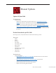
CDs or DVDs don’t show up on the Desktop 1. Select Preferences from the Finder menu and make sure the option to show CDs, DVDs and iPods is checked: in the General window as shown below.
iMac (24-inch Early 2008) iMac (24-inch Early 2008)
iMac (24-inch Early 2008) iMac (24-inch Early 2008)
No: Replace the optical drive. Does it burn correctly now? Yes: Problem solved. No: Replace the logic board. Optical drive does not accept CD / DVD disc The optical drive on this computer has narrow tolerances for the recommended optical media. If the drive does not accept discs, the wrong kind of disc could be inserted. 1. Open the computer and slowly lift the panel. Verify that the four inverter-to-panel-cables are not resting on top of the optical drive.
Disc will not eject 1. Verify disc is not in use by quitting any applications that may be using the disc. 2. Verify drive slot is not blocked, bent, compressed or damaged. 3. Press and hold Media Eject key at top right corner of keyboard. If that does not work, hold down Function (fn) key then Media Eject key in sequence, then together simultaneously. 4. Drag disc icon to trash, or select it and press Command-E. 5.
Fan Sound Fans running at full speed after the computer turns on 1. The customer may have entered a diagnostic mode that causes the fans to run at full speed.* Restarting the system will not restore normal fan operation. To solve the problem, the user or technician should follow instructions in the “General Information” chapter to reset the SMC: *Note: Customers reporting this symptom should be told to press the power button AFTER the power cord has been fully inserted.
System noisy, fails Apple Hardware Test for temp sensor 1. Check the error code against the Apple Hardware Test error code chart in this chapter. 2. Make sure the LCD temp sensor cable is connected to the sensor on the back of the LCD panel in the top right corner. 3. Make sure the LCD temp sensor cable is fully inserted into the connector on the bottom left side of the logic board.
Loud fan noise coming from inside the computer The iMac has a trio of fans that circulate air throughout the system. It also includes temperature sensors, and advanced thermal software that spins the fans fast or slow as needed. As the system usage increases, the fans will adjust their speed using advanced thermal software to meet the cooling needs of the system.
4. The normal functioning of the hard drive and optical drive will generate additional whirring and scratching noises that may be audible. We can isolate these noises by booting the computer to the iMac Install Mac OS X Install Disc 1. - Place the disc in the drive, and restart your machine while holding down the “C” key as the machine starts up. - Once at the Installer window, choose Open Disk Utility from the Installer Menu.
Audible buzzing, whining, or ticking noise The iMac contains several mechanical devices such as motors and fans that may make audible buzzing, ticking, or whining noises when they are operating in a normal manner. The sounds will vary depending on how the system is used. When troubleshooting abnormal noises try the following: 1. Verify that the computer is running a supported version of the Mac OS X operating system.
AirPort Not able to connect wirelessly with AirPort 1. From the Apple menu, choose About this Mac. 2- Click on More Info. System Profiler should open. 3- In System Profiler, in the column on the left, look under Network for a line called “AirPort Card”. Select that line. 4- Does the section to the right say “No Information Found”? Yes: The computer doesn’t realize it has an AirPort card installed. Go to step. 5 No: The iMac recognizes that it has an AirPort card installed. Go to step 6.
Bluetooth (also see Wireless Issues topic) Bluetooth devices won’t sync with my computer 1. Make sure the computer has a Bluetooth board installed. Open System Preferences (from the Apple menu, choose System Preferences) and verify that “Bluetooth” appears in the Hardware section of the window. 2. Locate the Bluetooth board inside the computer. Reseat the Bluetooth board, Bluetooth cable, and the Bluetooth antenna. 3 Turn on Bluetooth. In System Preferences, click Bluetooth and then click the Settings tab.
IR Remote Remote won’t communicate with system applications such as iTunes or iPhoto, or with the optical drive Make sure of the following when using the Apple Remote: • You are within 30 feet of the front of the computer. • You have an unobstructed line-of-sight to the front of the computer. • You are pointing the lens end of the Apple Remote directly at the front of the computer. • The computer is powered on and awake.
IR Sensor/Receiver Supported applications do not respond to input from the remote control 1. Perform the checks above under “IR Remote” to verify that the Apple Remote is functioning correctly, and retest. Do supported applications now respond to input from the IR remote? Yes: Problem resolved. No: Go to the next step. 2. Verify that the IR Sensor can be seen in the Apple System Profiler. Open the Apple System Profiler and click on the “USB” section.
Built-in iSight Camera The built-in camera is not recognized 1. Boot the computer to the desktop and launch iChat AV. Note: You do not need to be connected to a network to use iChat AV to troubleshoot. Verify that the correct versions of Mac OS X and iChat AV are installed. Reinstall or update software as needed. 2. Open the iChat AV preferences and click on the ‘Video’ icon. Verify whether the camera is recognized by the iChat AV software.
quality acceptable? Yes: The camera is functioning normally. The image quality problems may be caused by bandwidth limitations when using iChat over the internet. Instruct the customer to use the iChat AV connection doctor feature to verify that there is sufficient bandwidth to have a video iChat session without a significant degradation of image quality. No: The camera may not be functioning normally. Replace the front bezel for poor image quality.
Speakers Can’t hear sound from the speakers 1. Disconnect any external microphones, speakers, or headphones. 2. Access System Preferences and select Sound. In the Sound pane, select Output and make sure the Internal speakers are selected as the device for sound output, the Output volume is adequate, and Mute is not selected. Do you have sound now? Yes: Problem resolved. No: Go to the next step. 3. Reset parameter RAM. Press Command-Option-P-R during startup but before “Welcome to Macintosh” appears.
Mouse (also see Wireless Issues topic) The scroll bar on my mouse does not work in all directions See Knowledge Base article 302417, for instructions and a QuickTime movie demonstration on how to clean the scroll ball. My mouse doesn’t work at all 1. Turn over the mouse and check the if the red LED on the underside of the mouse. Is the LED lit? Yes: The mouse has power. Try using the mouse on another surface. Non-reflective, opaque surfaces without repetitive patterns work best.
Mouse tracking issues f your Mighty Mouse is covered in fingerprints or its surface has become soiled, it can be gently wiped with a clean lint-free cloth. If necessary, moisten the cloth using only water, making sure not to oversaturate it. Be aware that the mouse contains electronic components that may be damaged if water drips from the cloth into the mouse via the seam around the scroll ball or around its underside.
My keys are sticky or slow to respond 1. Try a known good keyboard. 2. Open System Preferences. Click on the keyboard and mouse icon. Adjust the “key repeat speed and delay until repeat” rate. 3. Replace the keyboard. When I type, strange characters appear on the screen 1. Depending on your iMac’s settings, a simple keystroke can change your keyboard from English to Japanese. This can result in some pretty funny characters showing up when you type. To switch to the US keyboard, 2.
Wireless Issues (also see Additional Wireless Topics) The aluminum Apple Wireless Keyboard will not turn on. 1. Confirm that the batteries are installed properly and the batteries are known good. 2. Open the battery compartment over. Make sure to install the positive and negative ends of the batteries in the keyboard as shown. The keyboard will not turn on if the batteries are incorrectly installed. 3. Replace the battery compartment cover. 4. Turn on the keyboard by pressing the Power On switch.
Can not set up the aluminum Apple Wireless Keyboard 1. Confirm that you have Mac OS X v10.4.10 or later installed and install the keyboard software update. If using Mac OS X 10.4.5 or later the keyboard software update is not needed. 2. Install the batteries. Use a coin to remove the battery compartment cover. 3. Slide the batteries into the battery compartment as shown below. Replace the battery compartment cover and leave the keyboard turned off. 4. Open the Bluetooth Setup Assistant. 5.
Assistant on the Apple Wireless Keyboard. Press the Return key on the keyboard when you are finished. 11. Once the assistant says the computer and keyboard have successfully paired, click Continue. 12. Setup is complete. Click Quit. The LED is flashing on the keyboard or mouse When your Apple Bluetooth mouse or keyboard is turned on, the light flashes twice in succession, and then repeats, (blink-blink-pause, blink-blink-pause).
Keyboard is not discoverable To pair your aluminum Apple Wireless Keyboard with your Macintosh computer, the keyboard needs to be in a ‘discoverable mode.’ Note: If you need to put the older Apple Wireless Keyboard in a discoverable mode for pairing, see the previous topic. Follow these steps to put the aluminum Apple Wireless Keyboard in a discoverable mode: 1. Open the Bluetooth Setup Assistant on your Mac: • For Mac OS X 10.4.10 or later • For Mac OS X 10.5 or later 2.
Some keys are working on the Wireless keyboard If some keys are working, but others behave as if the Caps Lock is “ON”, and the customer was using an extended keyboard (with a number pad), but switched to an Apple Wireless keyboard, check the following setting and try the wireless keyboard again. • Turn “Off” Mouse Keys under System Preferences-->Universal Access-->Mouse.
Bluetooth: How to Set Up Your Apple Wireless Mouse Refer to Knowledge Base document 86468 - Follow the instructions in this document to set up your Apple Wireless Mouse. Bluetooth: How to Se Up your wireless Mighty Mouse Refer to Knowledge Base document 303921 - Follow the instructions in this document to set up your Apple Wireless Mighty Mouse.
USB USB port is not recognizing known devices 1. Please unplug all of your USB devices from your iMac except your Apple Keyboard and Apple mouse. 2. Now plug your device directly into the back of your iMac. Does it work as expected now? Yes: Your device works when plugged directly into the computer. This indicates a conflict with one of the other USB devices.
Service Source Views iMac (24-inch Early 2008) © 2008 Apple Inc. All rights reserved.
iMac (24-inch Early 2008)—Upper Exploded View Camera 922-8457 Front Bezel 922-8471 Glass Panel, Cover 922-8469 LCD Assembly, 24” 661-4685 LCD Temp Sensor 922-8235 Cable Inverter, Power 922-8162 Cable, LCD Temp Sensor 922-8236 Cable, Optical Temp Sensor 922-8222 Clip, Temp Sensor, Pkg of 5 922-8183 Speaker, Left 922-8464 Hard Drive Clip 922-8470 Cable, HD Temp Sensor 922-8165 Hard Drive 661-4633 3.5”, 320 GB, 7200 661-4634 3.5”, 500 GB 7200 661-4635 3.5”, 750 GB, 7200 661-4636 3.
iMac (24-inch Early 2008)—Lower Exploded View Logic Board 661-4666 2.8 GHz 661-4667 3.
Screw Chart Screw Chart: Page 1 of 3 Note: Screws are not to scale.
Screw Chart: Page 2 of 3 922-7069 T10 922-8174 T10 922-7971 T10 AC power inlet to chassis ground (1) Stand to clutch mechanism Video card to heatsink support 922-8249 T10 922-7066 T10 922-8172 T8 Left speaker (1) Right speaker, (1) LCD display to rear cover (8) 922-8177 T8, 30mm 922- 8178 T8, 15mm 922-7020 T10 Front bezel to rear cover (2) Front bezel to rear cover (6) Clutch mechanism to chassis (4) 922-7656 T6 922- 8176 T10 19mm 922-7019 T8 Optical cable to optical drive (2) Front be
Screw Chart: Page 3 of 3 922- 8175 T8 922- 6800 T10 922-8173 T8 Logic board, each side of memory slot (2) Power supply to left P-wall (2) Power supply to rear cover (2) AC inlet to rear cover (3) Logic to rear cover Logic board standoff to rear cover (4) 922- 6842 T10, machine 922- 7001 T10 922-4723 T8 Logic board to backer board (1) Optical to chassis (2) Power supply to chassis (2) Hard drive pins (2) Video card to logic board (2) iMac (24-inch Early 2008) Views — Screw Chart 253