Service Source iMac (24-inch) Updated 29 October 2007 © 2006 Apple Inc. All rights reserved.
iMac (24-inch) Contents Take Apart General Information 6 What’s New 6 29 October 2007 6 23 April 2007 6 13 March 2007 6 22 February 2007 6 16 February 2007 6 January 2007 7 Product Views 7 How to identify your iMac 9 Note About Images in This Manual Tools Required 10 Orientation 10 Serial Number Location 10 Safety 11 Opening the Computer 12 EMI Shielding 13 Access Door 9 14 Memory 16 Front Bezel 19 Camera Board 23 Battery 27 Ambient Light Sensor (ALS) Board 30 IR (Infrared) Board 33 IR/ALS Cable 36 I
Ambient Temperature Sensor 46 Bluetooth Card 50 LCD Display Panel LVDS Cable 53 60 Inverter Cable 63 Speaker, Right 66 Optical Drive Fan 71 Power Supply, AC/DC Hard Drive 74 82 Hard Drive Sensor Cable CPU Fan 88 91 Optical Sensor Cable 95 Optical Drive 98 Optical Temperature Sensor 110 AirPort Extreme Card 113 Bluetooth Antenna Cable 120 Logic Board 125 Hard Drive Fan 141 Speaker, Left 144 Video Card 149 AC Power Inlet 156 Camera/Microphone Cable 160 AirPort Antennas 163 Clutch Cover 172 Clut
Hard Drive Data Cable 186 Rear Cover 189 Stand 192 Additional Procedures Installing the VESA Mount Link to Instructions 199 199 Retrieving the Clutch Mechanism 200 Troubleshooting General Information 207 Serial Number 207 DDR Memory 208 Diagnostic LEDs 210 Symptom Charts 212 Power Issues 213 No Video 214 Display 218 Hard Drive 219 Optical Drive 221 Fan Sound 226 AirPort 230 Bluetooth 231 IR Remote 232 IR Sensor/Receiver 233 Built-in iSight Camera 234 Speakers 236 Mouse 237 Keyboard 238 Error Beep(s)
Service Source Take Apart iMac (24-inch) © 2006 Apple Computer, Inc. All rights reserved.
General Information What’s New 29 October 2007 A note was added to the Logic Board Replacement section to tell service providers to install the iMac Firmware Update 1.2 (or later). • For proper performance and reliability of the Intel Core 2 Duo processors, apply the iMac firmware update after replacing the logic board. The firmware update allows Apple service to consolidate the version 1 and version 2 logic boards. Refer to KBase article: Firmware updates for Intel-based Macs.
January 2007 • The “No Power” symptom in Troubleshooting has been updated. If your computer won’t turn on, try removing and reinstalling the SO-DIMMs. December 2006 • When replacing the logic board, check that two spacers and a piece of aluminum tape have been installed in manufacturing. If the spacers are not present, refer to the logic board replacement procedure or inbox notice that ships with the logic board.
iMac (24-inch) Take Apart — General Information 8
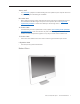
How to identify your iMac On the bottom of your iMac stand, you’ll find a label with the serial number printed on it: This label also provides the computer configuration and an “EMC” number (EMC No.). The EMC number for the iMac (24-inch) computer is 2111. The EMC number is unique for different iMac models. To confirm the configuration from the Apple menu, choose About This Mac. The Processor listing will show the speed of the processor followed by the processor type.
Tools Required The following tools are required to service the computer: • ESD-safe workstation and mat • Soft, clean towel or cloth (to protect the display and removed parts from scratches) • Access card (Apple part number 922-7172) • Black stick (or other nonconductive nylon or plastic flat-blade tool) • Phillips #1 screwdriver • Phillips #2 screwdriver • Torx T6 screwdriver (magnetized) • Torx T8 screwdriver (magnetized) • Torx T10 screwdriver (magnetized) • Flat-blade screwdriver • Needlenose pliers • P
Safety Warning: When the computer is under power, be aware that the power supply contains high voltages that pose a potential hazard to your personal safety. Never work on or near the power supply with the unit powered on; and as a further precaution, always make sure the unit is unplugged when working on it with the front bezel removed. WARNING: HIGH VOLTAGE Text or photographs marked by this symbol indicate that a potential hazard to your personal safety exists from a high voltage source.
Opening the Computer Only Apple authorized, desktop certified technicians should ever remove the front bezel on the computer. When the front bezel is removed, be sure to always ground yourself and follow ESDsafe repair practices.
EMI Shielding The rear cover of the computer is wrapped in EMI shielding that is easily torn and damaged. To maintain a properly shielded unit, you must repair all accidental tears and cracks to the shielding by covering them with EMI tape that can be found at your local electronics supplier.
Access Door Tools • • • Phillips #2 screwdriver ESD-safe workstation and mat Soft , clean towel or cloth Preliminary Steps Before you begin, place the computer face down so that the bottom is facing you.
Removing the Access Door 1. Raise the stand and use a Phillips #2 screwdriver to loosen the two captive access door screws. 2. Remove the access door. Replacing the Access Door 1. Lift the stand out of the way. 2. Position the access door on the rear housing over the memory compartment. 3. Use a Phillips #2 screwdriver to tighten the captive screws.
Memory This computer comes with a minimum of 512 MB of 667 GHz PC2-5300 Double Data Rate 2 (DDR2) Small Outline Dual Inline Memory Modules (SO-DIMMs). It has two slots that can accept DIMMs. The slots are stacked (top and bottom) on the logic board behind the access door. A 512 MB, 1 GB, or 2 GB memory module may be installed for a maximum of 3 GB of memory. Although you can install up to 4 GB of memory, the system supports no more than 3 GB.
Removing the Memory 1. Shut down the computer, and disconnect all cables including the power cord. 2. Holding the sides of the computer, lay it face down on a soft, clean cloth. 3. After removing the access door, touch the metal frame around the memory compartment to discharge any static electricity from your body. Important: Always discharge static before you touch any parts such as the memory board.
Replacing the Memory 1. Make sure the DIMM levers are all the way open. 2. With the computer face down, orient the DIMM with the notch on the left. 3. With your fingers, press the DIMM fully into the slot until you hear a click. 4. Do not use the DIMM levers to push in the DIMM. Trying to push the DIMM into the slot using the levers may damage the SDRAM DIMM. You’ll hear a slight click when the memory is fully seated. After the memory is fully seated, close the levers. 5.
Front Bezel Tools This procedure requires the following tools: • Torx T8 screwdriver • Soft, clean towel or cloth • Black stick (or other nonconductive nylon or plastic flat-blade tool) Preliminary Steps Before you begin, remove the access door.
Removing the Front Bezel 1. Place the computer on the rear cover with the stand facing you. 2. Tilt up the front bezel and remove the four screws along the bottom. 3. While holding the memory card levers closed (not protruding from the access door opening), start tilting up the lower end of the bezel.
4. With the lower corners loosened, lift up—but do not remove—the bezel. Caution: To prevent LCD panel damage, never press on the display face. 5. Lift up the top of the bezel and notice the connected microphone and camera cables. Without straining the cables, hold the bezel up, and disconnect the camera cable from the camera board and the microphone cable from the cable extension.
6. Lift the front bezel off the computer. Note that a replacement front bezel includes the following: • camera lens • camera board • camera board bracket • microphone cable • sensor • gaskets • slot-load drive felt • metal brackets Replacing the Front Bezel 1. When installing the front bezel, connect the camera and microphone cables and tuck the cables into the computer housing. Carefully lower the bezel onto the computer, and make sure the cables cannot be pinched. 2.
Camera Board Tools • • Torx T8 screwdriver ESD mat, soft , clean towel or cloth Preliminary Steps Before you begin, remove the access door , glass panel, and front bezel.
Removing the Camera Board 1. The camera board cable is visible after you remove the front bezel off the computer. 2. Remove two T8 screws on the camera board. 3. Lift the camera board out of the rear housing enough to access the camera cable. 4. Unwrap the kapton tape over the camera cable and connector. Disconnect the camera cable from the camera board, pulling the cable to the left.
Replacing the Camera Board 1. Connect the camera cable to the camera board. Reapply the kapton tape over the cable and connector. 2. Position the camera on top of the black posts (on the rear cover). 3. Replace the two T8 screws. 4. 5. 6. Connect the camera and microphone cables.
7. Reapply the tape across the length of the camera board. 8. Tuck the camera board cables neatly into the channel on the rear housing. 9. Holding the memory ejector levers closed, lower the font bezel down. 10. Replace the bezel screws along the bottom of the computer. 11. Replace the access door; tighten the two captive screws.
Battery Tools The only tool required for this procedure is a black stick (or other nonconductive plastic or nylon tool).
Removing the Battery 1. Use a black stick to pry out the battery from the battery socket on the logic board. 2. Before installing the battery, make sure the side with the engraved markings (+ side) is up .
Replacing the Battery 1. Make sure the battery socket is open and free of dust. 2. Press the battery into the socket. While holding the memory eject levers closed, replace the front bezel. 3. Replace the access door.
Ambient Light Sensor (ALS) Board Tools The only tool required for this procedure is a Torx T6 screwdriver.
Removing the ALS Board 1. Remove the 9-mm long T6 screw from the top right corner of the ALS board. 2. Tilt out the ALS board, and disconnect the IR/ALS cable from the board. Lift the ALS board from the IR board and IR shield.
Replacing the ALS Board 1. Connect the IR cable to the ALS board. 2. Install the ALS board and screw. 3. While holding the memory eject levers closed, replace the front bezel. 4. Replace the access door.
IR (Infrared) Board Tools The only tool required for this procedure is a Torx T6 screwdriver.
Removing the IR Board 1. Remove the two T6 screws from the top outer corners of the IR and ALS board. Set aside the square ALS board. 2. Tilt out the IR board, and disconnect the IR/ALS cable from the IR board. Lift the IR board from its IR shield.
3. Remove the IR board from the IR shield and logic board. Replacing the IR Board 1. Connect the IR cable to the IR board and ALS board. 2. Install the IR shield, IR board, ALS board, and screws. 3. While holding the memory eject levers closed, replace the front bezel. 4. Replace the access door.
IR/ALS Cable Tools The only tool required for this procedure is a black stick (or other nonconductive nylon or plastic flat-blade tool).
Removing the IR/ALS Cable 1. Remove the two screws from the IR and ALS boards: • 5-mm long T6 screw at left corner • 9-mm long T6 screw at right corner 2. Lift out the ALS board and disconnect the cable from the ALS board.
3. Lift out the IR board and disconnect the cable from the IR board. 4. Peel up the strip of tape that secures the cable to the logic board, and disconnect the other end of the cable from the logic board.
Replacing the IR/ALS Cable 1. Connect the cable to the IR board and ALS board before installing them into the IR/ALS shield. Position the shield over the logic board and install the two screws. 2. Connect the other end of the cable to the logic board. 3. Holding the memory eject levers closed, replace the front bezel. 4. Replace the access door.
IR/ALS Shield Tools The only tool required for this procedure is a black stick (or other nonconductive nylon or plastic flat-blade tool).
Removing the IR/ALS Shield With the ALS board and IR board removed, the shield is loose.
Replacing the IR/ALS Shield 1. Position the IR board and ALS board (with IR/ALS cable connected) into the IR/ALS shield. 2. Position the shield over the logic board and install the two screws. 3. Holding the memory eject levers closed, replace the front bezel. 4. Replace the access door.
Ambient Temperature Sensor Cable Tools The only tool required for this procedure is a black stick (or other nonconductive plastic or nylon tool).
Removing the Ambient Temperature Sensor Cable 1. Note the cable routing from the left speaker to the logic board. 2. Use a black stick to disconnect the cable from the sensor board on the speaker and the connector on the logic board. 3. Remove the cable.
Replacing the Ambient Temperature Sensor Cable 1. Connect the cable to the sensor board on the speaker and the logic board. 2. While holding the memory eject levers closed, replace the front bezel. 3. Replace the access door.
Ambient Temperature Sensor Tools • • Black stick (or other nonconductive nylon or plastic flat-blade tool) Permanent ink felt-tip pen Preliminary Steps Before you begin, remove the following: • Access door • Front bezel Part Location iMac (24-inch) Take Apart — Ambient Temperature Sensor 46
Removing the Ambient Temperature Sensor 1. Disconnect the ambient temperature sensor cable from the sensor board. 2. Check the position of the ambient temperature sensor on the left speaker. Use a permanent ink marker to draw an outline of the sensor.
3. Use a black stick to peel up the sensor from the adhesive on the side of the speaker. Replacing the Ambient Temperature Sensor 1. Replacement Note: If you are replacing the left speaker, use a permanent ink pen to mark the sensor area as a reference before installing the sensor. Note: A replacement left speaker includes the attached cable and gasket, but not the sensor.
2. Install the sticky side of the sensor on the speaker within the outlined marking. 3. Connect the temperature sensor cable. 4. Replace the display panel. 5. Replace the front bezel. 6. Replace the access door.
Bluetooth Card Tools • Torx T6 screwdriver Preliminary Steps Before you begin, remove the following: • Access door • Front bezel Part Location iMac (24-inch) Take Apart — Bluetooth Card 50
Removing the Bluetooth Card 1. Using a T6 torx screwdriver, remove the two 5-mm long screws from the lower left and upper right opposite corners of the Bluetooth card. Note: There is no need to disconnect the inverter cable to remove the Bluetooth card. 2. Lift the card from underneath the inverter cable and off of the logic board.
3. Disconnect the Bluetooth antenna from the left side of the card. Replacing the Bluetooth Card 1. Connect the Bluetooth antenna to the Bluetooth card. 2. Press the Bluetooth card onto the logic board connector. 3. Replace the two screws. 4. Replace the front bezel. 5. Replace the access door.
LCD Display Panel Tools • • • • Torx T6 screwdriver Torx T8 screwdriver Torx T10 screwdriver Black stick (or other nonconductive nylon or plastic flat-blade tool) Preliminary Steps Before you begin, remove the following: • Access door • Front bezel Part Location iMac (24-inch) Take Apart — LCD Display Panel 53
Removing the Display Panel 1. Place the computer with the display face up. 2. Remove the two T6 screws from the LVDS connector. 3. Disconnect the LVDS cable and inverter cable from the logic board.
4. Remove the eight 8-mm long T8 screws from the sides of the panel frame.
5. Peel up the strip of tape at the lower corners of the LCD panel.
6. Grasp the LCD panel at the bottom edge, and tilt up the panel to remove it from the computer assembly. 7. Note: If replacing the display panel, disconnect the LVDS cable from the panel and the inverter cable from the inverter board before returning the module to Apple. Transfer the two cables to the replacement panel. A replacement panel includes the inverter board, both display panel mounting brackets, the EMI strip surrounding the panel, and the foam strip and gaskets, as shown below.
Replacing the Display Panel 1. Connect the LVDS cable to the rear of the display panel. 2. Connect the inverter cable to the inverter board on the rear of the display panel. 3. Make sure the tape at each lower corner is back far enough so it cannot be pinched as you lower the LCD panel into the computer assembly.
4. Install the eight mounting screws. 5. Connect the LVDS cable connector to the logic board and secure it with two screws. 6. Connect the inverter cable to the logic board. 7. Replace the front bezel. 8. Replace the access door.
LVDS Cable Tools • • • Torx T6 screwdriver Black stick (or other nonconductive nylon or plastic flat-blade tool) Soft, clean towel or cloth Preliminary Steps Before you begin, remove the following: • Access door • Front bezel • LCD display panel Part Location iMac (24-inch) Take Apart — LVDS Cable 60
Removing the LVDS Cable 1. With the computer face down on a soft cloth, peel up the strips of tape from the LVDS cable on the back of the display panel. 2. Press in on the cable clips and then pull straight down on the cable to disconnect the LVDS connector. 3. Lift the LVDS cable from the display panel.
Replacing the LVDS Cable 1. Connect the LVDS cable to the rear of the display panel. 2. Replace the tape over the LVDS cable connector. 3. With both the LVDS cable and the inverter cable connected to the back of the display panel, install the display panel with eight mounting screws. 4. Connect the LVDS cable and the inverter cable to the logic board. 5. Replace the front bezel. 6. Replace the access door.
Inverter Cable Tools • • • Torx T6 screwdriver Black stick (or other nonconductive nylon or plastic flat-blade tool) Soft, clean towel or cloth Preliminary Steps Before you begin, remove the following: • Access door • Front bezel • LCD display panel Part Location iMac (24-inch) Take Apart — Inverter Cable 63
Removing the Inverter Cable 1. With the computer face down on a soft cloth, peel up the strips of tape that cover the inverter cable and connector on the back of the display panel. 2. Grasp the inverter cable close to the connector and disconnect it from the inverter board. 3. Lift the inverter cable from the display panel.
Replacing the Inverter Cable 1. Connect the inverter cable to the inverter board on the rear of the display panel. 2. With both the LVDS cable and the inverter cable connected to the back of the display panel, install the display panel with eight mounting screws. 3. Connect the LVDS cable and the inverter cable to the logic board. 4. Replace the front bezel. 5. Replace the access door.
Speaker, Right Tools • Torx T10 screwdriver Preliminary Steps Before you begin, remove the following: • Access door • Front bezel • LCD display panel Part Location iMac (24-inch) Take Apart — Speaker, Right 66
Removing the Right Speaker 1. Note the speaker cable routing before removing the speaker: The right speaker cable starts at the speaker body, tucks under the optical fan cable, down between the fan and the logic board, under the logic board, and connects to the top— inner—right corner of the logic board. 2. Peel up the EMI tape at the lower right corner of the speaker, and remove the 26-mm long screw from the right speaker.
3. Holding the opposite corners of the speaker, pull it up from the computer assembly. 4. Rest the speaker on the table as you disconnect the right speaker cable from the top right corner of the logic board.
5. Route the speaker cable between the fan and logic board and out from underneath the optical fan cable. 6. Note that a replacement right speaker includes the attached cable, gasket, and tape.
Replacing the Right Speaker 1. Tuck the speaker cable between the CPU fan and the logic board, and connect the speaker cable to the logic board. 2. Install the speaker in the computer assembly. 3. Secure the right speaker with the mounting screw, and reapply the EMI tape. 4. Replace the display panel. 5. Replace the front bezel. 6. Replace the access door.
Optical Drive Fan Tools • No tools are required to remove the optical drive fan.
Removing the Optical Drive Fan 1. Note the location of the two fan guide posts, right and left. The right post may be obscured by the speaker cable; however you do not have to discconnect the speaker cable to remove the fan. 2. Disconnect the fan cable from the logic board. 3. Holding the top edge of the fan, pull the body of the fan off of the guide posts on the rear cover.
Replacing the Optical Drive Fan 1. Before installing the fan, make sure the speaker cable and AirPort antenna cables in the rear cover are routed to the right of the guide post shown. 2. Lower the fan onto the guide posts in the rear cover. Connect the fan cable. 3. Replace the display panel. 4. Replace the front bezel. 5. Replace the access door.
Power Supply, AC/DC Tools • • Torx T10 screwdriver Black stick (or other nonconductive plastic or nylon flat-blade tool) Preliminary Steps Before you begin, remove the following: • Access door • Front bezel • LCD display panel Part Location iMac (24-inch) Take Apart —Power Supply, AC/DC 74
Removing the AC/DC Power Supply WARNING: The AC/DC power supply PCB remains powered up whenever the system is plugged in, whether or not the system has been turned on. Use extreme caution when troubleshooting the system with the front bezel removed. • Don’t work alone. In the event of an electrical shock it is important to have another individual present who can provide assistance. • Keep one hand in your pocket when working on any iMac (24-inch) system that is plugged in.
3. Position the computer assembly so you can see under the right side of the power supply. Tilt the power supply slightly and see how the adhesive plastic at the lower right corner of the body connects the power supply to the foam gasket and chassis. Use a black stick to wedge between the plastic and the chassis and pry up the lower corner. 4. Tilt the power supply to disconnect the lower right locking cable from the power supply.
5. Tilt back the power supply module, and use a black stick to free the adhesive on the power supply sleeve from the metal frame.
6. On the flip side of the power supply, note the adhesive areas that stick to the frame and chassis. 7. Note that a replacement power supply comes with the attached cable, mylar sleeve, foam gaskets, and adhesive strips.
Replacing the AC/DC Power Supply WARNING: The AC/DC power supply PCB remains powered up whenever the system is plugged in, whether or not the system has been turned on. Use extreme caution when troubleshooting the system with the front bezel removed. • Don’t work alone. In the event of an electrical shock it is important to have another individual present who can provide assistance. • Keep one hand in your pocket when working on any iMac (Early 2006) system that is plugged in.
2. On a new power supply, install the longest gasket first. Then make sure the two foam gaskets stick to each other and to the mylar sleeve before installing the power supply in the computer assembly. 3. On a new power supply, make sure the L-shaped foam gasket completely covers the lower right corner of the power supply. 4. Tilt up the power supply and install the lower and upper cables.
5. Replace the power supply screws. Install the machine screws (top right corner and bottom right corner) first when installing the power supply. 6. Replace the display panel. 7. Replace the front bezel. 8. Replace the access door.
Hard Drive Tools • • • Torx T10 screwdriver Torx T8 screwdriver (if removing clip from hard drive) Permanent ink, felt-tip pen Preliminary Steps Before you begin, remove the following: • Access door • Front bezel • LCD display panel Part Location iMac (24-inch) Take Apart — Hard Drive 82
Removing the Hard Drive 1. Disconnect the hard drive temperature sensor cable from the top of the logic board. Notice that the sensor cable runs under the foam gasket on the power supply. 2. Disconnect the power and data cables from right side of the hard drive. 3. Squeeze the black plastic clip at the top of the hard drive to loosen it from the chassis. 4. Tilt out the hard drive from the computer assembly.
5. If you are replacing the hard drive, remove the temperature sensor, screws, and clip to transfer to the replacement drive. 6. Replacement Note: Check the position of the temperature sensor. If you will be transferring it to a replacement drive, use a permanent ink pen to draw an outline of the sensor location. Refer to that marking when placing the sensor on a new hard drive. 7. Use a black stick to peel up the temperature sensor from the adhesive on the left end of the drive.
8. At the lower side of the drive, remove the two screw pins. 9. At the upper side of the drive, remove the two screws and the plastic clip.
Replacing the Hard Drive 1. If you are installing a new hard drive, transfer the screws, clip, and temperature sensor to the replacement drive. 2. Tilt the drive into the chassis and make sure it is secure in the chassis at the hard drive clip. 3. Connect the hard drive data and power cables to the hard drive. 4. Connect the hard drive temperature sensor to the logic board.
5. Make sure the temperature sensor cable runs under the foam gasket at the power supply. 6. Replace the display panel. 7. Replace the front bezel. 8. Replace the access door. 9. Important: After a new hard drive replacement, reinstall the operating system that shipped with the computer to ensure that it has the proper thermal management software.
Hard Drive Sensor Cable Tools No tools are required for this procedure.
Removing the Hard Drive Sensor Cable 1. Note the sensor cable routing. Disconnect the temperature sensor cable from its connector on the left end of the hard drive and on the top edge of the logic board. 2. Remove the sensor cable from under the foam gasket on the power supply.
Replacing the Hard Drive Sensor Cable 1. Connect the sensor cable to the hard drive and the logic board. Make sure the cable runs under the foam gasket on the power supply. 2. Replace the display panel. 3. Replace the front bezel. 4. Replace the access door.
CPU Fan Tools • Torx T10 screwdriver Preliminary Steps Before you begin, remove the following: • Access door • Front bezel • LCD display panel Part Location iMac (24-inch) Take Apart —Fan, CPU 91
Removing the CPU Fan 1. Remove the left speaker screw and peel up the EMI tape at the lower corner of the speaker. 2. Remove the body of the left speaker, and, without straining the speaker cable, rest the speaker on the table.
3. Disconnect the fan cable from the lower left corner of the logic board. 4. Pull out the fan from the guide posts on the rear cover.
Replacing the CPU Fan 1. Lower the fan onto the white guide posts in the rear cover. Push it down snug onto the posts. 2. Replace the left speaker. 3. Replace the display panel. 4. Replace the front bezel. 5. Replace the access door.
Optical Sensor Cable Tools • Torx T10 screwdriver Preliminary Steps Before you begin, remove the following: • Access door • Front bezel • LCD display panel Part Location iMac (24-inch) Take Apart — Optical Sensor Cable 95
Removing the Optical Sensor Cable Warning: Handle the optical drive at the side edges only. Do not touch or press anywhere else on the drive. 1. Note the sensor cable routing. Disconnect the temperature sensor cable from its connector near the optical fan on the logic board. 2. Disconnect the cable from the sensor on the top edge of the optical drive.
Replacing the Optical Sensor Cable 1. Replace the optical sensor cable. 2. Replace the display panel. 3. Replace the front bezel. 4. Replace the memory access door.
Optical Drive Tools • • • Torx T10 screwdriver Torx T6 screwdriver Needlenose screwdriver (with teeth) Preliminary Steps Before you begin, remove the following: • Access door • Front bezel • LCD display panel Part Location iMac (24-inch) Take Apart — Optical Drive 98
Removing the Optical Drive Warning: When servicing the optical drive, handle it by the edges only. Pressing elsewhere on the drive could damage its internal mechanism. 1. Note the sensor cable routing. Disconnect the temperature sensor cable from its connector near the optical fan on the logic board. 2. Disconnect the cable from the sensor on the top edge of the optical drive.
3. Peel up the tape from the flex cable, and note the routing of the sensor cable beside the flex cable. Use a black stick to push out on the two cable locks on the logic board, then pull the flex cable toward the drive to disconnect the flex cable from the logic board.
4. Locate the two black release levers on the mounting bracket. Using a needlenose pliers bend the lever toward the center of the drive. Pressing inward unhooks the lever from the chassis. Repeat the process to unhook the other release lever.
5. Squeeze the clips toward each other to unhook the drive from the chassis.
6. Peel back the strip of EMI mesh tape that anchors the bezel end of the drive to the rear cover. 7. Tilt up the optical drive, and lift it out of the computer assembly.
8. Replacement Note: Check the position of the temperature sensor. If you will be transferring it to a replacement drive, use a permanent ink marker to draw an outline of the sensor location. Refer to that marking when placing the sensor on a new optical drive. 9. Use a black stick to peel up the temperature sensor from the adhesive on the bottom of the drive.
10. If you are replacing the optical drive, transfer the flex cable (two 4-mm long T6 shoulder screws) and sensor to the replacement drive. The replacement drive includes the plastic mounting brackets, slot-load bezel, and gaskets.
11. Before installing the optical drive, make sure the cables on the right side of the rear cover are routed as shown.
Replacing the Optical Drive 1. Install the flex cable onto the optical drive with two T6 screws. 2. Connect the optical sensor cable to the drive. 3. Insert the optical drive bezel into the rear housing, lining up the bezel with the slot opening. Be sure to align the two guide holes in the slot-load bezel with the guide posts at each end of the rear cover slot.
4. Push down on the mounting brackets clips to lock the optical drive securely into place on the chassis. Caution: Never press down on or grasp the body of the optical drive when installing it. Pressing or squeezing the body of the optical drive could damage the drive mechanism. 5. Connect the flex cable to the logic board 6. Connect the optical sensor cable to the logic board.
7. Reattach the strip of mesh EMI tape over the optical drive near the slot end of the drive. 8. Replace the display panel. 9. Replace the front bezel. 10. Replace the access door.
Optical Temperature Sensor Tools • • Torx T10 screwdriver Permanent ink felt-tip pen Preliminary Steps Before you begin, remove the following: • Access door • Front bezel • LCD display panel • Optical drive Part Location iMac (24-inch) Take Apart — Optical Temperature Sensor 110
Removing the Optical Temperature Sensor Warning: Handle the optical drive at the side edges only. Do not touch or press anywhere else on the drive. 1. With the optical drive removed, check the position of the temperature sensor. Use a permanent ink marker to draw an outline of the sensor location. Refer to that marking when placing the sensor on a new optical drive. 2. Use a black stick to peel up the temperature sensor from the adhesive on the bottom of the drive.
Replacing the Optical Temperature Sensor 1. Place the replacement temperature sensor onto the optical drive. Make sure that the cable connector is positioned toward the cable. 2. Replace the optical drive. 3. Replace the optical sensor cable. 4. Replace the display panel. 5. Replace the front bezel. 6. Replace the memory access door.
AirPort Extreme Card Tools • • Torx T6 screwdriver Torx T10 screwdriver Preliminary Steps Before you begin, remove the following: • Access door • Front bezel Part Location iMac (24-inch) Take Apart — AirPort Extreme Card 113
Removing the AirPort Extreme Card 1. Remove the 26-mm long screw from the right speaker, and peel up the EMI tape from the lower right corner of the speaker. 2. Without straining the speaker cable, pull up the speaker body and rest it on the table.
3. Using a T6 torx screwdriver, remove the two 5-mm long screws and disconnect the two antenna cables from the AirPort Extreme card. 4. If the card does not pop up when the screws are removed, use your thumb to gently tilt the card up.
5. Holding the card by the edges, pull the AirPort Extreme card out of the slot, and disconnect the antenna cables.
Replacing the AirPort Extreme Card 1. See the following section on compatibility to order the replacement part by EEE code. 2. Connect the antenna cables to the connectors on the AirPort Extreme card. Note: The antenna cables might include an “L” or “R” tab near the connector end; however, you can disregard that because the cable position can be swapped without any change in performance. 3. Align the AirPort Extreme card with the slot on the logic board. Insert the board into the slot. 4.
Locating the EEE Code To locate the EEE code on the AirPort Extreme card, remove the card from the logic board. Turn the card over, and look for the representative EEE code within the card’s serial number. Locate the last four digits in the serial number. Drop the last digit (in this case, the letter “A”). The EEE code is the next three digits. In this case it’s “VZL”, shown below. To locate the EEE code on the logic board, locate the memory slot inside the computer.
EEE Code Table Use the table below to identify the logic board and AirPort Extreme card EEE codes for the iMac system. Order the correct service part based upon the corresponding EEE code. The table is available in Knowledge Base article 305112 - iMac (Late 2006): AirPort Card Differences. iMac Model Logic Board Part # Logic Board EEE Code AirPort AirPort Extreme Card Extreme Card Part # EEE Code iMac 24-inch 661-4182, Board , Logic, 2.
Bluetooth Antenna Cable Tools • Black stick (or other nonconductive nylon or plastic flat-blade tool) Preliminary Steps Before you begin, remove the following: • Access door • Front bezel • LCD display panel • CPU fan Part Location iMac (24-inch) Take Apart —Bluetooth Antenna 120
Removing the Bluetooth Antenna 1. Note that only the cable end of the Bluetooth antenna is visible as it exits the EMI shielding. 2. Disconnect the antenna from the Bluetooth board. 3. Carefully peel back the long strip of EMI tape from the lower left corner of the rear cover, as shown below.
4. Open the “sleeve” of the EMI backing to access the rest of the antenna cable. 5. Use a black stick to pry up the rectangular end of the antenna from the rear housing. Pull the remaining antenna cable through the opening in the EMI sleeve.
6. Remove the Bluetooth antenna from the rear cover. Note: The Bluetooth antenna includes the gasket material as shown. Replacing the Bluetooth Antenna 1. Press the sticky side of the antenna board to the housing until securely fastened. 2. Make sure the antenna cable runs under the gray foam material.
3. Close the EMI sleeve, and secure the opening with a strip of EMI tape. 4. Connect the Bluetooth antenna to the Bluetooth board. 5. Replace the CPU fan. 6. Replace the display panel. 7. Replace the front bezel. 8. Replace the access door.
Logic Board Tools • Torx T10 screwdriver Preliminary Steps Before you begin, remove the following: • Access door • Front bezel • LCD display panel • Speaker, right Part Location iMac (24-inch) Take Apart — Logic Board 125
Removing the Logic Board 1.
2. Remove the eight T10 screws from the logic board. 3. Note that the three machine screws on the backer plate have an arrow designation.
4. Remove the two screws at the support bracket. 5. Peel up the power supply gasket material where it overlaps the backer plate.
6. Tilt the logic board up and out—away from the memory card levers. Important: When handling the logic board, never handle the board by the heatsink or metal frame. 7. When the board is removed, check that the two washers on the processor side of the logic board did not fall off. .
8. Remove the video card before returning the board to Apple.
Replacing the Logic Board Replacement Note: iMac Firmware Update 1.2 (or later) Required For proper performance and reliability of the Intel Core 2 Duo processors, apply the iMac firmware update after replacing the logic board. Refer to KBase article: Firmware updates for Intelbased Macs. 1. See the following section on compatibility to order the replacement part by EEE code. 2. If you removed the logic board to access another module, reinstall the board as is.
3. Check the board for two spacers. If they are not already present, install the spacers and aluminum tape on the logic board (see steps 3-6). If they are present, go on to step 7. 4. Peel off the backing on the spacer. Place one spacer on the logic board at the location circled below.
iMac (24-inch) Take Apart — Logic Board 133
5. The second spacer and the strip of aluminum tape are installed on the white screw post in the rear housing at the location circled below. 6. Place the second spacer on top of the white screw post in the rear housing.
7. Attach the strip of aluminum tape to the rear housing EMI shielding and run the tape up the white screw post and over the spacer (see inset below). 8. Install the video card on the replacement logic board. 9. Position all the logic board cables out of the way so the logic board can be placed into the rear cover. 10. As you lower the board into the rear housing, make sure the memory levers are lowered through the access door opening and the logic board screw holes line up with the board.
11. At the left side of the heatsink, replace the two screws attaching the logic board support bracket to the chassis.
12. Connect the cables.
13. Replace the three machine screws first; then replace the five self-tapping screws. Note: In the following image, the letter “M” represents the machine screws. 922-7814 922-6800 14. Replace the display panel. 15. Replace the front bezel. 16. Replace the access door. Checking Compatibility between Logic Board and AirPort Card The iMac (Late 2006) computers were built with a number of logic boards and AirPort Extreme cards.
Locating the EEE Code To locate the EEE code on the AirPort Extreme card, remove the card from the logic board. Turn the card over, and look for the representative EEE code within the card’s serial number. Locate the last four digits in the serial number. Drop the last digit (in this case, the letter “A”). The EEE code is the next three digits. In this case it’s “VZL”, shown below. To locate the EEE code on the logic board, locate the memory slot inside the computer.
EEE Code Table Use the table below to identify the logic board and AirPort Extreme card EEE codes for the iMac system. Order the correct service part based upon the corresponding EEE code. The table is available in Knowledge Base article 305112 - iMac (Late 2006): AirPort Card Differences. iMac Model Logic Board Part # Logic Board EEE Code AirPort AirPort Extreme Card Extreme Card Part # EEE Code iMac 24-inch 661-4182, Board , Logic, 2.
Hard Drive Fan Tools No tools are required to remove the hard drive fan.
Removing the Hard Drive Fan Once the logic board has been removed, the fan will already be disconnected. Lift the fan straight up and off of the three guide posts.
Replacing the Hard Drive Fan 1. Before installing the hard drive fan, make sure the guide posts are not blocked. 2. Replace the logic board. 3. Replace the right speaker. 4. Replace the display panel. 5. Replace the front bezel. 6. Replace the access door.
Speaker, Left Tools • • Torx T10 screwdriver Permanent ink, felt-tip pen Preliminary Steps Before you begin, remove the following: • Access door • Front bezel • LCD display panel • CPU fan • Speaker, right • Logic board Part Location iMac (24-inch) Take Apart — Speaker, Left 144
Removing the Left Speaker 1. Using a T10 torx screwdriver, remove the 38-mm long screw from the left speaker. Replacement Note: The longer of the two speaker mounting screws is used to secure the left speaker; the shorter (26-mm long)screw secures the right speaker. 2. Peel up the EMI shield and tape from the left side and lower left corner of the speaker. 3. Loosen the speaker from the computer assembly. 4. Remove the CPU fan. 5. Remove the logic board.
6. Note that the left speaker cable runs under the length of the logic board, between the chassis and rear cover, and connects to the top right corner of the logic board. 7. With the logic board removed, peel up the tape that secures the speaker cable between the chassis and the EMI shielding.
8. Replacement Note: Notice that the left speaker body includes an ambient temperature sensor and attached cable. Check the position of the sensor. If you will be transferring it to a replacement speaker, use a permanent ink marker to draw an outline of the sensor location. Refer to that marking when placing the sensor on a new left speaker. Refer to Ambient Temperature Sensor in this chapter.
4. Replace the CPU fan. 5. Install the speaker in the computer assembly. Secure the left speaker with the longer of the two speaker mounting screws. 6. Connect the ambient temperature connector to the logic board. 7. Replace the display panel. 8. Replace the front bezel. 9. Replace the access door.
Video Card Tools • Torx T10 screwdriver Preliminary Steps Before you begin, remove the following: • Access door • Front bezel • LCD display panel • CPU fan • Speaker, right • Logic board Part Location iMac (24-inch) Take Apart — Video Card 149
Removing the Video Card 1. Remove the two 8-mm long machine screws. Be sure to retain these screws for reinstallation. 2. At the far right end of the video card heatsink, remove the 4-mm long support screw. Be sure to retain this screw for reinstallation.
3. Tilt up the video card with attached heatsink, and disconnect it from the card connector on the logic board. 4. When handling the video card, hold it by the heat pipe brace.
5. Be sure to retain the two plastic spacers on the video card area of the logic board. 6. Note that a replacement video card includes a temperature sensor and cable. Make sure these are pre-installed on the card before you replace the video card. (The sensor cable runs under the foam strip.
Replacing the Video Card 1. Make sure that video card includes a temperature sensor and cable. (The sensor cable runs under the foam strip.) 2. Install the two plastic spacers on the video card area of the logic board, and make sure they remain in place as you install the video card on the logic board.
3. Connect the video card to the logic board, and install the three screws.
4. Replace the logic board. 5. Replace the speakers. 6. Replace the display panel. 7. Replace the front bezel. 8. Replace the access door.
AC Power Inlet Tools • Torx T10 screwdriver Preliminary Steps Before you begin, remove the following: • Access door • Front bezel • LCD display panel • Power supply • CPU fan • Speaker, right • Logic board Part Location iMac (24-inch) Take Apart — AC Power Inlet 156
Removing the AC Power Inlet 1. Note the cable routing between the chassis frame and the rear cover. 2. Using a torx T10 screwdriver, remove the three 7-5-mm long self-tapping screws from the power inlet and the 5-mm long machine screw from the ground cable . Remove the EMI tape on the metal case.
3. Route the cable out from under the chassis, and remove the AC power inlet. Replacing the AC Power Inlet 1. Install the AC power inlet on the rear housing screw mounts with three self-tapping screws. 2. Install the power inlet ground cable to the chassis with a machine screw.
3. Route the power inlet cable beneath the chassis. 4. Using the EMI tape, securely tape the top and bottom edges of the AC power inlet to the rear housing. 5. Make sure that the screw on the left end of the AC power inlet is covered by the EMI tape. 6. Replace the power supply, and connect the AC power inlet cable. 7. Replace the logic board. 8. Replace the display panel. 9. Replace the IR Board. 10. Connect the antennas. 11. Replace the front bezel. 12. Replace the memory access door.
Camera/Microphone Cable Tools No tools are required to remove the camera/microphone cable.
Removing the Camera/Microphone Cable 1. Route the cable up through the cable channel on the rear cover. 2. At the top of the rear cover, peel back the tape that secures the cable onto the chassis. 3. Route the rest of the cable out from under the chassis.
Replacing the Camera/Microphone Cable 1. Insert the two-headed end of the camera cable through the access hole in the upper EMI shield. 2. Route the camera cable as shown below. Tape the camera cable to the rear housing. 3. Replace the optical drive, flex drive cable and screws, and optical drive sensor cable. 4. Replace the logic board. 5. Replace the speakers. 6. Replace the display panel. 7. Replace the front bezel. 8. Replace the access door.
AirPort Antennas Tools • Black stick (or other nonconductive nylon or plastic flat-blade tool) Preliminary Steps Before you begin, remove the following: • Access door • Front bezel • LCD display panel • Optical drive fan • Optical drive • Speaker, right • Logic board Part Location iMac (24-inch) Take Apart — AirPort Antennas 163
Removing the AirPort Antennas 1. At the top of the rear cover, note the location and placement of the left antenna board. 2. At the top of the rear cover, pry up the left antenna board with a black stick and carefully peel up the EMI shielding to unroute the left antenna board and attached gray cable.
3. At the top of the rear cover, note the location and placement of the right antenna board. 4. At the top right corner of the rear cover, pry up the right antenna board. Carefully pull up both antenna cables from under the edge of the EMI shielding.
5. Note how the cables are routed at the right corner of the chassis. 6. Continue to route the antenna cables from underneath the EMI shielding. However, because the shielding runs up the entire right side of the rear housing, you must carefully peel back the right side of the EMI shielding (including the slot-load drive opening).
7. Underneath the EMI shielding at the slot-load opening, peel up the two clear strips of tape that secure the antenna cables directly to the rear cover. Do not tug on the cables. 8. Down near the lower right corner where the antenna cables exit the EMI shielding, peel up the single strip of aluminum tape.
9. At the lower right corner on the underside of the EMI shielding, use a black stick to carefully guide the remaining section of the cables out through the opening in the shielding.
Replacing the AirPort Antennas 1. Insert the antenna connector end of the cables through the opening in the EMI shielding. 2. Secure the noninsulated section of the cables to the EMI shielding with the single strip of aluminum tape. 3. Follow the removal instructions in reverse to route the antenna cables up the right side of the rear cover and underneath the EMI shielding.
4. When securing the right antenna board, make sure the edge of the board fits directly beside the vertical ridge on the rear cover. 5. When securing the left antenna board, make sure the edge of the board fits directly beside the vertical ridge on the rear cover.
Note: When positioned correctly, the antenna board and gasket area should resemble the following images: 6. Replace the optical fan. 7. Replace the logic board. 8. Replace the right speaker. 9. Replace the optical drive. 10. Replace the display panel. 11. Replace the front bezel. 12. Replace the access door.
Clutch Cover Tools No tools are required for this procedure.
Removing the Clutch Cover 1. Peel up the EMI tape from the top, bottom, and sides of the clutch cover. 2. Lift the cover off of the clutch mechanism.
Replacing the Clutch Cover 1. Replace the metal clutch cover, and make sure the EMI tape holds the top, bottom, and sides of the cover onto the mechanism and rear cover. 2. Replace the logic board. 3. Replace the speaker. 4. Replace the CPU fan. 5. Replace the display panel. 6. Replace the front bezel. 7. Replace the access door.
Clutch Mechanism Tools • Torx T10 screwdriver Preliminary Steps Before you begin, remove the following: • Access door • Front bezel • LCD display panel • Power supply • CPU fan • Speaker, right • Logic board • Clutch cover • Stand Part Location iMac (24-inch) Take Apart — Clutch Mechanism 175
Removing the Clutch Mechanism 1. Using a torx T10 screwdriver, remove the four clutch mounting screws. 2. Peel back the mesh tape on top of the mechanism.
3. Lift the mechanism out of the rear cover. For your reference, front (top image) and back (bottom image) views are shown below).
Replacing the Clutch Mechanism 1. Make sure the stand is upright, and the end of the stand is inserted through the mounting hole in the rear housing. 2. Position the clutch on the stand, with the clutch springs at bottom. Install the eight long, clutch-to-stand mounting screws. 3. Adjust the clutch so that its chassis mounting holes align, and install the four screws that secure the clutch to the chassis. 4. Replace the mesh tape on top of the mechanism, press it into place. 5.
13. Insert the access card as far as it will go. Gently lift the stand approximately two inches to unlock the clutch mechanism, and then remove the access card. The clutch mechanism should now be unlocked.
Hard Drive Temperature Sensor Tools • • Torx T10 screwdriver Permanent ink felt-tip pen Preliminary Steps Before you begin, remove the following: • Access door • Front bezel • LCD display panel • Hard drive Part Location iMac (24-inch) Take Apart — Hard Drive Temperature Sensor 180
Removing the Hard Drive Temperature Sensor 1. Before removing the temperature sensor, use a permanent ink pen to draw an outline of the sensor location. Refer to that marking when placing the new sensor on the hard drive. 2. Use a black stick to peel up the temperature sensor from the adhesive on the left end of the drive.
Replacing the Hard Drive Temperature Sensor 1. Adhere the new temperature sensor to the hard drive. 2. Install the hard drive. 3. Replace the display panel. 4. Replace the front bezel. 5. Replace the access door.
Power Supply Cable Tools • • Torx T10 screwdriver Wire cutters Preliminary Steps Before you begin, remove the following: • Access door • Front bezel • LCD display panel • Power supply • CPU fan • Speaker, right • Logic board Part Location iMac (24-inch) Take Apart — Power Supply Cable 183
Removing the Power Supply Cable 1. Using a T10 screwdriver, remove the screws from the cable channel, and cut the cable tie. 2. Disconnect the power supply cable from the hard drive, and route the cable up through the cable channel and out from under the hard drive. Replacement Note: When reinstalling the cable, make sure the end with the hard drive power connector is routed over the chassis, while the end with the power supply connector is routed under the chassis and behind the hard drive.
Replacing the Power Supply Cable 1. Install the power supply cable through the cable channel and chassis, and replace the screws and cable tie. 2. Replace the CPU fan. 3. Replace the logic board. 4. Replace the speakers. 5. Replace the display panel. 6. Replace the front bezel. 7. Replace the access door.
Hard Drive Data Cable Tools • • Torx T10 screwdriver Wire cutters Preliminary Steps Before you begin, remove the following: • Access door • Front bezel • LCD display panel • Power supply • CPU fan • Speaker, right • Logic board Part Location iMac (24-inch) Take Apart — Hard Drive Data Cable 186
Removing the Hard Drive Data Cable 1. Using a T10 screwdriver, remove the screws from the cable channel, and cut the cable tie. 2. Disconnect the hard drive data cable from the hard drive, and route the cable down through the cable channel.
Replacing the Hard Drive Data Cable 1. Install the hard drive cable through the cable channel, and replace the screws and cable tie. 2. Replace the CPU fan. 3. Replace the logic board. 4. Replace the speaker. 5. Replace the display panel. 6. Replace the front bezel. 7. Replace the access door.
Rear Cover Tools No tools are required to remove the rear cover.
Part Location Removing the Rear Cover With all of the preliminary steps performed, the rear cover is the remaining assembly.
Replacing the Rear Cover 1. Replace the stand. 2. Replace the clutch. 3. Replace the left speaker. 4. Replace the logic board. 5. Replace the hard drive and optical drive fans (if removed). 6. Replace the optical drive. 7. Replace the hard drive. 8. Replace the right speaker. 9. Replace the CPU fan. 10. Replace the power supply. 11. Replace the display panel. 12. Replace the front bezel. 13. Replace the memory access door.
Stand Tools • • • Access card Torx T10 screwdriver Soft, clean cloth Preliminary Steps No preliminary steps are required before you begin.
Removing the Stand 1. Place the computer face down on a table so that the base of the stand extends over the table edge. Press the stand down and insert an access card into the slot between the top of the stand and the rear housing. 2. Insert the card as far as it will go, and press the stand down until you hear a click—the audible cue that tells you that the stand is locked into place.
3. Remove the access card, and remove the eight T10 clutch-to-stand screws. 4. Separate the stand from the clutch mechanism and rear housing.
Replacing the Stand 1. Align the pin on the clutch mechanism to the central hole in the stand. 2. Position the stand on the clutch mechanism. Install the eight mounting screws. 3. Place the computer face down on a table so that the base of the stand extends over the table edge. Press the stand down and insert an access card into the slot between the top of the stand and the rear housing.
4. Insert the access card as far as it will go. Gently lift the stand approximately two inches to unlock the clutch mechanism, and then remove the access card. The clutch mechanism should now be unlocked.
iMac (24-inch) Take Apart — Stand 197
Service Source Additional Procedures iMac (24-inch) © 2006 Apple Computer, Inc. All rights reserved.
Installing the VESA Mount Link to Instructions For instructions on removing the stand and installing the VESA mount adapter, refer to http://manuals.info.apple.com/en/iMac_24inch_VesaMountAdapter_InstallGuide.
Retrieving the Clutch Mechanism Overview Without a stand or VESA mount installed, the clutch mechanism can retract inside the computer only if an access card trips the latch that locks the clutch mechanism. To prevent this unlikely event, do not insert an access card into the slot on the back of the computer unless instructed to do so. In the rare event that retrieving the clutch mechanism is necessary, follow this procedure.
Procedure 1. Cut an access card vertically so that you have two halves of approximately the same size. 2. Collect the required tools. In addition to a soft cloth, you need one-half of an access card and the clutch mechanism retrieval tool (Apple part number 922-7849).
3. Place the computer face down on a soft, clean cloth. 4. Peer into the stand slot so you can see the recessed latch. The latch is a metal spring clip located above the clutch mechanism that is almost as wide as the stand slot.. 5. Insert the access card into one end of the stand slot and push the latch away from you. (When the latch moves, you feel the moderate resistance of the latch spring.
6. Now that you can sense how the latch moves, remove the access card and notice the shape of the clutch mechanism retrieval tool. 7. Important: When inserting the clutch mechanism retrieval tool, make sure the curved end of the tool is down, as shown. 8. Note that the small round opening on the end of the clutch mechanism retrieval tool must hook onto the pin on the recessed clutch mechanism.
9. Holding the access card so that the latch is pushed away as far as possible, use your other hand to insert the clutch mechanism retrieval tool into the slot. 10. Align the clutch mechanism retrieval tool over the pin on the clutch mechanism until the tool has a firm hold of the clutch mechanism. 11. If possible, have an assistant firmly hold down the computer as you simultaneously push the latch away and pull the mechanism toward you, as shown below.
12. When you can pull up the clutch mechanism and easily see it emerge through the slot, maintain the pull force on the clutch mechanism retrieval tool, but remove the access card. 13. With the access card removed, pull up the mechanism the rest of the way. 14. The clutch mechanism is now locked into place and ready to accept the installation of the stand or VESA mount.
Service Source Troubleshooting iMac (24-inch) © 2006 Apple Computer, Inc. All rights reserved.
General Information Serial Number The serial number for the iMac (24-inch) model is located on the bottom of the computer stand. Power On Self Test (POST) Intel-based Mac computers such as the iMac (24-inch) rely on a combination of tones and blinking LEDs to display Power On Self Test (POST) error codes.
• The solution to both of these situations is to first re-seat the memory and test the computer again. If the memory fails the POST test again, try memory that has been verified to work correctly on another system (i.e., “known-good”) or order new memory. DDR Memory The iMac (24-inch) computer has two SDRAM slots in the bottom of the computer. The iMac ships from the factory with at least 512 MB of DDR2 SDRAM installed in the top slot.
How to Reset the System Management Controller (SMC) The System Management Controller (SMC) is a chip on the logic board that controls all power functions for your computer. If your computer is experiencing any power issue, resetting the SMC may resolve it. The SMC controls several functions, including: • Telling the computer when to turn on, turn off, sleep, wake, idle, and so forth. • Handling system resets from various commands. • Controlling the fans. Note that resetting the SMC does not reset the PRAM.
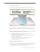
Diagnostic LEDs The iMac (24-inch) has four built-in diagnostic LEDs and a front LED on the main logic board that can help you to troubleshoot the computer. The four LEDs are located to the right of the memory slot. To Access the LEDs: 1. Follow the take apart instructions to remove the memory access door and front bezel. 2. The four troubleshooting LEDs 1, 2, 3, and 4 (numbered bottom to top) are in a column located to the right of the memory slot. Peel back the tape to view the LEDs.
when the computer is communicating properly with the video card. If LEDs 1 and 2 are ON and you heard the startup sound, but LED 3 is OFF, then the video card might be installed incorrectly or need replacement. LED #4 • Indicates that the computer and the LCD display are communicating. This LED will be ON when the computer is turned on and video signal is being generated. If the LED is ON and there is no display on the panel, the panel or inverter might be installed incorrectly or need replacement.
Symptom Charts How to Use the Symptom Charts The Symptom Charts included in this chapter will help you diagnose specific symptoms related to the product. Because cures are listed on the charts in the order of most likely solution, try the cures in the order presented. Verify whether or not the product continues to exhibit the symptom. If the symptom persists, try the next cure. Note: If a cure instructs you to replace a module, reinstall the original module before you proceed to the next cure.
Power Issues No Power The computer will not turn on. The display remains black and there are no sounds from the fans or drives. 1. Verify the power outlet is good. Plug a different device into the socket to ensure there is power, or plug the iMac into another outlet. Does the iMac power on now? Yes: Resolved. Bad outlet. No: Go on to the next step. 2. Check the power cord. Use a known good power cord. Does the iMac power on now? Yes: Your power cord has failed. Replace the AC power cord.
8. Press the power button. Check to see if LED # 2 comes On, comes on momentarily, or stays Off. LED # 2 is On: The Power Supply is functioning. Go on to the next step. LED # 2 comes on momentarily or stays Off: Replace the Power Supply. 9. At this point in the Power On process, you should hear a boot chime and see that LED #1 and #2 are On. Do you hear a boot chime? Yes: The power systems of the computer are working correctly. See “Troubleshooting No Video” in this chapter.
2. Reset your computer’s PRAM (Parameter RAM): -- If your iMac is on, turn it off by holding the power button until the unit powers off. You should hear the fans go quiet. -- While the computer is off, with your left hand, hold down the Apple key, the Option key next to it, and the letter “R” key on the keyboard. When you have these keys all pressed down, push the power button with your right hand and then quickly move that hand to hold down the letter “P” on the keyboard.
to generate video. Replace the main logic board. 7. If video is displayed normally on an external display but not on the iMac internal display panel, replace the LCD display.
Display is tinted another color. 1. Reset the parameter RAM. Press the Command-Option-P-R keys. When you keep all the keys held down, you will hear the startup chime over and over again (about every ten seconds) until you let go. After you hear the second chime, you can let go of the keys. Does the computer display video after successfully resetting the computer’s PRAM? Yes: Problem resolved. Restart the computer from the Apple menu and make sure the computer display is no longer tinted another color.
Display When displaying a single color over the screen area, the LCD panel shows one or more pixels that are not properly lit. Active-matrix LCD technology uses rows and columns of addressable locations (pixels) that render text and images on screen. Each pixel location has three separate subpixels (red, green, and blue) that allow the image to be rendered in full color. Each subpixel has a corresponding transistor responsible for turning the subpixel on or off.
Hard Drive Flashing question mark, or an alternating question mark and Mac OS (face or a folder) Note: When troubleshooting hard drive problems it is a good idea, if possible, to back up any important data. Some troubleshooting steps may require erasing the contents of the hard drive. 1. Boot from the system CD that came with the computer, and open Disk Utility. Does the hard drive show in Disk Utility? Yes: Run Repair Disk and Repair Permissions to correct any directory and permissions issues.
System hangs during normal startup process. 1. Boot from the system CD that came with the computer. Use Disk Utility to verify the hard drive. 2. Using Disk Utility, reformat the hard drive. 3. Check all cable connections to and from the hard drive. 4. Replace the hard drive data cable. 5. Replace the hard drive. 6. Replace the logic board.
Optical Drive CDs or DVDs don’t show up on the Desktop. 1. Select Preferences from the Finder menu and make sure the option to show CDs, DVDs and iPods is checked: in the General window as shown below.
2. Select System Preferences from the Apple menu and open the CDs & DVDs preferences window. Make sure that audio CDs are set to launch iTunes and movie DVDs set to launch DVD Player when those media are inserted, as shown below. 3. Check that the drive can read discs normally. Insert an audio CD and check whether it shows up on your desktop or launches iTunes. Does the audio CD mount on the desktop or in iTunes? Yes: The drive seems to read CD discs okay. Go on to Step 4.
The computer won’t burn discs. 1. Check whether the drive can read CDs and DVDs normally. Perform the steps above for “CDs or DVDs don’t show up on the Desktop.” 2. Try a test burn by creating a Burn Folder, as follows. • In the Finder, choose “New Burn Folder” from the File menu. • Open the Burn Folder, drag an item inside for testing, and click “Burn” in the upper right corner of the window. • When prompted, insert a blank disc and follow the dialog instructions.
No: Replace the optical drive. Does it burn correctly now? Yes: Problem solved. No: Replace the logic board. Discs won’t insert. 1. Is there a disc already in the drive? Yes: Eject the disc before inserting another. Refer to Knowledge Base article 51008 - “iMac: If You Can’t Eject a CD or DVD, or Open the Drive Tray”. If none of these options will eject the disc, you may have to disassemble the drive to recover the disc.
Optical disc constantly ejects. 1. Disconnect all peripheral devices, especially the mouse in cases where the disc is constantly ejecting. Retest. If the issue is resolved, reconnect peripherals one-at-a-time until faulty peripheral is identified. 2. Try cleaning the disc. If the disc is dirty or scratched, it may not mount. Is the issue resolved? Yes: Problem solved. No: Try a different disc. If the issue persists, go on to the next step. 3.
Fan Sound Fans running at full speed after the computer turns on The customer may have entered a diagnostic mode that causes the fans to run at full speed.* Restarting the system will not restore normal fan operation. To solve the problem, the user or technician should do the following: 1. Shut down the system. 2. Disconnect the power cord and wait 15 seconds. 3. Reconnect the power cord and wait 5 seconds. 4. Power on the system.
sound is related to one of the components. Go to step 4. The sound varies: Under normal conditions rotating blowers will make a slight hum that varies in relationship with their rotational speed and the amount of air that they are moving. Let’s see if this is indeed the case. Go to Next Step. 3. Are the fans making a normal humming sound that increases/decreases in relation to processor usage? As the fans increase their speed to cool the system the sound level will increase.
remove the access door, front bezel, and EMI shield. Stand up the computer, plug it in, and start it up by pressing the external power button. As the machine starts up, listen carefully to each of the three fans, and see if you can locate the fan from which the objectionable ticking, whistling, or squealing sound is coming. The CPU fan is the left-most fan, the hard drive fan is in the center, and the optical drive fan is on the right. Can you pinpoint the fan making the sound? Yes: Replace the noisy fan.
1. Reset the SMC and then test to see if the fans still exhibit the issue. 2. Boot to the EF1 tests of the latest version of Apple Service Diagnostic for iMac (24-inch). This will test the fans and thermal input of the sensors. If the tests fail, replace the component (s) indicated by the test.
AirPort Not able to connect wirelessly with AirPort 1. From the Apple menu, choose About this Mac. 2- Click on More Info. System Profiler should open. 3- In System Profiler, in the column on the left, look under Network for a line called “AirPort Card”. Select that line. 4- Does the section to the right say “No Information Found”? Yes: The computer doesn’t realize it has an AirPort card installed. Go to step. 5 No: The iMac recognizes that it has an AirPort card installed. Go to step 6.
Bluetooth Bluetooth devices won’t sync with my computer 1. Make sure the computer has a Bluetooth board installed. Open System Preferences (from the Apple menu, choose System Preferences) and verify that “Bluetooth” appears in the Hardware section of the window. 2. Locate the Bluetooth board inside the computer. Reseat the Bluetooth board and the Bluetooth antenna. 3 Turn on Bluetooth. In System Preferences, click Bluetooth and then click the Settings tab.
IR Remote Remote won’t communicate with system applications such as iTunes or iPhoto, or with the optical drive. Make sure of the following when using the Apple Remote: • You are within 30 feet of the front of the computer. • You have an unobstructed line-of-sight to the front of the computer. • You are pointing the lens end of the Apple Remote directly at the front of the computer. • The computer is powered on and awake.
IR Sensor/Receiver Supported applications do not respond to input from the remote control. 1. Perform the checks above under “IR Remote” to verify that the Apple Remote is functioning correctly, and retest. Do supported applications now respond to input from the IR remote? Yes: Problem resolved. No: Go to the next step. 2. Verify that the IR Sensor can be seen in the Apple System Profiler. Open the Apple System Profiler and click on the “USB” section.
Built-in iSight Camera The built-in camera is not recognized. 1. Boot the computer to the desktop and launch iChat AV. Note: You do not need to be connected to a network to use iChat AV to troubleshoot. Verify that the correct versions of Mac OS X and iChat AV are installed. Reinstall or update software as needed. 2. Open the iChat AV preferences and click on the ‘Video’ icon. Verify whether the camera is recognized by the iChat AV software.
bandwidth limitations when using iChat over the internet. Instruct the customer to use the iChat AV connection doctor feature to verify that there is sufficient bandwidth to have a video iChat session without a significant degradation of image quality. No: The camera may not be functioning normally. Replace the front bezel for poor image quality. If the issue persists, replace the camera board and retest. Camera recognized but no audio. 1. Open the System Preferences window and click on Sound. 2.
Speakers Can’t hear sound from the speakers. 1. Disconnect any external microphones, speakers, or headphones. 2. Access System Preferences and select Sound. In the Sound pane, select Output and make sure the Internal speakers are selected as the device for sound output, the Output volume is adequate, and Mute is not selected. Do you have sound now? Yes: Problem resolved. No: Go to the next step. 3. Reset parameter RAM. Press Command-Option-P-R during startup but before “Welcome to Macintosh” appears.
Mouse My mouse doesn’t work at all. 1. Turn over the mouse and check the if the red LED on the underside of the mouse. Is the LED lit? Yes: The mouse has power. Try using the mouse on another surface. Non-reflective, opaque surfaces without repetitive patterns work best. The surface should be clean, but not shiny. Optical mice won’t work on glass, mirrored surfaces, glossy materials or mouse pads with pictures. No: There is no power to the mouse.
Keyboard Certain keys or none of the keys on the keyboard function. 1. Unplug all devices from your computer, including your mouse and keyboard as well as printer, scanner, external hard drives, and hubs. (Warning: Some devices may require you to perform steps before it is safe to unplug them, e.g., external storage devices.) Be sure to unplug your hub, if you have one. 2. Plug your keyboard into the back of your computer firmly and securely.
The USB port on my keyboard doesn’t work. 1. Unplug all devises from your keyboard. 2. Plug your Apple mouse into the left USB port on your keyboard. Does your mouse work when it’s plugged into this port? Yes: Now plug the mouse into the right port. Does it work? Yes: Try a known good keyboard. No: Try a known good mouse to rule out the mouse. Then go to step 3. No: Try a different mouse or keyboard. 3.
Error Beep(s) Refer to Power On Self Test (POST) covered in the General Information section of this manual. USB A USB device doesn’t work. 1. Please unplug all of your USB devices from your iMac except your Apple Keyboard and Apple mouse. 2. Now plug your device directly into the back of your iMac. Does it work as expected now? Yes: Your device works when plugged directly into the computer. This indicates a conflict with one of the other USB devices.
Service Source Views iMac (24-inch) © 2006 Apple Computer, Inc. All rights reserved.
iMac (24-inch)—Upper Exploded View Camera Board 922-7833 Front Bezel (Includes Camera Board) 922-7820 Access Door 922-7819 Not Shown: 661-4176 SDRAM, 512 MB 661-4177 SDRAM, 1 GB 661-4178 SDRAM, 2 GB LCD Display Panel 661-4184 Inverter Cable 922-7787 Power Supply (Includes Gasket) 661-4183 Clip, Hard Drive 922-7826 Hard Drive 250 GB 661-3948 500 GB 661-3988 Cable, HD Temp Sensor 922-7795 HD Temp Sensor 922-7791 IR Board 922-7804 IR/ALS Shield 922-7821 Bluetooth Card 922-7289 Logic Board 661-4181 2.
iMac (24-inch)—Lower Exploded View CPU Fan 922-7784 Left Speaker 922-7801 Clutch Cover 922-7828 Hard Drive Fan 922-7785 Right Speaker 922-7802 Ambient Temp Sensor 922-7792 Clutch Mechanism 922-7824 AirPort Antenna, Right 922-7798 AirPort Antenna, Left 922-7796 Camera/Microphone Cable 922-7782 Power Supply Cable 922-7781 Hard Drive Data Cable 922-7779 Bluetooth Antenna 922-7799 AC Power Inlet 922-7767 Rear Cover 922-7827 Stand 922-7825 iMac (24-inch) — Views 243
Screw Chart Screw Chart: iMac (24-inch): page 1 of 3 Note: Screws are not to scale.
Screw Chart: iMac (24-inch) page 2 of 3 922-7069 T10 AC power inlet to chassis ground (1) 922-7811 T10 922-7813 T10 922-7816 T10 Logic board support to rear cover (2) Stand to clutch mechanism (8) 922-7810 T10 922-7815 T8 Left speaker, 24-inch (1) Right speaker, 24-inch (1) LCD display to rear cover (8) 922-7011 922-7019 922-7020 T8 T8 T10 Front bezel to bottom frame (4) Hard drive clip to hard drive (2) Clutch mechanism to chassis (4) 922-7812 922-7807 922-7806 T10, self-tapping
Screw Chart: iMac (24-inch) page 3 of 3 922-7814 T10, machine 922-7817 T6 922-7970 T8 Logic board to chassis (3) Optical flex cable to optical drive (2) Video card to logic board (2) 922-7971 922-7972 922-XXXX T10 Video card heatsink support (1) spacer Video card to logic board (2) Logic board, 9mm, (on right and left side of memory slot) iMac (24-inch) Views 246