Service Source iMac G5, 17-inch (Ambient Light Sensor ) Updated 1 October 2007 © 2005 Apple Computer, Inc. All rights reserved.
iMac G5, 17-inch (Ambient Light Sensor ) iMac G5 (17-inch) - 1
Service Source Take Apart iMac G5, 17-inch, Ambient Light Sensor © 2005 Apple Computer, Inc. All rights reserved.
General Information What’s New October 2007 Updated Logic Board replacement procedure. A “caution” was added to notify service providers not to twist, flex, or bend the iMac G5 logic as you install to board into the chassis. Flexing the board may jeopardize the thermal interface between the heatsink and the processor. Refer to the iMac logic board inbox notice 073-1158 for additional information.
• LED light pipe 2 - iMac G5, 17-inch, Ambient Light Sensor Take Apart General Information
Tools Required The following tools are required to service the computer: • Phillips #2 screwdriver • Phillips #1 screwdriver • Flat-blade screwdriver • Torx T6, T8, and T10 screwdriver • Jeweler’s flat-blade screwdriver • Nylon probe tool (black stick 922-5065) • Needlenose pliers • Soft cloth (to protect removed parts from scratches) General Information iMac G5, 17-inch, Ambient Light Sensor
Important Things to Know 1. These instructions cover the iMac G5, 17-inch, Ambient Light Sensor model; however, the procedures from the original 17-inch model are very similar. In some steps graphics from the original model may be used. 2. All customer removable screws are brass colored (except for some fan screws on earlier units which use torx screws). Do not remove screws unless they are brass colored, or you will void your warranty. 3. Ground yourself when working on the computer.
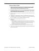
Ambient Light Sensor The new iMac G5 has an ambient light sensor. It’s located on the bottom of the display bezel, near the case screws. Look at the picture below. Next to the middle screw is a small bump protruding from the case. This is the ambient light sensor. The ambient light sensor attaches to the power supply with two plastic rivets. The ambient light sensor cable runs under the power supply and attaches to the logic board.
Removing the Back Cover Tools Required Use the screwdriver provided, or a Phillips #2 screwdriver Procedure 1. Turn your computer off by choosing Shut down from the Apple (K) menu. 2. Disconnect all cables, and unplug the power cord from your computer. Put on your ESD Wrist strap.
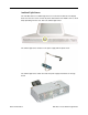
3. Place a soft, clean towel or cloth on the desk or surface. Hold the sides of the computer and slowly lay the computer face down as shown. 4. Locate the three silver case screws circled below. You may have to lift the stand to locate the middle case screw. Note: These screws are captive; they are part of the display/bezel assembly and cannot be removed. Using the tool provided, or a Phillips #2 screwdriver, loosen the three captive screws. Turn the screws to the left until they stop turning.
5. Holding the back cover by the metal stand, tilt the cover up and lift it off the computer. Set the back cover aside.
Replacing the Back Cover Tools Required Use the screwdriver provided, or a Phillips #2 screwdriver Procedure 1. Remove the replacement back cover and foot from its packaging. 2. Replace the cover so that the slots on the top edge of the back cover mate with the tabs on the display housing.
3. Lower and press the cover into place until it fits snugly on the computer. 4. Tighten the three captive case screws by turning them to the right. Don’t overtighten the screws.
5. Make sure the case is not bowing along the bottom or sides. If it is, check that the optical drive and cables are seated properly. There should be no gaps around the edges when the screws are tightened. 6. Position the computer in the upright position. Reconnect the power cord and remaining cables. Turn on the computer.
Hard Drive Tools Required • Use the screwdriver provided, or a Phillips #2 screwdriver, preferably with a magnetized tip • Flat-blade screwdriver • Screw tray or something equivalent to hold the screws Preliminary Steps Before you begin, remove the back cover.
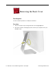
Removing the Hard Drive 1. To access the hard drive you must first remove other service modules. This procedure will show you how to remove and replace these modules. Note: As you remove each module, set it aside, along with the screws for that module. 2. Ground yourself. Touch the metal surface (as shown below) on the inside of the computer to discharge any static electricity. Warning: Always discharge static electricity before you touch any parts or install any components inside the computer.
3. Locate the fan cover near the top of the computer. 4. Using the tool provided, or a Phillips #2 screwdriver, remove the two fan cover screws. Lift the fan cover off the computer. Set the screws and fan cover aside.
5. Locate the hard drive in the top right corner. 6. Move the black video cable (located to the left of the hard drive) out of the way to access a hard drive screw.
4. Remove the three hard drive screws. Set the screws aside. 5. Carefully lift the hard drive straight up, about one inch, and disconnect the black cable from the white connector on the hard drive. Note: Leave the other end of the cable attached to the logic board.
6. Using your fingers, or a flat-blade screwdriver, disconnect the drive data cable and power cable from the hard drive. 7. Lift the hard drive up and out of the midplane assembly.Important: Return this hard drive to Apple in the packaging provided.
Replacing the Hard Drive 1. Remove the replacement hard drive from its packaging. 2. Connect the drive data cable and power cable to the hard drive. Lower the hard drive into place on the midplane. 3. Connect the black cable to the white connector on end of the hard drive.
4. Replace the three hard drive screws. 5. Tuck the black video cable into the area shown by the arrows.
6. Press the video cable into the notch on the midplane chassis. 4. Replace the two fan cover screws. The larger screw attaches on the left.
Optical Drive Tools Required • Use the screwdriver provided, or a Phillips #2 screwdriver, preferably with a magnetized tip • Screw tray or equivalent to hold the screws Preliminary Steps Before you begin, remove the back cover. Part Location Note: The education models do not have an optical drive.
Removing the Optical Drive 1. Ground yourself. Touch the metal surface (as shown below) on the inside of the computer to discharge any static electricity. Warning: Always discharge static electricity before you touch any parts or install any components inside the computer. To avoid generating static electricity, do not walk around the room until you have finished installing the part and closed the computer.
4. Using a Phillips #2 screwdriver, remove the three optical drive screws circled below. Set the screws aside. 5. Pull the optical drive tab straight up and then to the right. Set the optical drive aside.
Replacing the Optical Drive 1. Note: A microfoam insert is included with the replacement optical drive and should be installed using the instructions included below. The microfoam insert will prevent optical media from ejecting out of the system and dropping to the desktop. Only one microfoam insert should be used per system 2. Locate the enclosed piece of white microfoam and the two white posts (circled) on the bezel. 3.
4. Tuck the mircofoam into place before installing the optical drive. 5. Remove the replacement optical drive from its packaging. 6. Holding the optical drive by the back end (near the tab), insert the drive at an angle to mate the bezel with the optical drive.
7. Replace the three optical drive screws. 8. Make sure no microfoam is sticking out of the bezel. Note: Before reassembling the computer, partially insert an optical disc to make sure it inserts smoothly.
Microfoam Shim Tools Required • Use the screwdriver provided, or a Phillips #2 screwdriver, preferably with a magnetized tip • Screw tray or equivalent to hold the screws Preliminary Steps Before you begin, remove the back cover and the optical drive. Part Location Note: The education models do not have an optical drive.
Installing the Microfoam onto the Bezel 1. Steps 2-7 show photos of the microfoam on the iMac G5 20-inch computer. The installation procedure is the same for the 17-inch computer. Go on to the next step. 2. Locate the piece of microfoam and the two white posts (circled) on the bezel. 3. With the shiny side of the microfoam facing the bezel, slide the holes of the microfoam onto the two white posts on the bezel.
4. Tuck the mircofoam into place before installing the optical drive. 5. Replace the optical drive in the direction of the arrow, lining up the white posts on the bezel with the holes on the optical drive bezel.
6. Slide the optical drive into place and press down near the tab to reconnect the drive. 7. Make sure no microfoam is sticking out of the bezel. Note: Before reassembling the computer, partially insert an optical disc to make sure it inserts smoothly. 8. Replace the optical drive screws.
Fan Cover Tools Required • Use the screwdriver provided, and a Phillips #2 screwdriver, preferably with a magnetized tip • Screw tray or equivalent to hold the screws Preliminary Steps Before you begin, remove the back cover. Part Location .
Removing the Fan Cover 1. Ground yourself. Touch the metal surface (as shown below) on the inside of the computer to discharge any static electricity. Warning: Always discharge static electricity before you touch any parts or install any components inside the computer. To avoid generating static electricity, do not walk around the room until you have finished installing the part and closed the computer. 4.
Replacing the Fan Cover 1. Replace the two fan cover screws. The larger screw attaches on the left. Note: Make sure the pull tab is sticking up as shown.
Fans, Upper Tools Required • Phillips #2 screwdriver or Torx T8 (some models have torx screws on the fan) • Screw tray or equivalent to hold the screws Preliminary Steps Before you begin, remove the back cover and the fan cover.
Removing the Fans Note: Pictures from the original iMac G5 are used in this procedure. The take-apart steps are very similar. 1. Using Phillips #2, loosen the two fan screws. Note: You don’t have to remove the screws from the rubber grommets to remove the fan, just loosen the screws. 2. Disconnect the fan cable from the connector on the logic board. Pull on the black connector, not on the cable. Route the fan cable under the black cable (as shown).
3. Lift the fan out of the computer. 4. If your are replacing the fan, remove the screws from the fan grommets. Using a screwdriver, push the fan screws out of the grommets and set them aside. Use these screws on the replacement fan. 5. Go on to the next step to remove the second fan.
6. Move the video cable to the left to access the fan screw near the top of the computer 7. Using a Phillips #2, loosen the two fan screws.
8. Lift the fan out of the computer and disconnect the fan cable from the connector on the logic board. Pull on the black connector, not on the cable. 9. If you are replacing the fan, remove the screws from the fan grommets. Using a screwdriver, push the fan screws out of the grommets and set them aside.
Replacing the Fans 1. Route the fan cable under the black hard drive cable. Connect the fan cable to the connector on the logic board. Note: The fan cables are keyed. 2. Place the two screws into the grommets on the replacement fan.
3. Tuck the video cable into the space between the fan and the hard drive. 4. Lower the larger fan into the chassis, lining up the screws with the screw holes. Caution: Move the fan cable (from the smaller fan) out from under the larger fan as you lower the fan into the chassis. Tighten the two fan screws.
5. Route the fan cable under the black cable. Connect the fan cable to the logic board. 6. Replace the two fan cover screws. The larger screw attaches on the left. Note: Make sure the pull tab at the top of the case is sticking up as shown. 7. Replace the back cover.
. Fan, Lower Tools Required The only tool required is a flat-blade screwdriver. Preliminary Steps Before you begin, remove the back cover.
Removing the Lower Fan 1. With a flat-blade screwdriver, pry the metal bracket up. 2. Pull the bracket back so the fan begins to lift up.
3. Disconnect the fan connector on the logic board. Pull on the black connector not the cable. 4. Grab the fan by the sides and wiggle the fan upward. As the fan comes up, it will bump into a tab on the front bezel. See the next step.
5. Push the fan into the computer and at the same time, tilt the fan so that it clears the tab on the bezel. 6. Pull the fan cable through the metal bracket (1) as you pull the fan forward (2).
Installing the Lower Fan 1. Push the lower fan into the computer, aligning the fan with the metal bracket. Notice the location of the two gray bumps on the right side of the fan. These plastic bumps should be in this position for this step. Pull the fan cable through the metal bracket. 2. The edge of the fan (circled) has to clear the speaker. Push the fan into the computer until the edge of the fan clears the speaker.
3. As you push the fan, make sure it clears the white tab on the display bezel. Important: Notice the position of the gray bumps on the side of the fan. This is the correct position for this step. 4. Lower the fan into the chassis. Pull the metal locking clip down onto the fan making sure it secures the fan. 5.
Inverter Tools Required • Phillips #2 screwdriver, preferably with a magnetized tip • Screw tray or something equivalent to hold the screws Preliminary Steps Before you begin, remove the back cover.
Removing the Inverter 1. To access the inverter assembly other service modules have to be removed. This procedure will show you how to remove and replace each module. As you remove each module, set it aside, along with the screws for that module. 2. Important: Ground yourself. Touch the metal surface (as shown below) on the inside of the computer to discharge any static electricity. Warning: Always discharge static electricity before you touch any parts or install any components inside the computer.
4. Using a Phillips #2 screwdriver, remove the three optical drive screws circled below. Set the screws aside. 5. Pull the optical drive tab straight up and then to the right. Set the optical drive aside.
6. Locate the inverter-to-display panel cable connector. 7. Release the cable from the clip. Disconnect the cable.
4. Using a Phillips #2 screwdriver, remove the brass colored inverter screw.
5. Lift the inverter straight up to disconnect the inverter board. 6. Disconnect the white connector (circled below) by pulling it straight up. Lift the inverter out of the computer.
7. If you are installing a new inverter continue with the procedure. Turn over the inverter as shown. Using your fingers or a flat-blade screwdriver, carefully remove the gray plastic inverter cover by gently prying the tabs (circled below) away from the board. Set the plastic cover aside. 8. This cover will be attached to the replacement inverter board.
9. Return the inverter board to Apple in the packaging provided.
Replacing the Inverter 1. Remove the replacement inverter from its packaging. 2. Locate the gray plastic cover you set aside.
3. Install the plastic cover on the replacement inverter board. Gently squeeze the board near each tab (circled) until all five tabs snap onto the board. 4. Connect the white connector on the inverter board to the panel. The connector is keyed, which means it can connect only one way. Route this cable around the silver post (to the right of the cable).
5. As you lower the inverter into place, connect the pins on the inverter to the black connector on the board. Use the tall silver pins as guides to align the inverter. Important: Make sure the connector mates with the pins. Double check that it’s connected. 6. Replace the inverter screw.
4. Reconnect the inverter-to-display panel cable. Important: The connector is keyed (it fits together only one way) 5. Secure the white connector under the metal tab and tuck the lower end of the cable under the logic board.
6. Replace the optical drive. 7. Replace the optical drive screws. 8. Replace the back cover.
Memory (DIMMs) Tools Required Use the screwdriver provided, or a Phillips #2 screwdriver to open the back co Preliminary Steps Before you begin, remove the back cover.
Removing the Memory 1. Rotate the computer to the right so the memory is in the position shown below. 2. To release the memory from its slot, push down on the two side latches. Then pull the memory module out of the slot. Repeat this step if you have a second memory module. Important: Return the memory to Apple in the packaging provided.
Replacing the Memory 1. Remove the replacement memory module from its packaging. 2. Replace the memory module(s) by lining up the notch on the module with the notch on the slot. 3. Press firmly on the memory module until it clicks into place. Use your thumb and index finger to push the module into the slot.
Power Supply Tools Required • Use a Phillips #2 screwdriver • Flat-blade screwdriver Preliminary Steps Before you begin, remove the back cover.
Removing the Power Supply 1. Loosen the two captive screws (circled below). The screws are captive; they cannot be removed. 2. Loosen the middle captive screw (circled) until it’s flush with the top of the power supply. This screw attaches to the display bezel; make sure to loosen it all the way.
3. Disconnect the ambient light sensor from the logic board. 4. Turn the middle case screw clockwise about five revolutions. This releases the back cover clamp screw.
5. Disconnect the power supply connector with a flat-blade screwdriver. Loosen the connector enough so that you can remove it with your fingers. 6. Pull the power supply cable out of the connector by rocking it back and forth with your hands and pulling it toward the power supply.
7. Tilt the power supply toward you until it clears the edge of the logic board. Lift it out of the display bezel. 8. Return the power supply with the ambient light sensor to Apple in the packaging provided.
Replacing Power Supply 1. Remove the replacement power supply from its packaging. 2. The replacement power supply has an ambient light sensor attached with two plastic rivets. Route the ambient light sensor under the power supply. 3. Locate the notched-out area (circled) on the logic board. As you lower the power supply into the chassis, make sure the ambient light sensor cable lines up with notch. Note: With the cable positioned correctly, the power supply will be easier to remove.
4. Before installing the power supply, push the center screw up with a flat-blade screwdriver. Note: It will be easier to install the power supply with the screw pushed up and out of the way. 5. Tilting the power supply, line up the ambient light sensor with the opening on the display bezel. Lower the power supply into place.
6. Once the power supply is installed, check that the ambient light sensor cable is positioned in the notched-out area on the board. 7. Connect the black power supply cable and the ambient light sensor.
8. Tighten the two outer captive screws. 9. Tighten the last captive screw (circled) that attaches to the display bezel.
10. Turn the middle case screw to the left about five revolutions. This step prepares the back cover for installation. 11. Replace the back cover.
AirPort/Bluetooth Card Tools Required • T-6 screwdriver Preliminary Steps Before you begin, remove the back cover.
Removing the AirPort and Bluetooth Combo Card 1. Remove the two T-6 screws from the card. 2. Lift the card off the logic board connector. Gently disconnect the antennas from the card.
Replacing the AirPort and Bluetooth Combo Card 1. Replace the two T-6 screws. 2. Gently attach the antennas to the card. Attach the card to the connector on the logic board.
Modem Board Tools Required • T-6 screwdriver Preliminary Steps Before you begin, remove the back cover.
Removing the Modem Board 1. Remove the two T-6 screws from the card. 2. Disconnect the modem cable from the modem board.
Removing the Modem Board 1. Connect the modem cable to the board. 2. Press the board onto the connector. Replace the two T-6 screws on the board. 3. Replace the back cover.
Battery Tools Required • Flat-blade screwdriver or the nylon probe tool Preliminary Steps Before you begin, remove the back cover.
Removing the Battery 1. WIth a flat-blade screwdriver, plastic tool, thumb, or finger, push the battery in the direction of the arrow to free the battery from the metal clip.
Replacing the Battery 1. Holding the battery positive side up, push the battery (in the direction of the arrow) under the metal clip. The battery should slip into place under the clip. 2. Replace the back cover.
Midplane Tools Required • Phillips #1 and #2 screwdriver • Flat-blade screwdriver • Screw tray or equivalent to hold the screws Preliminary Steps • • • • • Before you begin, remove the following: Back cover Optical drive Inverter Fan cover Part Location Note: The midplane is no longer offered as a service module. Order the components on the midplane individually.
Removing the Midplane Assembly 1. Locate the black video cable next to the fans. Using a Phillips #1 screw. Remove the two screws and set them aside. Pull up on the black tab to disconnect the cable. Flip the cable back, so it is out of the way. 4. Using a Phillips #2 screwdriver, remove six screws. Three short screws are located in the channel along the top of the case and the longer screws attach to the chassis.
5. Loosen the middle power supply screw (a captive screwiest screw attaches the power supply to the display bezel; make sure to loosen the screw all the way. 6. Locate the pull tab at the top of the computer. Lift the midplane assembly by the tab and then grab the midplane by its the sides. As you pull in the direction of the arrow, push the cable (in the top left corner) down through the opening in the midplane.
Replacing the Midplane 1. Position the display/bezel assembly with the display face down on a clean soft cloth. 2. Make sure that the TMDS cable is tucked into the groove on the bezel as shown.
3. Lower the midplane into the display/bezel assembly housing. Pull the inverter cable through the opening in the chassis. 4. Line up the jackscrews on the right and left sides of the midplane with the holes in the display/bezel assembly.
5. Tighten the middle power supply screw (a captive screwiest screw attaches the power supply to the display bezel; make sure to tighten the screw all the way. 6. Make sure the ambient light sensor on the power supply is seated into the hole on the display bezel. You should be able to feel a bump (circled) when you run your finger across the bottom of the display bezel. If it’s not in position, reseat the midplane and check again.
7. Reconnect the video cable and replace the two video cable screws. Tuck the video cable into the area next to the fans. 8. Press the top end of the video cable into the notch on the midplane chassis.
4. Replace the six case screws. (The shorter screws attach along the top.) 5. Replace the inverter board 6. Replace the optical drive. 7. Replace the fan cover. 8. Replace the back cover.
Logic Board Tools Required • • • • • Phillips #2 screwdriver Torx T10 flat-blade Torx T6 Flat-blade screwdriver Screw tray or equivalent to hold the screws Preliminary Steps Before you begin, remove the following: • Back cover • Optical drive • Fan cover • Inverter • AirPort/Bluetooth card and disconnect the antennas • Modem card • Memory Part Location Logic Board iMac G5, 17-inch, Ambient Light Sensor
Removing the Logic Board Note: Some of these photos are taken from the original iMac G5 logic board take apart since the procedure is very similar. 1. At the top of the logic board, near the fan, disconnect the two fan cables and the two hard drive connectors. 2. Remove the two video cable screws and disconnect the video cable.
3. Disconnect the hard drive thermal sensor (near the memory slots) from the logic board. Leave the other end of the thermal sensor attached to the hard drive. 4. Using a T-8 screwdriver, disconnect the two fan duct screws and lift the duct off the logic board. Note: These two screws are longer than the other silver screws securing the logic board to the midplane chassis.
5. Disconnect the lower fan cable. 6. Disconnect the two connectors (microphone and speakers). Note: Pull on the connector, not the cables.
7. Disconnect the power supply cable and the ambient light sensor. 8. Using a T-10 screwdriver, remove six silver logic board screws and with a Phillips #2 screwdriver, remove the three brass screws on the logic board. Note: The numbers are for replacement order, disregard for take-apart. 9. Carefully lift the logic board out of the midplane chassis.
10. Look on the back side of the logic board for the light pipe. Remove the light pipe and place it on the replacement logic board. 11. If you don’t see the light pipe on the back of the logic board, it may be stuck in the chassis (shown below). Use a needlenose pliers to remove the light pipe. 12. Return the logic board to Apple in the packaging provided.
Replacing the Logic Board 1. Locate the cleaning wipe and syringe in the replacement logic board box. 2. Clean the copper heatpad (circled). Use the alcohol wipe to clean the copper heatpad.
3. Whenever you remove the logic board clean the U3 chip (circled) and reapply thermal grease. 4. Add 1 1/2 to 2 syringes of thermal grease to the U3 chip to ensure sufficient cooling. Spread the paste evenly across the surface of the chip.
5. Locate the light pipe gasket on the replacement board. Peel the adhesive backing off of the gasket. 6. Position the light pipe over the logic board so that the pin on the light pipe aligns with the hole in the logic board. Press the light pipe onto the gasket.
7. Before placing the logic board into the midplane chassis, move or tape the cables (shown below) out of the way. 8. Lower the logic board into the chassis. Caution: Do not twist, bend or flex the board as you lower it into the chassis. Flexing the board may jeopardize the thermal interface between the heartsink and the processor. Make sure the light pipe seats properly into the bottom left corner and that the cables are not caught under the board.
9. Connect the microphone and speaker cables to the logic board. 10. Using a T-10 screwdriver, replace the six silver torx logic board screws. Use a Phillips #2 to replace the three brass screws. Note: Make sure the hard drive cables are not obstructing the screw hole at the top of the logic board.
11. Connect the power supply cable and the ambient light sensor. 12. Connect the lower fan cable.
13. Connect the hard drive thermal sensor (near the memory slots) to the logic board. 14. Using a T-8 screwdriver, connect the two fan duct screws. Note: These two screws are longer than the other silver screws securing the logic board to the midplane chassis.
15. Connect the video cable to the logic board and replace the two screws. 16. Reconnect the hard drive and fan cables to the logic board. 17. Replace the memory. 18. Replace the inverter. 19. Replace the optical drive. 20. Replace the AirPort and Bluetooth card and connect the antennas. 21. Replace the modem.
22. Replace the fan cover. 23. Replace the back cover.
Antenna Cable, Right Tools Required • Nylon probe tool • Flat-blade jeweler’s screwdriver Preliminary Steps Before you begin, remove the following: • Back cover • Optical drive • AirPort and Bluetooth combo card Note: The antenna cables are identified left and right from a frontal orientation, as if you were looking at the screen.
Removing the Right Antenna Cable 1. Disconnect the antenna cable from the AirPort/Bluetooth board. 2. Release the right antenna from the metal tabs on the chassis. Use a nylon probe tool to pry up the antenna holder from its adhesive on the chassis.
Replacing the Right Antenna Cable 1. Route the exposed part of the antenna (top left side of the chassis) into the cut out on the chassis. If you are replacing the right antenna cable with a new one, rub away any remaining adhesive on the top of the midplane chassis. Peel off the backing on the replacement antenna cable, and press the antenna holder onto the chassis. Line up the two bumps on the antenna holder with the indents on the chassis. 2. Route the antenna cable under the metal tabs on the chassis.
3. Connect the AirPort and Bluetooth antennas to the AirPort/Bluetooth board. 4. Replace the AirPort/Bluetooth board. 5. Replace the optical drive. 6. Replace the back cover.
Antenna Cable, Left Tools Required • Nylon probe tool • Flat-blade jeweler’s screwdriver Preliminary Steps Before you begin, remove the following: • Back cover • Optical drive • AirPort and Bluetooth combo card • Fan cover • Upper fans Note: The antenna cables are identified left and right from a frontal orientation, as if you were looking at the screen.
Removing the Left Antenna Cable 1. Disconnect the antenna cable from the AirPort/Bluetooth board. 2. Use a jeweler’s screwdriver or a nylon probe tool to pry up the antenna holder from its adhesive on the chassis.
3. Gently free the antenna from the metal tab on the chassis and pull the antenna out from under the fan duct.
Replacing the Left Antenna Cable 1. Route the exposed part of the antenna (right side of the chassis) into the cut out (circled) on the chassis. If you are replacing the left antenna cable with a new one, rub away any remaining adhesive on the top of the midplane chassis. Peel off the backing on the replacement antenna cable, and press the antenna holder onto the chassis. Line up the two bumps on the antenna holder with the indents on the chassis.
2. Route the antenna cable under the fan duct and secure the antenna under the metal tab on the chassis. 3. Replace the upper fans. 4. Connect the AirPort and Bluetooth antennas to the AirPort/Bluetooth board. 5. Replace the AirPort/Bluetooth board. 6. Replace the optical drive. 7. Replace the fan cover. 8. Replace the back cover.
Light Pipe with Gasket Tools Required No tools are required for this procedure.
Removing the Light Pipe with Gasket Note: These instructions are from the original iMac G5 (17-inch) model. The model may look slightly different from iMac G5, 17-inch, Ambient Light Sensor model; however, the following procedure applies to both models. 1. On the underside of the midplane chassis, locate the light pipe. 2. Grasping the outer ring of the light pipe, pull it straight off the connector.
Replacing the Light Pipe with Gasket 1. Peel the adhesive backing off of the narrower end of the light pipe. 2. Note the small plastic pin on the outer ring of the light pipe. Position the light pipe over the logic board so that the pin aligns with the hole in the logic board.
3. Press the light pipe with gasket into place. 4. Replace the midplane. 5. Replace the back cover.
Microphone Cable Tools Required • Needlenose pliers • Torx T10 screwdriver Preliminary Steps Before you begin, remove the following: • Back cover • Midplane • Light pipe Part Location Microphone Cable iMac G5, 17-inch, Ambient Light Sensor
Removing the Microphone Cable 1. From the top of the logic board at the bottom of the port bank, use a needlenose pliers to disconnect the 3-pin microphone cable (left) and the speaker cable (right). 2. Turn over the midplane. Locate the microphone.
3. Remove the speaker screw (Torx T8) to access the microphone. 4. Pull the speaker forward a bit to access the microphone. Pull the microphone cable through the midplane chassis.
5. Note the routing of the microphone cable. Peel up the speaker tape, and lift up the microphone cable from the speaker channel. Slide the microphone off the speaker.
Replacing the Microphone Cable 1. Secure the microphone cable to the speaker, and apply new tape. Route the microphone cable connector through the chassis opening. 2. Slide the speaker back onto the chassis standoff. Note: A strip of new tape comes with both a replacement microphone cable and a replacement speaker set.
3. Replace the speaker screw. 4. Turn over the midplane. Connect the microphone and speaker to the logic board. 5. Replace the midplane. 6. Replace the back cover.
Speaker Set Tools Required • • • • Needlenose pliers Torx T10 screwdriver Flat-blade screwdriver Screw tray or something equivalent to hold the screws Preliminary Steps Before you begin, remove the following: • Back cover • Midplane Part Location Speaker Set iMac G5, 17-inch, Ambient Light Sensor
Removing the Speaker Set 1. Locate the two speakers on the midplane chassis. 2. From the top of the logic board at the bottom of the port bank, use a needlenose pliers to disconnect the two cable connectors: microphone and speaker. 3. Turn over the midplane. Peel back the tape securing the speaker cable to the midplane chassis.
4. Remove the speaker screw (T-10). 5. Without straining the speaker cable, use a flat-blade screwdriver to carefully open the cable guides on the underside of the midplane chassis.
6. Remove the two screws at the other speaker. 7. Slide the speaker off of the chassis standoff.
8. Repeat removal on the other speaker.
9. Replacement Note: If you are replacing the speaker set, remove the microphone cable from the speaker and transfer it to the new speaker set.
Replacing the Speaker Set 1. Note: The speaker set includes the two speakers, speaker housing, and attached cable and connector. 2. Secure the microphone cable to the speaker, and apply new tape. Note: A strip of new tape comes with both a replacement speaker set and a replacement microphone cable.
3. Replace the speaker closest to the lower fan. 4. Route the speaker cable into the cable guides. Then route the fan cable on top of it. 5. Gently press on the cable guides to ensure that the cables cannot become loose.
6. Install the remaining speaker to the chassis. 7. Replace the single screw and secure the speaker cable to the chassis with the clear tape.
8. Route the two cable connectors up through the chassis opening: 9. Connect the two connectors. 10. Replace the midplane. 11. Replace the back cover.
Lower Fan Tools Required • Flat-blade screwdriver Preliminary Steps Before you begin, remove the back cover.
Removing the Lower Fan 1. Locate the metal locking clip on the top of the fan housing. Use a flat-blade screwdriver to raise up the clip approximately 1/4 inch. 2. Push the metal locking clip all the way back until the fan begins to lift out of the computer.
3. Disconnect the fan connector on the logic board. Pull on the black connector not on the cable. 4. Grab the fan by the sides and wiggle the fan upward. As the fan comes up, the fan will bump into a tab on the front bezel. See the next step.
5. Push the fan into the computer and at the same time, tilt the fan so that it clears the tab on the bezel 6. Pull the fan cable through the metal bracket(1) as you pull the fan forward (2).
Replacing the Lower Fan 1. Push the lower fan (#1) into the chassis, aligning the fan with the metal bracket. Notice the location of the two gray bumps on the right side of the fan. These plastic bumps should be in this position for this step. Pull the fan cable (#2) through the metal bracket. 2. The edge of the fan (circled) has to clear the speaker. Push the fan into the computer until the edge of the fan clears the speaker.
3. As you push the fan, make sure it clears the white tab on the display bezel. Important: Notice the position of the gray bumps on the side of the fan. This is the correct position forsooth step. 4. Lower the fan into the display bezel. Pull the metal locking clip down onto the fan. Connect the fan cable to the logic board. 5. Replace the back cover.
LCD Panel Tools Required • Torx T10 screwdriver, preferably with a magnetized tip • Clean, soft, lint-free towel or blanket • Screw tray or something equivalent to hold the screws Preliminary Steps Before you begin, remove the following: • Back cover • Midplane Part Location LCD Panel iMac G5, 17-inch, Ambient Light Sensor
Removing the LCD Panel 1. Place the display bezel/LCD panel assembly face-down on a clean, soft, lint-free folded towel or blanket. 2. Remove the four self-tapping screws at the LCD panel brackets.
3. Touching only the top and bottom edges of the LCD panel, raise it up out of the display bezel.
Replacing the LCD Panel 1. Check the routing of the LCD panel cables. Note: The replacement LCD panel includes the brackets, cables, tape, and gaskets, as shown.
2. Make sure the cables cannot be pinched when setting the LCD panel in the display bezel. 3. Place the LCD panel into the display bezel so that all four screw holes on the brackets align with the screw holes on the bezel. 4. Replace the four screws.
5. Turn over the display bezel/LCD panel assembly, and check that there are no uneven gaps between the bezel and the display. If there are noticeable gaps, loosen the screws, reseat the panel, and retighten the screws. 6. Replace the midplane. 7. Replace the back cover.
Display Bezel Tools Required • Clean, soft, lint-free towel or blanket Preliminary Steps Before you begin, remove the following: • Back cover • Midplane • LCD panel Part Location Display Bezel iMac G5, 17-inch, Ambient Light Sensor
Removing the Display Bezel With all preliminary steps performed, the display bezel is the part that remains. Note: A diecut piece of microfoam is included with all replacement optical drives and display bezels. It should be installed in between the disc drive and the display bezel to prevent optical media from ejecting out of the system and dropping to the desktop. Only one piece of microfoam should be used per system. Refer to the replacement procedure for the front bezel for more information.
Replacing the Display Bezel 1. Before installing the LCD panel and reassembling the computer, make sure the display bezel is clean and free of dust and any foreign matter. 2. Replace the LCD panel. 3. Replace the midplane. 4. Locate the enclosed piece of white microfoam and the two white posts (circled) on the bezel. 5. With the shiny side of the microfoam facing the bezel, slide the holes of the microfoam onto the two white posts on the bezel.
6. Tuck the mircofoam into place before installing the optical drive. 7. Remove the replacement optical drive from its packaging. 8. Replace the optical drive in the direction of the arrow, lining up the white posts on the bezel with the holes on the optical drive bezel.
9. Make sure no microfoam is sticking out of the bezel. Note: Before reassembling the computer, partially insert an optical disc to make sure it inserts smoothly. 10. Replace the back cover.
Chassis Tools Required • Torx T10 screwdriver, preferably with a magnetized tip • Screw tray or something equivalent to hold the screws Preliminary Steps Before you begin, remove the following: • Back cover • Midplane assembly • Upper fans • Logic board • AirPort and Bluetooth antennas • Speaker set Part Location 152 - iMac G5, 17-inch, Ambient Light Sensor Take Chassis
Removing the Chassis 1. Remove the three T10 screws from the copper heatpad. Set the heatpad aside. 2. Note that the midplane chassis includes the fan duct, gaskets, and tape.
3. On the other side of the chassis, note that the midplane chassis includes the mesh tape that borders the hard drive area.
Replacing the Chassis 1. Transfer the copper heatpad to the replacement chassis. Replace the screws. Replacement Note: Before installing the logic board, refer to the Logic Board procedure to clean the copper heatpad and apply new thermal grease. 2. Replace the speaker set. 3. Replace the antennas. 4. Replace the logic board. 5. Replace the upper fans. 6. Replace the midplane assembly in the back cover.
Service Source Troubleshooting iMac G5, 17-inch (Ambient Light Sensor) © 2005 Apple Computer, Inc. All rights reserved.
General Information Serial Number Location The iMac G5 serial number is located on the bottom of the computer stand (foot). Note: If the back cover is replaced, copy the serial number from the original back cover to the blank label that comes with the replacement back cover. Attach the new label to the replacement back cover.
Diagnostic LEDs The iMac G5 has built-in diagnostic LEDs (shown below) on the main logic board that can help you to troubleshoot the computer. To access these LEDs, remove the back cover of the computer: 1. Turn your computer off (choose Shut Down from the Apple menu). If you can't shut it down that way, you can turn the computer off by pressing the power button for five seconds. 2. After the computer is off, disconnect all cables and the power cord from your computer.
3. Place a soft, clean towel or cloth on the desk or surface. Hold the sides of the computer and slowly lay it down so the screen is flat against the surface and the bottom is toward you. 4. Raise the foot and use a Phillips #2 screwdriver to loosen the three screws at the bottom of the computer by turning them to the left. These are “captive screws,” which means they're not supposed to come all the way out.
5. As you hold the metal foot, tilt the back cover up and lift it away from the computer. The back cover with the foot attached should come off easily. If it doesn't, make sure the screws are turned completely counter-clockwise, but not too far. 6. To protect the computer from electrostatic discharge, ground yourself by touching a metal surface inside the computer. Warning: Always discharge static electricity before you touch any parts or install any components inside the computer.
7. Locate the yellow arrow in the middle of the board. 8. Above this arrow, you'll see four LEDs: • LED 1 indicates that the trickle voltage from the power supply has been detected by the main logic board. This LED will remain ON whenever the iMac G5 is connected to a working AC power source. The LED will remain on even when the computer has been shut down or put to sleep. The LED will turn off only if the AC power source is disconnected or the power supply is faulty.
Internal Power Button To the left of the diagnostic LEDs is the internal power button. The internal power button gives you the ability to power on the computer with the back cover off the computer.
To power the computer on with the back cover off: 1. First remove the back cover. 2. Plug in the power cord. 3. Press the power button. The LEDs will come on indicating the computer status. 4. To shut the computer off with the back cover off, press the power button for at least five seconds. The green LEDs will go out.
SMU (System Management Unit) The iMac G5 uses an advanced system management unit (SMU) to manage the thermal and wattage conditions, while keeping the acoustic noise to a minimum. The SMU controls the fans and regulates the speeds to run each fan.
Ports The iMac G5 ports are shown below.
DDR Memory iMac G5 computers work with memory modules (DIMMs) that meet all of these criteria: PC3200, 2.5V, unbuffered, 8-byte, nonparity, 184-pin, 400Mhz DDR SDRAM. There are two RAM slots. The maximum amount of RAM you can install is 2 GB. You can use RAM module sizes of 256 MB, 512 MB and 1 GB, in either slot. DIMMs with any of the following features are not supported in the iMac G5 computer: registers or buffers, PLLs, ECC, parity, or EDO RAM.
Symptom Charts How to Use the Symptom Charts The Symptom Charts included in this chapter will help you diagnose specific symptoms related to the product. Because cures are listed on the charts in the order of most likely solution, try the cures in the order presented. Verify whether or not the product continues to exhibit the symptom. If the symptom persists, try the next cure. Note: If a cure instructs you to replace a module, reinstall the original module before you proceed to the next cure.
Power Issues No Power. The iMac G5 will not turn on. The display has no picture or color and no sounds can be heard coming from the fan or hard drive. 1. Verify power outlet is good. Plug a different device into the socket to ensure there is power, or plug the iMac G5 into another outlet. 2. Check the power cord. Use a known good power cord. 3. Check the connection of the power cord on both ends. Verify that the plug is securely plugged into both the AC outlet and back of the computer. 4.
7. Plug the power cord into the iMac G5 and into the AC outlet. Check to see if LED #1 is On or Off. • LED #1 is On: This indicates that the power supply is getting good power from the AC outlet. Go to step 8. • LED #1 is Off: This indicates that your power supply should be replaced. Order and install the power supply for your computer. 8. Turn the computer on by using the internal power button. With your finger, or with the nylon probe tool, press the small, metal button. Go on to the next step.
9. Does the computer start up normally after pressing the internal power button? - Yes: Press and hold the power button until the computer powers off. • Unplug the power cord from the iMac, and reinstall the back cover. • Return the computer to the upright position. • Plug the computer back in, and press the power button to turn on the computer. • Make sure the computer is starting up properly.
13. If the computer will ONLY start up from the internal power but will not power on from the power button on the back cover, the back cover may need to be replaced. Unplug the computer and remove the back cover. WIth the back cover removed, plug the power cord back in. Touch and hold an insulated screwdriver to the two contact points shown below: Does your computer start up when holding the screwdriver to these two contact points? Yes: This shows that the power button switch is working correctly.
Loud buzzing, ticking, or whining noise The computer may make a loud buzzing, ticking, or whining noise when it’s on. The sound may vary depending upon screen brightness or processor load. 1. Determine that this noise is related to the computer by removing and shutting down all other devices in the vicinity of the computer that could be causing a sound. 2. Determine if this is a power supply noise.
No Video The computer will turn on, but the display has no picture or color. The boot chime, the fan, and hard drive activity can be heard. 1. Check if the computer is sleeping. Press the space bar to wake the computer from sleep mode. 2. Did the computer wake from sleep? Yes: Put the computer to sleep from the Apple menu and wake the computer again to test the settings. Check Energy Saver setting to see when the computer has been designated to sleep. No: Continue to the next step. 3.
5. Remove the back cover to access the diagnostic LEDs on the main logic board. 6. With the back cover removed, locate the diagnostic LEDs 1 through 4 above the large yellow arrow on the main logic board. 7. Plug the power cord into the iMac G5 and into a known good AC outlet. LED #1 should come on if your computer has been starting up properly. If LED #1 is Off, see iMac G5: Troubleshooting: No Power for further troubleshooting information. 8. Turn the computer on by using the internal power button.
9. When the computer starts up, LED #2 will light after you hear the boot chime indicating the logic board is processing power correctly. If LED #2 does not light, reset the SMU (System Management Unit). Refer to “Resetting the SMU” mentioned earlier in this chapter. If LED #2 remains off after resetting the SMU, your logic board needs to be replaced. Order and install the logic board for your computer. 10.
No: Continue to next step. 13. Unplug the iMac G5 and remove the optical drive. Plug the iMac G5 back in and start the unit up from the internal power button. Does LED #3 light now? – Yes: This indicates the optical drive has failed. Replace the optical drive. – No: Replace the logic board. 14. WIth LED #3 on, turn the machine off by holding the internal power button until the unit powers off. Unplug the computer and reinstall the back cover. Return the computer to the upright position.
Display When displaying a single color over the screen area, the LCD panel shows one or more pixels that are not properly lit Active-matrix LCD technology uses rows and columns of addressable locations (pixels) that render text and images on screen. Each pixel location has three separate subpixels (red, green, and blue) that allow the image to be rendered in full color. Each subpixel has a corresponding transistor responsible for turning the subpixel on or off.
Hard Drive In a hard drive failure, the computer fails to boot to the desktop and may display a flashing question mark, or an alternating question mark and Mac OS (face o a folder) 1. Restart the computer with the Apple Hardware Test (AHT) disc that came with the computer. Run the Quick/Extended test. 2. Does the Apple Hardware Test test pass? Yes: Run Disk repair from the Install CD that came with the computer. No: Replace the component indicated by Apple Hardware Test, go on to the next step. 3.
Flashing question mark appears on the screen 1. Boot from the system CD that came with the computer and see if the hard drive mounts on the desktop. 2. Launch Drive Setup. Reinstall the system software drivers for the hard drive. 3. If no hard drive is found in Drive Setup, verify the hard drive cable connections. 4. Reinstall system software. Backup the data first. 5. Reinitialize the hard drive. 6. Replace the hard drive. 7. Replace the logic board. Optical Drive CDs or DVDs don't show up on my desktop.
No: The next thing to check to make sure the computer realizes the drive is there. From the Apple menu, choose About This Mac. From the window that pops up, click on More Info. An application called System Profiler should open. In System Profiler, in the column on the left, look under Hardware for a line called SATA. In the section on the right, you should see a header saying “S-ATA” and below it, two items. The first is your hard drive. The second is your optical drive.
information. • Unknown Error. If you see “Unknown Error”, without “-2147352480”, you will want to see Knowledge Base article 152224 for more information. • None of these alert messages. Is your disc drive the one inside the iMac, or is it attached to the iMac by a USB or FireWire cable? – Inside the Mac: Go on to step 3. – Attached by a cable: Go on to step 4. 3. So you can see other discs, it's just that they don't burn.
Inserting Discs Issue 1. Is there a disc already in the drive? Refer to Knowledge Base article 106752, “Macintosh: How to Eject a Disc When Other Options Do Not Work”. 2. Check System Profiler. In System Profiler, in the column on the left, look under Hardware for a line called S-ATA. In the section on the right, you should see a header saying “S-ATA” and below it, two items. The first is your hard drive. The second is your optical drive. Do you see two items here? Yes: Problem solved.
Fan Sound Loud fan noise coming from inside the computer The grill on the bottom of the iMac G5 lets a trio of fans draw cool air into the system. Advanced thermal software spins the fans fast or slow as needed, passing the heated air through a slit on the back cover. As the system usage increases, the fans will adjust their speed using advanced thermal software to meet the cooling needs of the system.
increase their speed to cool the system the sound level will increase. This is normal operation and none of your fans require replacement. Refer to the “Heatsink Cleaning Procedure” that follows to determine whether dust accumulating in the heatsink cooling fins may be causing the fans to run faster than normal. No: If the fan activity does not coincide with CPU usage, the sound you're hearing may not be fan activity. Go to the Next Step. 4.
- Plug the computer in and start it up by pressing the internal power button. - As the machine starts up, listen carefully to each of the fans, and see if you can locate one of the three fans of which the objectionable ticking, whistling, or squealing sound is coming from. Can you pinpoint the fan making the sound? Yes: If the sound is coming from one of the fans near the hard drive, you can order and install the Upper Fan kit for the computer.
Heatsink Cleaning Procedure Dust drawn in through the intake grill on the bottom of the iMac can gradually accumulate, eventually degrading the cooling performance of the heatsink by obstructing the air flow. 1. Before you begin, remove the back cover and the midplane assembly. 2. Remove the lower fan from it’s mounting bracket to expose the heatsink cooling fins. Note: The lower fan does not need to be disconnected from the logic board. 3.
4. If the dust has accumulated on the cooling fins than use compressed air from a can or an air compressor to blow the dust from the heatsink as shown below. 5. Inspect the lower fan and use the compressed air to clean it out if needed. 6. Inspect the lower grill on the iMac front bezel and clean if needed. 7. Reassemble the computer and retest.
Fans are running at a constant high speed If the fans on the system are running at a constant high speed, or ramp very quickly to high speed and do not vary this speed once reached, the fans are most likely receiving incorrect thermal input. In these cases you should use the following steps to resolve: 1. Reset the SMU (refer to “Resetting the SMU” mentioned earlier in this chapter) and then test to see if the fans still exhibit the issue. 2.
ready to go wireless now. 8. If your antennas are plugged in properly and your AirPort/Bluetooth card is recognized there are a number of other things that could cause issues with wireless networking. Refer to Knowledge Base document 106858 for more networking information. 9. Replace the AirPort/Bluetooth card. 10. Replace the antenna(s). 11. Replace the logic board.
My AirPort signal seems to be very week 1. Check your antenna. If the antenna is not plugged in all the way to the AirPort/ Bluetooth card, you may have very short AirPort range. 2. Remove the back cover. Reconnect the antenna cables to the card. Press the antenna connector firmly, to make sure it's fully connected to the card. Replace the cover and reconnect the power cord. 3. Try connecting to your wireless access point now.
Speakers I don’t hear sound from the speakers. 1. Press the F5 button on your keyboard. It has a sound icon on it. Do you hear sound now? Yes: It looks like your volume was muted. When this happens again, just press the F4 and F5 keys to regulate your volume. No: Are there any external microphones, speakers or headphones plugged into the iMac? If yes, go on to step 2. If no, go on to step 3. 2. Disconnect your external microphones, speakers, or headphones.
I hear sound out of only one speaker. 1. Are there any external microphones, speakers or headphones plugged into the iMac? Yes: Disconnect any external microphones, speakers, or headphones. Do you hear audio from both of the built in speakers on your iMac? – Yes: Good. It looks like the built-in speakers are working properly. This may be an issue with the microphone, speakers or headphones that were plugged into your iMac. Please work with the manufacturer to troubleshoot this issue. – No: Go to step 2.
if they have any suggestions or assistance. 3. Try a known good USB mouse. 4. Replace the mouse. 5. Replace the logic board. The mouse is slow to respond. 1. Try putting the mouse on a different surface - an opaque surface with no patterns is best. 2. Adjust the settings on the mouse. – Choose Apple menu > System Preferences and click Keyboard & Mouse. – Click Mouse. – Drag the Tracking Speed slider to select how fast the pointer moves.
Yes: Replace the keyboard. No: Replace the logic board. Certain keys don't work. 1. Unplug all devices from your computer, including your mouse and keyboard as well as printer, scanner, external hard drives, and hubs. (Warning: Some devices may require you to perform steps before it is safe to unplug them, e.g, external storage devices.) Be sure to unplug your hub, if you have one. 2. Plug your keyboard into the back of your computer firmly and securely.
When I type, strange characters appear on the screen. 1. Depending on your iMac's settings, a simple keystroke can change your keyboard from English to Japanese. This can result in some pretty funny characters showing up when you type. To switch to the US keyboard, 2. Open System Preferences. 3. Click on the International icon. 4. Click on the Input Menu near the top of the screen. 5. Scroll down the list and uncheck any non-US keyboard layouts. 6. Close the System Preferences. Try typing a few characters.
Error Beep(s) Computer beeps at startup. 1. Check that the memory DIMMs are iMac G5 compliant. iMac G5 computers work with memory modules (DIMMs) that meet all of these criteria: PC3200, 2.5V, unbuffered, 8byte, nonparity, 184-pin, 400Mhz DDR SDRAM. There are two RAM slots. The maximum amount of RAM you can install is 2 GB. You can use RAM module sizes of 256 MB, 512 MB and 1 GB, in either slot.
Error Beep(s) Symptom Charts iMac G5, 17-inch (Ambient Light Sensor) Trouble-
Service Source Views iMac G5, 17-inch (Ambient Light Sensor) © 2005 Apple Computer, Inc. All rights reserved.
iMac G5 17-inch (Ambient Light Sensor) Back Cover 076-1178 Microphone 076-1178 Cable, Hard Drive Sensor 922-6790 Cable, Hard Drive, Data 922-6788 Speakers 076-1177 Cable, Hard Drive, Power 922-6789 Ambient Light Sensor 922-6823 Light Pipe w/Gasket 922-6797 Cover, Inverter 922-6794 Kit, Upper Fan 076-1183 Cover, Heatsink, G5 922-6805 Inverter w/o Cover 661-3608 Duct 922-6829 Card, Modem, Soft 922-6492 AirPort Extreme/Bluetooth Board 661-3614 SDRAM 661-3616 1 GB, DDR 400 661-3615 512 MB, DDR 400 Lo
Screw Matrix and Part Numbers iMac G5, 17-inch (Ambient Light Sensor) Note: These are not to scale.
Note: These are not to scale.
Screw Locators To Access the Optical Drive 4 - iMac G5, 17-inch (Ambient Light Sensor) Screw Locators
To Access the Inverter Screw Locators iMac G5, 17-inch (Ambient Light Sensor) Views - 5
To Access the Fan Cover 6 - iMac G5, 17-inch (Ambient Light Sensor) Screw Locators
To Access the Upper Fans Screw Locators iMac G5, 17-inch (Ambient Light Sensor) Views - 7
To Access the Hard Drive 8 - iMac G5, 17-inch (Ambient Light Sensor) Screw Locators
To Access the Display/Bezel-Part 1 Screw Locators iMac G5, 17-inch (Ambient Light Sensor) Views - 9
To Access the Display/Bezel-Part 2 10 - iMac G5, 17-inch (Ambient Light Sensor) Screw Locators
To Access the Midplane Assembly-Part 1 Screw Locators iMac G5, 17-inch (Ambient Light Sensor) Views - 11
To Access the Midplane Assembly-Part 2 12 - iMac G5, 17-inch (Ambient Light Sensor) Screw Locators
To Access the Logic Board Remove all the cables, connectors, modem, memory, and AirPort Extreme/Bluetooth card To Access the LCD Panel First remove the midplane.
To Access the AirPort Extreme/Bluetooth Card To Access the Modem 14 - iMac G5, 17-inch (Ambient Light Sensor) Screw Locators
To Access the Speakers Screw Locators iMac G5, 17-inch (Ambient Light Sensor) Views - 15