Service Source iMac G5 (20-inch, iSight) 14 January 2008 © 2005 Apple Computer, Inc. All rights reserved.
iMac G5 (20-inch, iSight) Contents Take Apart General Information 6 Product View 6 What’s New 6 Tools Required 7 Orientation 7 Serial Number Location 7 Safety 8 Opening the Computer 9 Access Tool Modification 9 EMI Shielding 12 Lower EMI Shield 13 Speakers 14 Access Door 16 Front Bezel 18 Camera Board 26 Lower EMI Shield 32 IR Board 36 LCD Display Panel 41 Memory 49 Speakers 52 AirPort Extreme/Bluetooth Card 58 Optical Drive 61 Hard Drive 73 Power Supply, AC/DC 80 Logic Board 86 ii
AC Line Filter 97 Fan, Hard Drive 101 Fan, Optical Drive 105 Fan, CPU 108 Power Supply, DC/DC, Inverter 111 Ambient Light Sensor Board 114 Cable, Camera and IR 117 Wireless Antenna 120 Clutch 124 Chassis 128 Rear Housing 131 Stand 134 Troubleshooting General Information 139 Serial Number Location 139 Accessing the Diagnostic LEDs 139 Testing Under Power 145 SMU (System Management Unit) 146 Resetting the SMU (System Management Unit) Ports 147 DDR Memory 147 Symptom Charts 148 How to Use the Symp
Mouse 173 Keyboard 174 Error Beep(s) 176 USB 177 Views iMac G5 (20-inch iSight)—Upper Exploded View 179 iMac G5 (20-inch iSight)—Lower Exploded View 180 Screw Chart 181 iMac (iSight 20-inch) Screws page 1 181 iMac (iSight 20-inch) Screws page 2 182 iv
Service Source Take Apart iMac G5 (20-inch, iSight) © 2005 Apple Computer, Inc. All rights reserved.
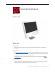
General Information Product View What’s New January 2008 • Take Apart: Corrupted graphic in the “Cable, Camera and IR” take apart section has been corrected. April 2007 • • The optical drive removal procedure has been updated. Using a screwdriver to release the optical drive tabs is causing damage to the logic board. The updated procedure shows how to remove the optical drive using a needlenose pliers.
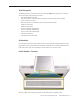
Tools Required The following tools are required to service the computer. Note that a special access card (part 922-7172) is required to open the front bezel.
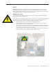
Safety Warning: When the iMac G5 (iSight) is under power, be aware that the power supply contains high voltages that pose a potential hazard to your personal safety. Never work on or near the power supply with the unit powered on, and as a further precaution always make sure the unit is unplugged when working on it with the front bezel removed. WARNING: HIGH VOLTAGE Text or photographs marked by this symbol indicate that a potential hazard to your personal safety exists from a high voltage source.
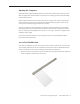
Opening the Computer Apple authorized, desktop certified technicians only should ever remove the front bezel on the iMac G5 (iSight). When the front bezel is removed, be sure to always ground yourself and follow ESD-safe repair practices Removing the front bezel requires using a special access card (part 922-7172) to release latches located inside the upper corners of the front bezel. Slightly bending the upper quarter of the access tool card will help engage the latch more securely.
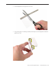
2. Cut the EMI gasket to the edge of the access card. 3. Using packing tape, or something equivalent, fold the tape over the EMI gasket to attach the gasket to the card.
4. Bend the card at a slight angle at the top to make sure the card makes contact with each latch. 5. Refer to the Front Bezel take-apart procedure for complete instructions.
EMI Shielding The iMac enclosure is wrapped in EMI shielding that is easily torn and damaged. To maintain a properly shielded unit, you must repair all accidental tears and cracks to the shielding by covering them with EMI tape. Order EMI tape, part number 922-4786 (a long, thin strip) or 9225026 (short, wide strips). Cover nicks with EMI tape. Pay particular attention to the EMI shielding inside the rear housing, shown below. The EMI shield is easily damaged when replacing modules.
Lower EMI Shield EMI tape covers the top and sides of the display panel, and the lower EMI shield covers the logic board along the bottom of the unit. The EMI tape and lower EMI shield are easily damaged when removed, and removal is necessary in order to access most components within the unit. Should the EMI tape that seals the display, or the EMI shield covering the bottom of the enclosure (see photo below) accidentally tear, use the EMI tape (922-4786 or 922-5026) to repair and completely seal the unit.
When properly repaired, all edges shown below will be wrapped by EMI tape, and the tape securely adhered to all edges. Use a “black stick” to flatten the EMI tape tightly and rub out air pockets and wrinkles. Speakers The speakers shown in this manual are black, however the final production units all have white speakers, as shown in the GSX database.
iMac G5 (20-inch iSight) Take Apart — General Information 15
Access Door Tools • • • Phillips #2 screwdriver ESD-safe workstation and mat Soft , clean towel or cloth Preliminary Steps Before you begin, lay the computer down so the panel is face down and the bottom is facing you.
Removing the Access Door 1. Raise the stand and use a Phillips #2 screwdriver, to loosen the two captive access door screws. Warning: The ambient light sensor is located between the two screws, as shown in the graphic. Don’t mistake the ambient light sensor for a screw. Sticking a screw driver or other sharp object in the ambient light sensor could damage the computer. 2. Remove the access door. Replacing the Access Door 1. Replace the access door using it to push the rings into the memory compartment.
Front Bezel Tools • • • Torx T8 screwdriver Access card tool 922-7172 ESD mat, soft , clean towel or cloth Preliminary Steps Before you begin, remove the access door.
Removing the Front Bezel 1. Position unit on rear cover (back). 2. Tilt up the front bezel and remove three screws along the bottom. Warning: The ambient light sensor is located next to the center screw. Don’t mistake the ambient light sensor for a screw. Sticking a screwdriver or other sharp object in the ambient light sensor could damage the computer. 3. Slightly bending the upper quarter of the access tool card will help engage the latch more securely.
4. This picture shows how the access tool works. Pushing the tool up the vent on the rear cover releases the latches on the inside of the front bezel. Refer to the next step for the procedure. 5. Start on the left side (looking from the back of the unit). As you insert the card to disengage the latch, squeeze the top of the bezel, that will help take pressure off of the latch and enable it to open easier. As the bezel releases, pull the bezel away from the rear housing.
6. Repeat step 5 to release the locking latch in the right corner. Again, pull the bezel away as the card releases the latch. 7. If the bezel won’t release, pull the bottom of the bezel out a bit and insert the access card again.
8. Repeat step 7 for the left side. 9. Once the access card has been removed, it is safe to open the bezel. Position the unit on an ESD mat, with the bottom facing toward you. Lift up the top of the bezel and pull it up and slightly toward you. Caution: Make sure the memory eject rings are not protruding from the access door when you lift the bezel or you could bend or damage the eject rings.
10. Swing the bezel up so you can disconnect two cables on the camera board at the top of the bezel. 11. Disconnect the camera and microphone cables from the camera board. 12. Lift the front bezel off the computer. Note the microphone is part of the front bezel assembly.
Replacing the Front Bezel 1. Make sure the black EMI shielding along the top of the LCD panel is not in the way of the bezel latches when you lower the front bezel onto the computer. Use a black stick to press (re-stick) the EMI shielding onto the panel. 2. Connect the camera and microphone cables (on the camera board) to the cables sticking out of the top of the computer.
3. Tuck the cables neatly into the channel on the rear housing. 4. Continue to lower the font bezel down over the pull rings (in the memory compartment) and then press the top corners of the front bezel to connect the magnetic latches. Note: check that the latches are connected by lifting the front bezel at each corner. 5. Replace the three front bezel screws along the bottom of the computer. 6. Replace the access door; tighten the two captive screws.
Camera Board Tools • • Torx T6 screwdriver ESD mat, soft , clean towel or cloth Preliminary Steps Before you begin, remove the access door and front bezel.
Removing the Camera Board 1. The camera board and cables are visible as you lift the front bezel off the computer. 2. Disconnect the camera and microphone cables.
3. Remove the two T6 screws on the camera board. 4. Peel back the clear mylar material to free the microphone cable from the camera board.
5. Remove the camera board from the front bezel.
Replacing the Camera Board 1. Replace the camera board on the front bezel. Carefully align and insert the camera lens until it is snug in the bezel aperture 2. Replace the two screws on the camera board. Route the microphone cable under the clear mylar. 3. Connect the camera and microphone cables.
4. Tuck the camera board cables neatly into the channel on the rear housing. 5. Continue to lower the font bezel down over the pull rings (in the memory compartment) and then lower the top corners of the front bezel so they connect with the magnetic latches. Note: check that the latches are connected by lifting the front bezel at each corner. 6. Replace the three bezel screws along the bottom of the computer. 7.
Lower EMI Shield Tools The only tool required for this procedure is a black stick (or other nonconductive nylon or plastic flat-blade tool).
Removing the Lower EMI Shield 1. Carefully peel the EMI shields off the each side of the lower rear housing. Use a black stick to help peel back the shields. 2. Carefully peel the lower EMI shield off the bottom edge of the rear housing. Use a black stick to help peel back the shield.
3.
Replacing the Lower EMI Shield 1. Position the lower EMI shield over the bottom of the unit so that the holes (for the IR board and the LED) in the shield are properly aligned. 2. Press the sticky, edge of the EMI shield onto the bottom side of the display panel. The crease in the EMI shield should align with the edge of the panel. 3. Fold down the EMI shield and press it firmly over the bottom edge of the rear housing.
IR Board Tools The only tool required for this procedure is a Torx T6 screwdriver.
Removing the IR Board 1. Disconnect the IR cable from the IR board connector. 2. Using a Torx T6 screwdriver, remove the two IR board screws. Remove the IR board from its mounting bracket. 3. Using a Torx T6 screwdriver, remove the two IR board mounting screws. Remove the IR board mounting bracket from the logic board.
4. Note: If you are replacing the IR cable, you must remove the optical drive and disconnect the cable from the logic board.
Replacing the IR Board 1. Route the IR cable as shown below and make sure the cable is connected to the logic board. 2. Install the IR board mounting bracket and screws.
3. Replace the IR board onto the mounting bracket. Connect the cable and replace the two T6 screws. 4. Replace the lower EMI shield. 5. Replace the front bezel. 6. Replace the access door.
LCD Display Panel Tools • • • Torx T6 screwdriver.
Removing the Display Panel 1. Using your fingers or a black stick, carefully peel the EMI tape off the right and left sides of the lower housing. 2. Peel the bottom of the EMI shield off the frame.
3. Peel the EMI housing up as shown. 4. Using the access tool, a black stick, or your fingers, peel the black EMI tape off the right and left sides of the panel.
5. Using the access tool or black stick, peel back the black EMI tape stuck along the entire length of the top panel.
6. Using a Torx T6 screwdriver, remove the two TMDS connector screws. Pull the black tab on the connector to disconnect the TMDS cable from the logic board. 7. Using a Torx T10 screwdriver, remove the four panel mounting screws.
8. Lift the panel up just enough to see the inverter cables on the left side. 9. Disconnect the two panel-to-inverter cables on the bottom left side of the display. Replacement Note: The cable connectors are marked with dots to indicate “right-side-up”.
10. Raise the panel up the rest of the way to locate the two inverter cables on the top left side of the display. Replacement Note: The cable connectors are marked with dots to indicate “right-side up”. 11. Lift the panel off the computer. Note: If replacing the display panel, remove the lower EMI shield (if still attached), the display panel mounting brackets, and the TMDS cable from the back of the display panel before returning the module to Apple.
Replacing the Display Panel 1. Replace the TMDS cable on the rear of the display panel. 2. If removed, replace the metal panel mounting brackets to each side of the display. 3. Connect the four inverter-to-display cable connectors. Remember the connectors are keyed; dot-side-up. 4. Replace the display panel with four mounting screws. 5. Connect the TMDS cable connector on the logic board and secure it with two screws. 6.
Memory Tools • • Phillips #2 screwdriver ESD mat, soft , clean towel or cloth Preliminary Steps Before you begin, lay the computer down so the panel is face down with the bottom is facing you; and remove the access door.
Removing the Memory 1. After removing the access door, touch the metal frame around the memory compartment to discharge any static electricity from your body. Important: Always discharge static before you touch any parts such as the memory board. To avoid generating static electricity, do not walk around the room until you have finished replacing the memory. 2. Pull the two rings in the memory compartment down simultaneously.
Replacing the Memory 1. Insert the memory module into the memory compartment. The module fits in the slot only one way (see graphic below). Note: Refer to the illustrations on the bottom of the stand for additional memory installation information. 2. Replace the access door using it to push the rings into the memory compartment. 3. Use a Phillips #2 screwdriver to tighten the captive screws on the access door.
Speakers Tools • Torx T10 screwdriver Preliminary Steps Before you begin, remove the following: • Access door • Front bezel • Lower EMI shield • Display Panel Part Location Note: The speakers on all production units are white. The following photos were taken on a preproduction unit.
Removing the Speakers 1. Using a T10 torx screwdriver, remove the screws from the left and right speakers. Replacement Note: The longer of the two speaker mounting screws is used to secure the left speaker; the shorter screw secures the right speaker. 2. Using a T6 torx screwdriver, remove the screw that secures the IR board to the IR mounting bracket. Disconnect the IR cable from the IR board.
3. Remove the IR mounting bracket screws. Lift the bracket off the logic board to free the speaker cable. Replacement Note: Take note of the location and positioning of the speaker cable (top cable in this photo) for reinstallation later. 4. Lift the speakers and attached cable straight up.
5. Under the right speaker, disconnect the speaker cable from the logic board.
Replacing the Speakers 1. Connect the speaker cable to the logic board. 2. Install the speakers and route the speaker wire as shown below. 3. Secure the right speaker with the smaller of the two mounting screws. 4. Secure the left speaker with the longer of the two mounting screws. 5. Install the metal IR mounting bracket and two T6 screws.
6. Install the IR board and two T6 screws to the IR mounting bracket. 7. Replace the display panel. 8. Replace the lower EMI shield. 9. Replace the front bezel. 10. Replace the access door.
AirPort Extreme/Bluetooth Card Tools • Torx T6 screwdriver Preliminary Steps Before you begin, remove the following: • Access door • Front bezel • Lower EMI shield • Display Panel • Speakers Part Location iMac G5 (20-inch iSight) Take Apart — AirPort Extreme/Bluetooth Card 58
Removing the AirPort Extreme/Bluetooth Card 1. Using a T6 torx screwdriver, remove the two screws on the AirPort Extreme/Bluetooth card. Pull the card straight up to disconnect it from the logic board. 2. Disconnect the two antenna cables from the AirPort Extreme/Bluetooth card.
Replacing the AirPort Extreme/Bluetooth Card 1. Connect the two antenna cables to the card. 2. Press the AirPort Extreme/Bluetooth card onto the logic board connector. Make sure the card and antennas are securely connected before installing the speakers. 3. Replace the two AirPort Extreme/Bluetooth card screws. 4. Replace the speakers and speaker screws. 5. Install the metal IR mounting bracket and two T6 screws. 6. Install the IR board and two T6 screws to the IR mounting bracket. 7.
Optical Drive Tools • • • Torx T10 screwdriver Torx T6 screwdriver Needlenose pliers (with teeth) Preliminary Steps Before you begin, remove the following: • Access door • Front bezel • Lower EMI shield • Display Panel Part Location iMac G5 (20-inch iSight) Take Apart — Optical Drive 61
Removing the Optical Drive 1. Looking at the circles below, starting with the top circle, do the following: Peel back the silver EMI tape going from the chassis frame to the optical drive, remove the two T6 screws on the optical drive flex cable, disconnect the flexible cable, and disconnect the optical drive sensor cable from the logic board. Caution: Never press down on or grasp the body of the optical drive. Pressing or squeezing the body of the optical drive could damage the mechanism.
2. Note: Make sure to use a needlenose pliers with teeth to remove the optical drive. The pliers must have a textured surface to properly grasp the optical drive release tabs. 3. Locate the black tabs at each side of the plastic optical drive mounting bracket. Starting at the release tab that is furthest from the logic board, grasp the tab with needlenose pliers, and flex the tab toward the optical drive flexible cable.
Caution: Never press down on or grasp the body (silver) of the optical drive when removing or installing it. Depressing the body of the optical drive could damage the mechanism. Grasp the optical drive by its mounting bracket only. 4. Warning: iMac main logic boards returned with physical damage such as scratches, fractures, or broken or missing components caused by improper servicing may be classified as customer abuse.
5. This photo shows the optical drive out of the computer so you can visualize how the clips move. Pressing down (#1) releases the clips (#2) outward from the metal chassis. Caution: Never press down on or grasp the body of the optical drive when removing or installing it. Pressing or squeezing the body of the optical drive could damage the mechanism. 6. If replacing the optical drive, use a T6 torx screwdriver to remove two flex cable screws attaching to the optical drive.
7. If replacing the optical drive, disconnect the sensor cable from the optical sensor located on the underside of the optical drive. Transfer the sensor cable to the replacement drive. 8. Note: The optical drive sensor can be identified by the presence of resistor R1701. The hard drive also has a sensor, but it’s resistor is R1700. Note: The optical drive sensor and mounting bracket will be attached to all replacement optical drives.
Replacing the Optical Drive 1. Install the black sensor cable and the flex cable to the optical drive with two T6 screws. 2. Insert the optical drive bezel into the rear housing, lining up the bezel with the slot opening (#1) . Be sure to align the two guide holes in the front bezel with guide posts at each end of the drive access hole. Push down on the mounting brackets (#2) to lock the optical drive securely into place on the chassis.
3. Connect the optical drive sensor to the logic board, attach the flex cable and secure it with the T6 screws, and reattach the silver EMI tape. 4. Replace the display panel. 5. Replace the lower EMI shield. 6. Replace the front bezel. 7. Replace the access door.
Handling Slot-Load Optical Drives Follow the instructions in this section carefully. This procedure shows how to handle slot-load optical drives when they are outside the computer. • Observe ESD (electrostatic discharge) guidelines when handling optical drives.
• Handle the drive only by the sides and back edge. • Do not touch the front of the drive.
• Do not press on the drive or lift it by the top and bottom cover. • Do not handle the drive by the gull wing edge only.
• When storing optical drives, use approved packaging boxes. Never stack loose drives. • When returning a defective optical drive, use the original packaging and an antistatic bag. Pack only one drive per box.
Hard Drive Tools • Torx T10 screwdriver Preliminary Steps Before you begin, remove the following: • Access door • Front bezel • Lower EMI shield • Display Panel Part Location iMac G5 (20-inch iSight) Take Apart — Hard Drive 73
Removing the Hard Drive 1. Remove the two T10 screws attaching the hard drive to the DC/DC inverter board 2. Disconnect the hard drive sensor cable from the connector on the logic board. Note the location of the sensor on the side of the hard drive and the routing of the cable.
3. The hard drive sensor is different from the optical drive sensor. The hard drive sensor can be identified by resistor R1700. Replacement Note: Make sure to transfer the sensor to the replacement hard drive. Use the double-stick tape enclosed with the replacement hard drive to attach the sensor. 4. Holding the drive by the metal bracket, pull the hard drive toward the inverter and then up to release the hard drive mounting pins from the grommets on the chassis.
5. Disconnect the hard drive power and data cables. 6. If you are replacing the hard drive, remove the temperature sensor, mounting bracket, and mounting pins (circled) before returning the drive to Apple. Transfer these parts to the replacement drive.
Replacing the Hard Drive 1. Attach the hard drive sensor and sensor cable to the side of the hard drive. 2. Attach the mounting bracket and pins if they were removed. Connect the hard drive data and power cables.
3. Route the hard drive sensor cable under the metal chassis. Connect the sensor cable to the logic board. 4. Insert the hard drive pins into the grommets. Lower the drive into the rear housing.
5. Secure the two T10 screws on the hard drive mounting bracket to the DC/DC/inverter board. 6. Replace the display panel. 7. Replace the lower EMI shield. 8. Replace the front bezel. 9. Replace the access door.
Power Supply, AC/DC Tools • Torx T10 screwdriver Preliminary Steps Before you begin, remove the following: • Access door • Front bezel • Lower EMI shield • Display Panel Part Location iMac G5 (20-inch iSight) Take Apart —Power Supply, AC/DC 80
Removing the AC/DC Power Supply WARNING: The AC/DC power supply PCB remains powered up whenever the system is plugged in, whether or not the system has been turned on. Use extreme caution when troubleshooting the system with the front bezel removed. • Don’t work alone. In the event of an electrical shock it is important to have another individual present who can provide assistance. • Keep one hand in your pocket when working on any iMac G5 (iSight) system that is plugged in.
2. Lift the power supply up and remove the cable and connector from under the chassis. This cable connects to the AC filter board located under the logic board. Note the routing of the cable under the chassis. 3. Disconnect the two power supply cables; the left cable connects to the DC/DC inverter board and the right cable connects to the AC filter board.
Replacing the AC/DC Power Supply WARNING: The AC/DC power supply PCB remains powered up whenever the system is plugged in, whether or not the system has been turned on. Use extreme caution when troubleshooting the system with the front bezel removed. • Don’t work alone. In the event of an electrical shock it is important to have another individual present who can provide assistance. • Keep one hand in your pocket when working on any iMac G5 (iSight) system that is plugged in.
2. Tuck the cables under the DC/DC power supply/inverter and the metal chassis as shown. 3. Replace the power supply screws. Install the machine screw (bottom right corner) first when installing the power supply. 4. Replace the display panel. 5. Replace the lower EMI shield. 6. Replace the front bezel. 7. Replace the access door.
8. Replace the display panel. 9. Replace the lower EMI shield. 10. Replace the front bezel. 11. Replace the access door.
Logic Board Tools • Torx T10 screwdriver Preliminary Steps Before you begin, remove the following: • Access door • Front bezel • Lower EMI shield • Display Panel • Speakers Part Location iMac G5 (20-inch iSight) Take Apart —Logic Board 86
Removing the Logic Board 1. Remove the AirPort Extreme/Bluetooth card from the logic board. Disconnect the antennas 2. Disconnect the optical cable, flex cable, and peel back the silver EMI tape from the logic board frame.
3. Using a T10 torx screwdriver, remove the seven screws on the board. Remove the selftapping screws first (black and yellow thinner circles). Replacement Note: Always install the machine screws (shown with wide white circles) before installing the self-tapping screws 4. At the top of the heatsink, remove the T-7 screw from each support bracket.
5. Note: If the replacement logic board doesn’t have the support brackets (shown below) installed on the heatsink, transfer them to the replacement logic board. Remove the two T6 screws on the top of the brackets and the T7 screws from the side support bracket. 6. Disconnect nine cables from the connectors on the logic board.
7. Lift the board enough to disconnect the hard drive data cable located on the underside of the metal railing, on the left. 8. Holding the board by the sides, lift it up and toward the top of the computer. Note: Remove the memory module from the slot before returning the board to Apple.
9. When handling the logic board, hold the board as shown below. Important: Never handle or carry the board by the heatsink or metal rails.
Replacing the Logic Board 1. Position all the logic board cables out of the way (except for the hard drive cable that attaches underneath) so the logic board can be placed into the rear housing. 2. As you lower the board into the rear housing, make sure the memory pull-tabs are lowered through the access door opening and the screw holes line up with the board.. 3.
4. Connect the hard drive data cable to the underside of the board (on the left side). Note: The hard drive is removed so you can see the location of the cable and its routing. 5. Make sure the hard drive sensor and the sensor cable are attached to the side of the hard drive. Route the sensor cable under the chassis and connect it to the logic board.
6. Replace the optical drive sensor cable, flex cable and screws, and the silver EMI tape. 7. Using a T10 torx screwdriver, replace the seven screws on the board. Always install the machine screws (drawn in yellow/white circles) before installing the self-tapping screws (shown in orange).
iMac G5 (20-inch iSight) Take Apart —Logic Board 95
8. Connect the following cables to the connectors on the logic board. Connectors are shown starting in the lower left corner, proceeding clockwise Note: The hard drive sensor cable and the optical sensor cable were connected earlier in the procedure.
AC Line Filter Tools • Torx T10 screwdriver Preliminary Steps Before you begin, remove the following: • Access door • Front bezel • Lower EMI shield • IR Board • Display Panel • Speakers • Hard Drive • Power Supply, AC/DC Part Location iMac G5 (20-inch iSight) Take Apart —AC Line Filter 97
Removing the AC Line Filter 1. Using a torx T10 screwdriver, remove the three self-tapping screws from the power inlet and the machine screw from the power inlet ground cable . 2. Carefully peel up the EMI tape on the AC filter; peel off both the large and small EMI pieces of tape. Set them aside.
3. Disconnect the AC filter cable from the power supply. Notice the routing of the AC filter cable under the chassis. 4. Lift the AC filter out of the rear housing.
Replacing the AC Line Filter 1. Install the AC power filter on the rear housing screw mounts with three self tapping screws. 2. Install the power inlet ground cable to the chassis with a machine screw. 3. Route the power inlet cable beneath the chassis as shown in the photo above, and connect it to the power supply. 4. Using the EMI tape, securely tape the top and bottom edges of the AC power inlet to the rear housing. 5. Replace the AC/DC power supply. 6. Replace the hard drive. 7.
Fan, Hard Drive Tools • No tools are required to remove the hard drive fan.
Removing the Hard Drive Fan Once the logic board and speakers have been removed, the fan will already be disconnected. Lift the fan straight up and out of the rear housing.
Replacing the Hard Drive Fan 1. Lower the fan onto the white posts in the rear housing. Push it down snug onto the posts. 2. Make sure to route the hard drive data cable under the fan as shown in the photo. Connect the hard drive cable to the logic board if it was removed during the take apart.
3. Replace the logic board. 4. Replace the speakers. 5. Replace the display panel. 6. Replace the IR Board. 7. Replace the lower EMI shield. 8. Replace the front bezel. 9. Replace the memory access door.
Fan, Optical Drive Tools • No tools are required to remove the optical drive fan.
Removing the Optical Drive Fan Once the logic board and speakers have been removed, the fan will be disconnected. Lift the fan straight up and out of the rear housing.
Replacing the Optical Drive Fan 1. Lower the fan onto the white posts in the rear housing, above the port openings. Route the fan cable around the left side of the fan, through the foam gaskets. Push it down snug onto the posts. 2. Replace the logic board. 3. Replace the speakers. 4. Replace the display panel. 5. Replace the IR Board. 6. Replace the lower EMI shield. 7. Replace the front bezel. 8. Replace the memory access door.
Fan, CPU Tools • No tools are required to remove the CPU fan.
Removing the CPU Fan Once the logic board and speakers have been removed, the fan will already be disconnected. Lift the fan straight up and out of the rear housing.
Replacing the CPU Fan 1. Lower the fan onto the white standoffs in the rear housing. Push it down snug onto the posts. 2. Replace the logic board. 3. Replace the speakers. 4. Replace the display panel. 5. Replace the IR Board. 6. Replace the lower EMI shield. 7. Replace the front bezel. 8. Replace the memory access door.
Power Supply, DC/DC, Inverter Tools • Torx T10 screwdriver Preliminary Steps Before you begin, remove the following: • Access door • Front bezel • Lower EMI shield • IR Board • Display Panel • Speakers • Logic Board • Hard Drive • Power Supply, AC/DC • Hard drive fan • CPU fan Part Location iMac G5 (20-inch iSight) Take Apart —Power Supply, DC/DC, Inverter 111
Removing the DC/DC Power Supply/Inverter 1. Using a torx T10 screwdriver, remove the two power supply, DC-DC inverter screws connecting the board to the rear housing. Disconnect the two cables; one going to the ACDC power supply and the other connecting to the hard drive. 2. Remove just the circled chassis screws, one of which is the AC filter ground screw. Carefully lift the chassis frame just enough to pull the inverter cable from under the metal chassis.
Replacing the DC/DC Power Supply/Inverter 1. Route the inverter cable under the metal chassis frame. Check the routing of the cable so it doesn’t get pinched under the chassis. 2. Install the screws on the chassis frame and the AC filter ground screw. 3. Replace the CPU fan. 4. Connect the cables to the AC/DC power supply and to the hard drive. Replace the two screws connecting the DC/DC power supply/inverter to the rear housing. 5. Replace the AC/DC power supply. 6. Replace the hard drive. 7.
Ambient Light Sensor Board Tools • A black stick or equivalent tool Preliminary Steps Before you begin, remove the following: • Access door • Front bezel • Lower EMI shield • IR Board • Display Panel • Speakers • Logic Board Part Location iMac G5 (20-inch iSight) Take Apart —Ambient Light Sensor Board —114
Removing the Ambient Light Sensor Board 1. Remove the rubber bumper from between the chassis and the sensor board. 2. Using a black stick, pry the ambient light sensor off the inside of the rear housing. The sensor is stuck to the rear housing with double-stick tape. Note: never poke the ambient light or you could damage the sensor board.
Replace the Ambient Light Sensor Board 1. Press the sticky side of the ambient light sensor board to the bottom inside edge of the rear housing. 2. Install the rubber bumper between the back of the sensor board and the chassis. 3. Replace the logic board. 4. Replace the speakers. 5. Replace the display panel. 6. Replace the IR Board. 7. Replace the lower EMI shield. 8. Replace the front bezel. 9. Replace the memory access door.
Cable, Camera and IR Tools No tools are required to remove the camera cable.
Removing the Camera and IR Cable 1. Remove the two-headed end of the cable from the access hole in the upper EMI Faraday shield. 2. Remove the tape that secures the cable to the rear housing and disconnect the cable from the logic board. Remove the camera cable.
Replacing the Camera and IR Cable 1. Insert the two-headed end of the camera cable through the access hole in the upper EMI Faraday shield. 2. Route the camera cable as shown below. Tape the camera cable to the rear housing. 3. Replace the optical drive, flex drive cable and screws, and optical drive sensor cable. 4. Replace the logic board. 5. Replace the speakers. 6. Replace the display panel. 7. Replace the IR Board. 8. Replace the lower EMI shield. 9. Replace the front bezel. 10.
Wireless Antenna Tools • Black stick (or other nonconductive nylon or plastic flat-blade tool) Preliminary Steps Before you begin, remove the following: • Access door • Front bezel • Lower EMI shield • Speakers • AirPort Extreme/Bluetooth Card • IR Board • Display Panel • Optical Drive • Logic Board • Optical Drive Fan iMac G5 (20-inch iSight) Take Apart —Wireless Antenna 120
Part Location iMac G5 (20-inch iSight) Take Apart —Wireless Antenna 121
Removing the Wireless Antenna Cable 1. Carefully peel back the EMI Faraday shield and backing from the top right inside corner of the rear housing as shown below. Peel back just enough of the Faraday shield backing to access the antenna cable. 2. Using a flat-blade screwdriver, pry the antenna off the top of the rear housing. 3. Pull the antenna cables through the side access hole in the Faraday shield.
Replacing the Wireless Antenna Cable 1. Attach the antenna board to the top inside of the rear housing with double-stick tape. 2. Route the antenna cable along the top inside corner of the rear housing. Make sure the antenna cable routes around the white post in the corner. Check that the cable doesn’t protrude from the vent on the rear housing. 3. Route the antenna cable as shown above and insert the connector’s end of the cable through the access hole in the Faraday shield.
Clutch Tools • Torx T10 screwdriver Preliminary Steps Before you begin, remove the following: • Access door • Front bezel • Lower EMI shield • Speakers • AirPort Extreme/Bluetooth Card • IR Board • Display Panel • Logic Board • CPU Fan Part Location iMac G5 (20-inch iSight) Take Apart —Clutch 124
Removing the Clutch 1. Remove the EMI tape attached along the top and bottom sides of the clutch cover. After removing the tape, pull the cover straight off the clutch. 2. Peel back the EMI tape on top of the mechanism. Using a torx T10 screwdriver, remove the four clutch mounting screws.
3. Stand up the unit, to access the clutch-to-stand mounting screws. 4. Using a T10 torx screwdriver, remove the seven clutch-to-stand screws. Separate the mechanism and the stand from the rear housing.
Replacing the Clutch 1. Make sure the stand is erect and the end of the stand is inserted through the mounting hole in the rear housing. 2. Position the clutch on the stand, with the clutch springs at bottom. Install the seven long, clutch-to-stand mounting screws. 3. Adjust the clutch so that its chassis mounting holes align, and install the four screws that secure the clutch to the chassis. 4. Replace the silky EMI tape on top of the mechanism, press it into place. 5.
Chassis Tools • Torx T10 screwdriver Preliminary Steps Before you begin, remove the following: • Access door • Front bezel • Lower EMI shield • Speakers • AirPort Extreme/Bluetooth card • IR board • Display panel • Optical Drive • Logic board • CPU Fan • AC Line Filter • Hard drive • Power supply, AC/DC • Clutch • Stand iMac G5 (20-inch iSight) Take Apart —Chassis 128
Part Location Removing the Chassis Using a T10 screwdriver, remove 12 self-tapping screws from the chassis, and remove the chassis from the rear housing.
Replace the Chassis 1. Position the chassis on the rear housing as shown and install 12 self-tapping mounting screws. 2. Replace the clutch mechanism. 3. Replace the AC line filter. 4. Replace the AC/DC power supply. 5. Replace the hard drive. 6. Replace the optical drive. 7. Replace the hard drive and optical drive fans (if removed). 8. Replace the CPU fan. 9. Replace the logic board. 10. Replace the speakers. 11. Replace the display panel. 12. Replace the IR Board. 13.
Rear Housing Tools No tools are required to remove the rear housing.
Part Location Removing the Rear Housing Using a T10 torx screwdriver, remove 12 self-tapping screws from the chassis, and remove the chassis from the rear housing. Note: the EMI Faraday shield is part of the rear housing.
Replace the Rear Housing 1. Position the chassis on the rear housing as shown and install 12 self-tapping mounting screws. 2. Replace the clutch mechanism. 3. Replace the stand. 4. Replace the AC line filter. 5. Replace the AC/DC power supply. 6. Replace the hard drive. 7. Replace the optical drive. 8. Replace the hard drive and optical drive fans (if removed). 9. Replace the CPU fan. 10. Replace the logic board. 11. Replace the speakers. 12. Replace the display panel. 13.
Stand Tools • Torx T10 screwdriver Preliminary Steps Before you begin, remove the following: • Access door • Front bezel • Lower EMI shield • Speakers • AirPort Extreme/Bluetooth Card • IR Board • Display Panel • Logic Board • CPU Fan • Clutch Part Location iMac G5 (20-inch iSight) Take Apart —Stand 134
Removing the Stand 1. Stand up the unit, to access the clutch-to-stand mounting screws. 2. Using a T10 torx screwdriver, remove the seven clutch-to-stand screws. Separate the mechanism and the stand from the rear housing.
Replacing the Stand 1. Make sure the stand is erect and the end of the stand is inserted through the mounting hole in the rear housing. 2. Position the clutch on the stand, with the clutch springs at bottom. Install the seven long, clutch-to-stand mounting screws. 3. Adjust the clutch so that its chassis mounting holes align, and install the four screws that secure the clutch to the chassis. 4. Replace the silky EMI tape on top of the mechanism, press it into place. 5.
iMac G5 (20-inch iSight) Take Apart —Stand 137
Service Source Troubleshooting iMac G5 (20-inch, iSight) © 2005 Apple Computer, Inc. All rights reserved.
General Information Serial Number Location iMac G5 (iSight) serial numbers are located on the bottom of the computer stand. Accessing the Diagnostic LEDs The iMac G5 (20-inch iSight) has four built-in diagnostic LEDs on the main logic board that can help you troubleshoot the computer. Follow the steps below to access the LEDs. 1. Shut down the computer and disconnect all cables except the power cord. 2. Place a soft, clean towel or cloth on the desk or flat surface.
4. Turn over the unit and place it screen-up, with the bottom facing toward you. 5. Tilt up the front bezel and use a T8 torx screwdriver to remove the three bezel mounting screws. 6. Stand up the unit. Using the plastic access card, unhook the bezel locking mechanism in one upper corner of the front bezel, and pull the bezel slightly away from the rear housing. Note: You must Insert the access card through the vent in the rear housing as shown below, and push it up and back until the latch releases.
7. Repeat step 6 to release the locking mechanism in the opposite upper corner. 8. Lay the unit screen-up on an ESD mat, with the bottom facing toward you. Lift up the top of the bezel and pull it slightly toward you to separate it from the top of the rear housing.
9. Lift the front bezel straight up to remove it. Then swing the bezel upright onto its top edge so you can disconnect two cables that tether the bezel to the rest of the unit. Caution: Make sure the memory eject rings are not protruding from the bezel when you lift it or you could bend or damage the rings. Also, do not use excessive force when removing the front bezel or you could break the locking mechanisms.
11. To protect the computer from electrostatic discharge, ground yourself by touching the metal frame around the display panel. Caution: Always discharge static electricity before you touch any parts or install any components inside the computer. 12. Carefully peel the lower EMI shield off the bottom edge of the rear housing. Use a black stick to help peel back the shield. 13. Remove the speakers. The LEDs are under the right speaker.
14. The four labelled diagnostic LEDs shown below. • LED 1: Indicates that trickle voltage from the AC power inlet to the power supply has been detected. This LED will be ON when the computer is turned off and your power supply is working correctly. • LED 2: Indicates that the main logic board has detected proper power from the power supply when the computer is turned on. This LED will be ON when the computer is turned on and the power supply is working correctly.
Testing Under Power Using the diagnostic LEDs to check for power issues requires powering on the system with the diagnostic LEDs visible. To access the Diagnostic LEDs, follow the preceding steps under “Accessing the Diagnostics LEDs.” Never remove components not included in the “Accessing the Diagnostic LEDs” procedure when testing the system under power.
SMU (System Management Unit) The iMac G5 (iSight) uses an advanced system management unit (SMU) to manage the thermal and wattage conditions, while keeping the acoustic noise to a minimum. The SMU controls the fans and regulates the speeds to run each fan.
Ports The iMac G5 (20-inch iSight) ports are shown below. DDR Memory iMac G5 (20-inch iSight) computers work with memory modules (DIMMs) that meet all of these criteria: PC3200, 2.5V, unbuffered, 8-byte, nonparity, 184-pin, 533Mhz DDR2 SDRAM. iMac G5 (20-inch iSight) comes with 512 MB of memory soldered to the main logic board, and includes one user-configurable RAM slot. User-configurable memory can be installed by the customer by removing the memory access door on the bottom edge of the unit.
Symptom Charts How to Use the Symptom Charts The Symptom Charts included in this chapter will help you diagnose specific symptoms related to the product. Because cures are listed on the charts in the order of most likely solution, try the cures in the order presented. Verify whether or not the product continues to exhibit the symptom. If the symptom persists, try the next cure. Note: If a cure instructs you to replace a module, reinstall the original module before you proceed to the next cure.
Power Issues No Power. The iMac G5 will not turn on. The display has no picture or color and no sounds can be heard coming from the fan or hard drive. 1. Verify power outlet is good. Plug a different device into the socket to ensure there is power, or plug the iMac G5 into another outlet. 2. Check the power cord. Use a known good power cord. 3. Check the connection of the power cord on both ends. Verify that the power cord is securely plugged into both the AC outlet and the back of the computer. 4.
7. Plug the power cord into the iMac G5 and into the AC outlet. Check to see if diagnostic LED #1 is On or Off. LED #1 is On: This indicates that the AC power inlet and AC-to-DC power supply is getting good power from the AC outlet, and the DC-to-DC board is receiving 12VDC. Go to step 8. LED #1 is Off: Inspect for loose or disconnected cables. If cables are connected, your AC-toDC power supply or AC power inlet may need to be replaced.
8. Turn the computer on by pressing the power button on the rear of the case. Go to the next step. 9. Does the computer start up normally after pressing the power button? Yes: Press and hold the power button until the computer powers off. Unplug the power cord from the iMac, and replace the front bezel. Return the computer to the upright position and connect the power cord. Press the power button to turn on the computer. Make sure the computer starts up properly.
Audible buzzing, whining, or ticking noise The iMac G5 (iSight) contains several mechanical devices such as motors and fans that may make audible buzzing, ticking, or whining noises when they are operating in a normal manner. The sounds will vary depending on how the system is used. When troubleshooting abnormal noises try the following: 1. Verify that the computer is running a supported version of the Mac OS X operating system.
No Video The computer will turn on, but the display has no picture or color. The boot chime, the fan, and hard drive activity can be heard. 1. Check if the computer is sleeping. Press the space bar to wake the computer from sleep mode. 2. Did the computer wake from sleep? Yes: Put the computer to sleep from the Apple menu and wake the computer again to test the settings. Check Energy Saver setting to see when the computer has been designated to sleep. No: Continue to the next step. 3.
8. Turn on the computer by pressing the power button. 9. When the computer starts up, LED 2 will light, indicating the power supply is functioning properly. If LED 2 does not light, refer to the “No Power” troubleshooting earlier in this chapter. 10. LED 3 will light last, indicating that the logic board and LCD assembly have communicated and the LCD is ready to receive video. Does LED 3 come on? Yes: This indicates that your logic board is working correctly to produce video. Continue to step 12.
Display is tinted another color. 1. Reset the parameter RAM. Press the Command-Option-P-R keys. When you keep all the keys held down, you will hear the startup chime over and over again (about every ten seconds) until you let go. After you hear the second chime, you can let go of the keys. Does the computer display video after successfully resetting the computer’s PRAM? Yes: Problem resolved. Restart the computer from the Apple menu and make sure the computer display is no longer tinted another color.
Display When displaying a single color over the screen area, the LCD panel shows one or more pixels that are not properly lit Active-matrix LCD technology uses rows and columns of addressable locations (pixels) that render text and images on screen. Each pixel location has three separate subpixels (red, green, and blue) that allow the image to be rendered in full color. Each subpixel has a corresponding transistor responsible for turning the subpixel on or off.
Hard Drive Flashing question mark, or an alternating question mark and Mac OS (face or a folder) Note: When troubleshooting hard drive problems it is a good idea, if possible, to back up any important data. Some troubleshooting steps may require erasing the contents of the hard drive. 1. Boot from the system CD that came with the computer, and open Disk Utility. Does the hard drive show in Disk Utility? Yes: Run Repair Disk and Repair Permissions to correct any directory and permissions issues.
Optical Drive CDs or DVDs don’t show up on the Desktop. 1. Select Preferences from the Finder menu and make sure the option to show CDs, DVDs and iPods is checked: in the General window as shown below.
2. Select System Preferences from the Apple menu and open the CDs & DVDs preferences window. Make sure that audio CDs are set to launch iTunes and movie DVDs set to launch DVD Player when those media are inserted, as shown below. 3. Check that the drive can read discs normally. Insert an audio CD and check whether it shows up on your desktop or launches iTunes. Does the audio CD mount on the desktop or in iTunes? Yes: The drive seems to read CD discs okay. Go on to Step 4.
The computer won’t burn discs. 1. Check whether the drive can read CDs and DVDs normally. Perform the steps above for “CDs or DVDs don’t show up on the Desktop.” 2. Try a test burn by creating a Burn Folder, as follows. • In the Finder, choose “New Burn Folder” from the File menu. • Open the Burn Folder, drag an item inside for testing, and click “Burn” in the upper right corner of the window. • When prompted, insert a blank disc and follow the dialog instructions.
No: Replace the optical drive. Does it burn correctly now? Yes: Problem solved. No: Replace the logic board. Discs won’t insert. 1. Is there a disc already in the drive? Yes: Eject the disc before inserting another. Refer to Knowledge Base article 106752, “Macintosh: How to Eject a Disc When Other Options Do Not Work”. If none of these options will eject the disc, you may have to disassemble the drive to recover the disc.
Optical disc constantly ejects 1. Disconnect all peripheral devices, especially the mouse in cases where the disc is constantly ejecting. Retest. If the issue is resolved, reconnect peripherals one-at-a-time until faulty peripheral is identified. 2. Try cleaning the disc. If the disc is dirty or scratched, it may not mount. Is the issue resolved? Yes: Problem solved. No: Try a different disc. If the issue persists, go on to the next step. 3.
Fan Sound Loud fan noise coming from inside the computer The iMac G5 (20-inch iSight) has a trio of fans that circulate air throughout the system. It also includes temperature sensors, and advanced thermal software that spins the fans fast or slow as needed. As the system usage increases, the fans will adjust their speed using advanced thermal software to meet the cooling needs of the system.
No: If the fan activity does not coincide with CPU usage, the sound you’re hearing may not be fan activity. Go to the Next Step. 4. The normal functioning of the hard drive and optical drive will generate additional whirring and scratching noises that may be audible. We can isolate these noises by booting the computer to the iMac G5 Install Mac OS X Install Disc 1. - Place the disc in the drive, and restart your machine while holding down the “C” key as the machine starts up.
Fans are running at a constant high speed If the fans on the system are running at a constant high speed, or ramp very quickly to high speed and do not vary once this speed is reached, the fans are most likely receiving incorrect thermal input. Follow these steps: 1. Reset the SMU (refer to “Resetting the SMU” mentioned earlier in this chapter) and then test to see if the fans still exhibit the issue. 2. Boot to Apple Service Diagnostic v2.5.
AirPort/Bluetooth Not able to connect wirelessly with AirPort or Bluetooth 1. From the Apple menu, choose About this Mac. 2. Click on More Info. System Profiler should open. 3. In System Profiler, in the column on the left, look under Hardware for a line called “AirPort Card”. Select that line. 4. Does the section to the right say “No Information Found”? Yes: The computer doesn’t realize it has an AirPort/Bluetooth combo card installed. Go to step.
AirPort signal seems to be very weak 1. Check the antenna. If the antenna is not plugged in all the way to the AirPort/Bluetooth combo card, AirPort range may be very short. Remove the front bezel, lower EMI shield, right speaker, and the combo card mounting screw. Disconnect and turn over the combo card, and reconnect the antenna cables to the card. Press the antenna connector firmly to make sure it’s fully connected to the card. Replace the cover and reconnect the power cord. 2.
IR Remote Remote won’t communicate with system applications such as iTunes or iPhoto, or with the optical drive. Make sure of the following when using the Apple Remote: • You are within 30 feet of the front of the computer. • You have an unobstructed line-of-sight to the front of the computer. • You are pointing the lens end of the Apple Remote directly at the front of the computer. • The computer is powered on and awake.
IR Sensor/Receiver Supported applications do not respond to input from the remote control. 1. Perform the checks above under “IR Remote” to verify that the Apple Remote is functioning correctly, and retest. Do supported applications now respond to input from the IR remote? Yes: Problem resolved. No: Go to the next step. 2. Verify that the IR Sensor can be seen in the Apple System Profiler. Open the Apple System Profiler and click on the “USB” section.
Built-in iSight Camera The built-in camera is not recognized. 1. Boot the iMac G5 to the desktop and launch iChat AV. Note: You do not need to be connected to a network to use iChat AV to troubleshoot. Verify that the correct versions of Mac OS X and iChat AV are installed. Reinstall or update software as needed. 2. Open the iChat AV preferences and click on the ‘Video’ icon. Verify whether the camera is recognized by the iChat AV software.
iChat AV connection doctor feature to verify that there is sufficient bandwidth to have a video iChat session without a significant degradation of image quality. No: The camera may not be functioning normally. Replace the camera board in the front bezel and retest. Camera recognized but no audio 1. Open the System Preferences window and click on Sound. 2. Verify that the built in iSight camera has been selected as the device for sound input. 3.
Speakers Can’t hear sound from the speakers. 1. Disconnect any external microphones, speakers, or headphones. 2. Access System Preferences and select Sound. In the Sound pane, select Output and make sure the Internal speakers are selected as the device for sound output, the Output volume is adequate, and Mute is not selected. M. Do you have sound now? Yes: Problem resolved. No: Go to the next step. 3. Reset parameter RAM.
Mouse My mouse doesn’t work at all. 1. Try using the mouse on another surface. Non-reflective, opaque surfaces without repetitive patterns work best. The surface should be clean, but not shiny. 2. Unplug any USB devices plugged into your computer, other than the Apple Mouse and Apple Keyboard. 3. Try another known good USB mouse. 4. Replace the mouse. 5. Replace the logic board. My mouse works intermittently (the cursor freezes randomly). 1.
Keyboard None of the keys on my keyboard work. 1. Unplug all devices from your computer, including your mouse and keyboard as well as printer, scanner, external hard drives, and hubs. (Warning: Some devices may require you to perform steps before it is safe to unplug them, e.g, external storage devices.) Be sure to unplug your hub, if you have one. 2. Plug your keyboard into the back of your computer firmly and securely. Plug your mouse into the back of your computer firmly and securely.
occupied. Go on to step 4. 4. Does your mouse work now? Yes: Replace the keyboard. No: Replace the logic board. My keys are sticky or slow to respond. 1. Try a known good keyboard. 2. Open System Preferences. Click on the keyboard and mouse icon. Adjust the “key repeat speed and delay until repeat” rate. 3. Replace the keyboard. When I type, strange characters appear on the screen. 1. Depending on your iMac’s settings, a simple keystroke can change your keyboard from English to Japanese.
Error Beep(s) Computer beeps at startup. 1. Check that the memory DIMMs are iMac G5 (20-inch iSight) compliant. iMac G5 (20-inch iSight) computers work with memory modules (DIMMs) that meet all of these criteria: • • DDR2 SDRAM (Double Data Rate 2, Synchronous Dynamic Random Access Memory) • 533 MHz, PC2-4200 compliant (also referred to as DDR2 533) • 184-pin, 2.5V • unbuffered and unregistered There is one RAM slot. The maximum amount of RAM you can install is 2.5 GB.
USB A USB device doesn’t work 1. Please unplug all of your USB devices from your iMac except your Apple Keyboard and Apple mouse. 2. Now plug your device directly into the back of your iMac. Does it work as expected now? Yes: Your device works when plugged directly into the computer. This indicates a conflict with one of the other USB devices. You can test by gradually adding your devices back and seeing where the issue occurs, then contacting the manufacturer of the device(s)) for assistance.
Service Source Views iMac G5 (20-inch, iSight) © 2005 Apple Computer, Inc. All rights reserved.
iMac G5 (20-inch iSight)—Upper Exploded View Camera Board 661-3782 Camera Board/IR Cable 922-6994 Display Panel, LCD 661-3779 Bracket,LCD, Left 922-7005 Shield, EMI, Lower LCD (not shown) 922-7137 TMDS Cable 922-6986 Speakers 922-6988 Front Bezel, 20” 922-6998 Bracket, LCD, Right 922-7004 Optical Flex Cable 922-7160 Optical Drive w/Bezel 661-3873 Optical Sensor Cable 922-6995 Optical Bezel 922-6997 Optical Drive Temp Sensor 922-7168 Fan, CPU 922-6992 Fan, Hard Drive 922-6993 Cable HD, Data, Sata 922-69
iMac G5 (20-inch iSight)—Lower Exploded View AC Line Filter 922-7147 Fan, Optical Drive 922-6991 Cover, Stand Mechanism 922-7007 Power Supply AC/DC 661-3780 Antenna, Wireless 922-6987 Power Supply, DC/DC, Inverter 661-3781 Rear Housing 922-6999 Access Door, Memory 922-7009 Ambient Light Sensor 922-7161 SDRAM 661-3783 512 MB, 533 661-3784 1 GB, 533 661-3785 2 GB, 533 IR Board 922-7135 Apple Remote 661-3756 Stand 922-7003 Stand Mechanism 922-7002 (Not Shown) Chassis 922-7006 Not Shown: Modem, Exte
Screw Chart iMac (iSight 20-inch) Screws page 1 Note: Screws are not to scale.
iMac (iSight 20-inch) Screws page 2 922-7001 head T8, round Hard drive pins (2) 922-7069 T10 A/C to chassis 922-7014 T10 922-7009 C-Clip for the access door 922-7023 Access door C-Clip LCD assembly to rear cover 922-7159 T10 922-7019 T10 T8 Power supply to chassis Hard drive clip to hard drive 922-7015 922-7018 T10 T8 Left speaker, 20-inch Right speaker, 20-inch Optical bezel to optical drive 922-7011 922-7079 922-7020 T8 Front bezel to bottom frame Phillips #2 User access doo
922-7162 T6 Optical drive flex board to logic board 922-7066 T10 Power supply to rear cover iMac G5 (iSight 20-inch) Views 183